ECU AUDI A8 2000 D2 / 1.G 01V Transmission Remove And Install Workshop Manual
[x] Cancel search | Manufacturer: AUDI, Model Year: 2000, Model line: A8, Model: AUDI A8 2000 D2 / 1.GPages: 64, PDF Size: 1.44 MB
Page 4 of 64
37-74
All except 2.7 Liter 5V turbo engine:
- Remove cover above air filter housing.
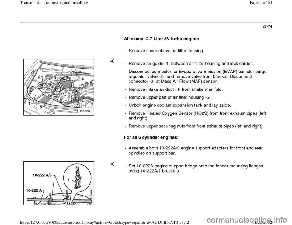
For all 6 cylinder engines: - Remove air guide -1- between air filter housing and lock carrier.
- Disconnect connector for Evaporative Emission (EVAP) canister purge
regulator valve -2-, and remove valve from bracket. Disconnect
connector -3- at Mass Air Flow (MAF) sensor.
- Remove intake air duct -4- from intake manifold.
- Remove upper part of air filter housing -5-.
- Unbolt engine coolant expansion tank and lay aside.
- Remove Heated Oxygen Sensor (HO2S) from front exhaust pipes (left
and right).
- Remove upper securing nuts from front exhaust pipes (left and right).
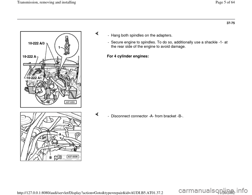
- Assemble both 10-222A/3 engine support adapters for front and rear
spindles on support bar.
- Set 10-222A engine support bridge onto the fender mounting flanges
using 10-222A/1 brackets.
Pa
ge 4 of 64 Transmission, removin
g and installin
g
11/20/2002 htt
p://127.0.0.1:8080/audi/servlet/Dis
play?action=Goto&t
yp
e=re
pair&id=AUDI.B5.AT01.37.2
Page 5 of 64
37-75
For 4 cylinder engines: - Hang both spindles on the adapters.
- Secure engine to spindles. To do so, additionally use a shackle -1- at
the rear side of the engine to avoid damage.
- Disconnect connector -A- from bracket -B-.
Pa
ge 5 of 64 Transmission, removin
g and installin
g
11/20/2002 htt
p://127.0.0.1:8080/audi/servlet/Dis
play?action=Goto&t
yp
e=re
pair&id=AUDI.B5.AT01.37.2
Page 8 of 64
37-78
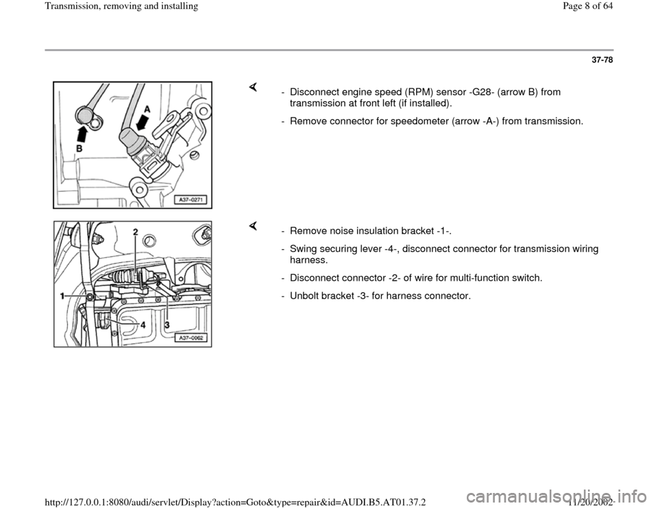
- Disconnect engine speed (RPM) sensor -G28- (arrow B) from
transmission at front left (if installed).
- Remove connector for speedometer (arrow -A-) from transmission.
- Remove noise insulation bracket -1-.
- Swing securing lever -4-, disconnect connector for transmission wiring
harness.
- Disconnect connector -2- of wire for multi-function switch.
- Unbolt bracket -3- for harness connector.
Pa
ge 8 of 64 Transmission, removin
g and installin
g
11/20/2002 htt
p://127.0.0.1:8080/audi/servlet/Dis
play?action=Goto&t
yp
e=re
pair&id=AUDI.B5.AT01.37.2
Page 13 of 64
37-83
Continuation for all vehicles
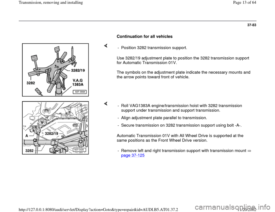
Use 3282/19 adjustment plate to position the 3282 transmission support
for Automatic Transmission 01V.
The symbols on the adjustment plate indicate the necessary mounts and
the arrow points toward front of vehicle. - Position 3282 transmission support.
Automatic Transmission 01V with All Wheel Drive is supported at the
same positions as the Front Wheel Drive version. - Roll VAG1383A engine/transmission hoist with 3282 transmission
support under transmission and support transmission.
- Align adjustment plate parallel to transmission.
- Secure transmission on 3282 transmission support using bolt -A-.
- Remove left and right transmission support with transmission mount
page 37
-125
Pa
ge 13 of 64 Transmission, removin
g and installin
g
11/20/2002 htt
p://127.0.0.1:8080/audi/servlet/Dis
play?action=Goto&t
yp
e=re
pair&id=AUDI.B5.AT01.37.2
Page 15 of 64
37-85
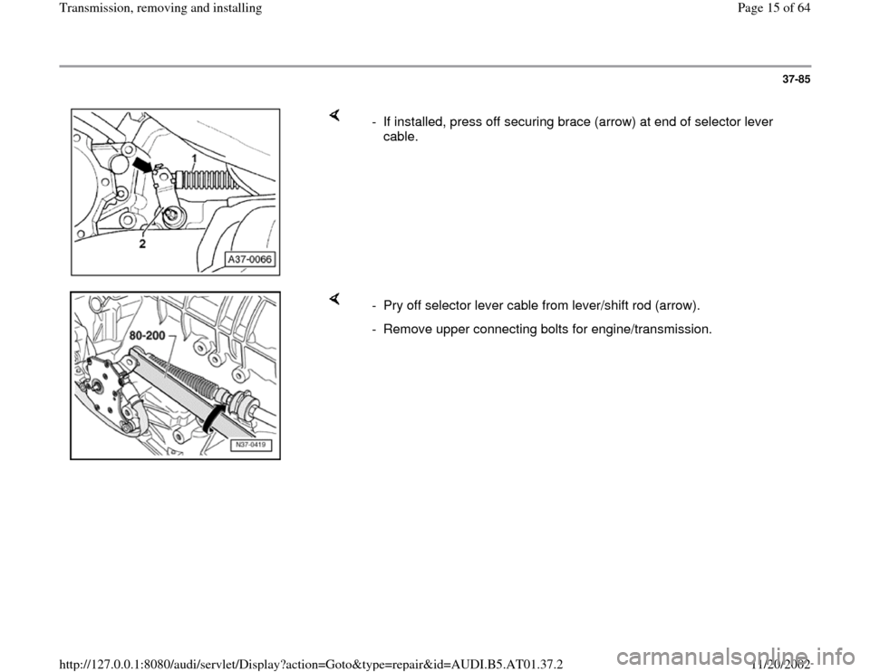
- If installed, press off securing brace (arrow) at end of selector lever
cable.
- Pry off selector lever cable from lever/shift rod (arrow).
- Remove upper connecting bolts for engine/transmission.
Pa
ge 15 of 64 Transmission, removin
g and installin
g
11/20/2002 htt
p://127.0.0.1:8080/audi/servlet/Dis
play?action=Goto&t
yp
e=re
pair&id=AUDI.B5.AT01.37.2
Page 18 of 64
37-88
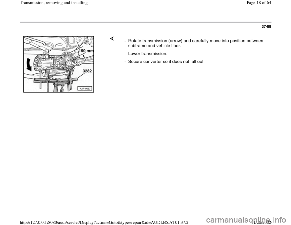
- Rotate transmission (arrow) and carefully move into position between
subframe and vehicle floor.
- Lower transmission.
- Secure converter so it does not fall out.
Pa
ge 18 of 64 Transmission, removin
g and installin
g
11/20/2002 htt
p://127.0.0.1:8080/audi/servlet/Dis
play?action=Goto&t
yp
e=re
pair&id=AUDI.B5.AT01.37.2
Page 22 of 64
37-92
- Place transmission onto transmission support.
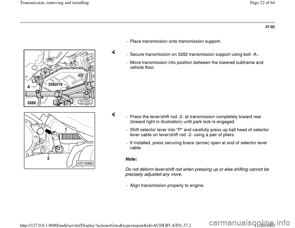
- Secure transmission on 3282 transmission support using bolt -A-.
- Move transmission into position between the lowered subframe and
vehicle floor.
Note:
Do not deform lever/shift rod when pressing up or else shifting cannot be
precisely adjusted any more. - Press the lever/shift rod -2- at transmission completely toward rear
(toward right in illustration) until park lock is engaged.
- Shift selector lever into "P" and carefully press up ball head of selector
lever cable on lever/shift rod -2- using a pair of pliers.
- If installed, press securing brace (arrow) open at end of selector lever
cable.
- Align transmission properly to engine.
Pa
ge 22 of 64 Transmission, removin
g and installin
g
11/20/2002 htt
p://127.0.0.1:8080/audi/servlet/Dis
play?action=Goto&t
yp
e=re
pair&id=AUDI.B5.AT01.37.2
Page 27 of 64
37-97
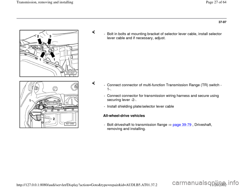
- Bolt in bolts at mounting bracket of selector lever cable, install selector
lever cable and if necessary, adjust.
All-wheel-drive vehicles - Connect connector of multi-function Transmission Range (TR) switch -
1-.
- Connect connector for transmission wiring harness and secure using
securing lever -2-.
- Install shielding plate/selector lever cable
- Bolt driveshaft to transmission flange page 39
-79
, Driveshaft,
removing and installing.
Pa
ge 27 of 64 Transmission, removin
g and installin
g
11/20/2002 htt
p://127.0.0.1:8080/audi/servlet/Dis
play?action=Goto&t
yp
e=re
pair&id=AUDI.B5.AT01.37.2
Page 32 of 64
37-102
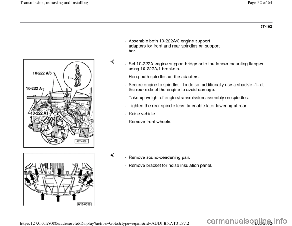
- Assemble both 10-222A/3 engine support
adapters for front and rear spindles on support
bar.
- Set 10-222A engine support bridge onto the fender mounting flanges
using 10-222A/1 brackets.
- Hang both spindles on the adapters.
- Secure engine to spindles. To do so, additionally use a shackle -1- at
the rear side of the engine to avoid damage.
- Take up weight of engine/transmission assembly on spindles.
- Tighten the rear spindle less, to enable later lowering at rear.
- Raise vehicle.
- Remove front wheels.
- Remove sound-deadening pan.
- Remove bracket for noise insulation panel.
Pa
ge 32 of 64 Transmission, removin
g and installin
g
11/20/2002 htt
p://127.0.0.1:8080/audi/servlet/Dis
play?action=Goto&t
yp
e=re
pair&id=AUDI.B5.AT01.37.2
Page 34 of 64
37-104
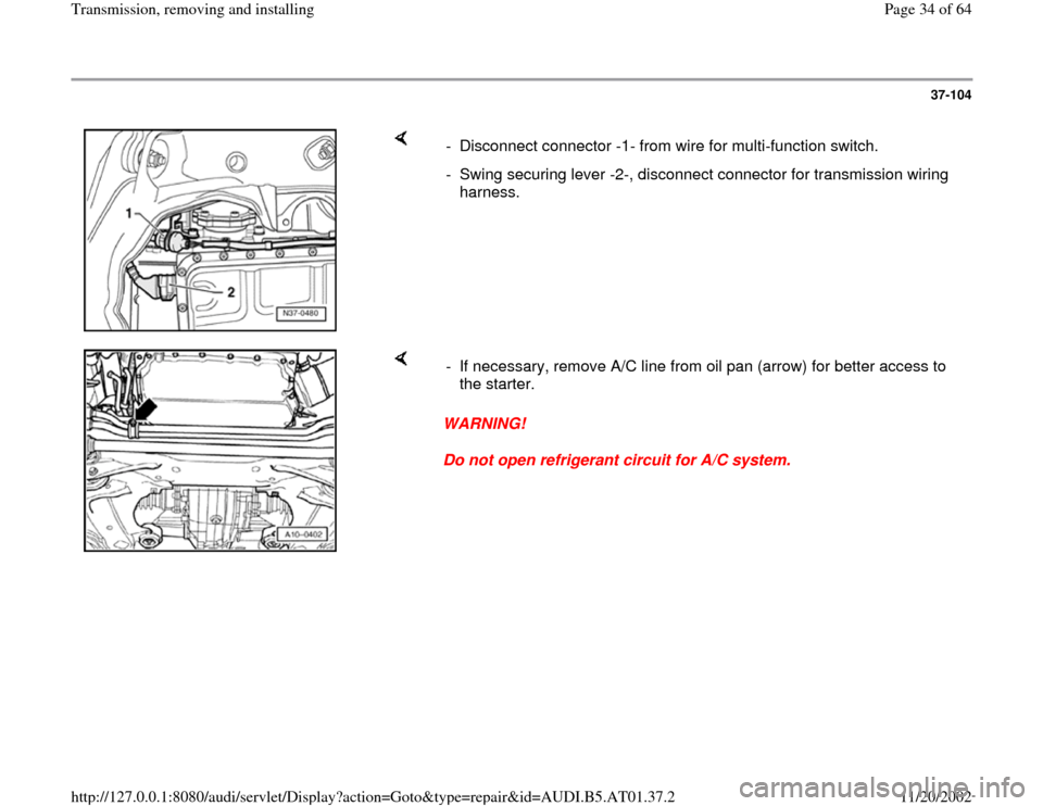
- Disconnect connector -1- from wire for multi-function switch.
- Swing securing lever -2-, disconnect connector for transmission wiring
harness.
WARNING!
Do not open refrigerant circuit for A/C system. - If necessary, remove A/C line from oil pan (arrow) for better access to
the starter.
Pa
ge 34 of 64 Transmission, removin
g and installin
g
11/20/2002 htt
p://127.0.0.1:8080/audi/servlet/Dis
play?action=Goto&t
yp
e=re
pair&id=AUDI.B5.AT01.37.2