check engine AUDI A8 2000 D2 / 1.G AHA Engine Camshaft Adjustment System Checking Workshop Manual
[x] Cancel search | Manufacturer: AUDI, Model Year: 2000, Model line: A8, Model: AUDI A8 2000 D2 / 1.GPages: 12, PDF Size: 0.09 MB
Page 1 of 12
28-29
Camshaft adjustment system,
checking
Required special tools and test equipment
VAG1551 Scan Tool (ST) with VAG1551/3
adapter cable
Multimeter US1119 (Fluke 83 or equivalent)
VW1594 connector test kit
Function
The camshaft adjustment is dependent on
engine speed and load. The electrical solenoid
valves for camshaft adjustment (-N205- and -
N208-) are switched to apply oil pressure to the
mechanical camshaft adjusters, which adjusts
the camshaft timing.
Pa
ge 1 of 12 Camshaft ad
justment s
ystem, checkin
g
11/23/2002 htt
p://127.0.0.1:8080/audi/servlet/Dis
play?action=Goto&t
yp
e=re
pair&id=AUDI.B5.FU03.28.2
Page 2 of 12
28-30
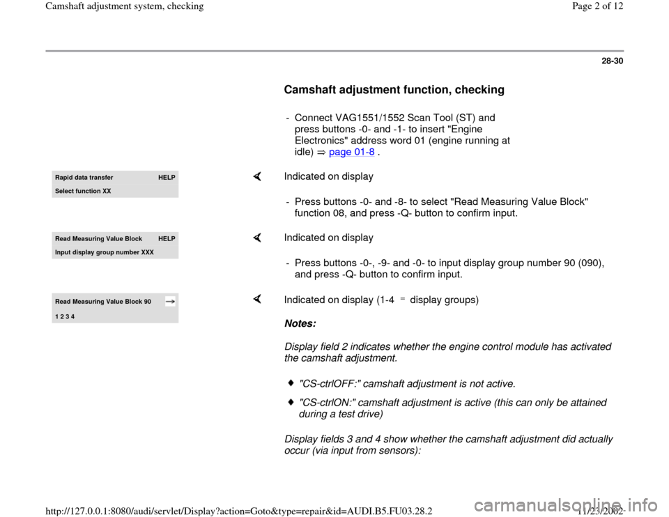
Camshaft adjustment function, checking
- Connect VAG1551/1552 Scan Tool (ST) and
press buttons -0- and -1- to insert "Engine
Electronics" address word 01 (engine running at
idle) page 01
-8 .
Rapid data transfer
HELP
Select function XX
Indicated on display
- Press buttons -0- and -8- to select "Read Measuring Value Block"
function 08, and press -Q- button to confirm input.
Read Measurin
g Value Block
HELP
Input displa
y group number XXX
Indicated on display
- Press buttons -0-, -9- and -0- to input display group number 90 (090),
and press -Q- button to confirm input.
Read Measuring Value Block 90 1 2 3 4
Indicated on display (1-4 display groups)
Notes:
Display field 2 indicates whether the engine control module has activated
the camshaft adjustment.
Display fields 3 and 4 show whether the camshaft adjustment did actually
occur (via input from sensors):
"CS-ctrlOFF:" camshaft adjustment is not active."CS-ctrlON:" camshaft adjustment is active (this can only be attained
during a test drive)
Pa
ge 2 of 12 Camshaft ad
justment s
ystem, checkin
g
11/23/2002 htt
p://127.0.0.1:8080/audi/servlet/Dis
play?action=Goto&t
yp
e=re
pair&id=AUDI.B5.FU03.28.2
Page 5 of 12
28-32
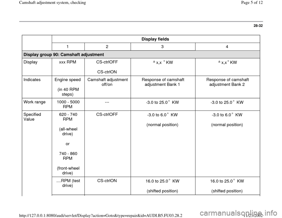
Display fields
1 2 3 4
Display group 90: Camshaft adjustment
Display xxx RPM CS-ctrlOFF
CS-ctrlON x,x KW
x,x KW
Indicates Engine speed
(in 40 RPM
steps) Camshaft adjustment
off/on Response of camshaft
adjustment Bank 1 Response of camshaft
adjustment Bank 2
Work range 1000 - 5000
RPM ---
-3.0 to 25.0 KW
-3.0 to 25.0 KW
Specified
Value 620 - 740
RPM
(all-wheel
drive)
or
740 - 860
RPM
(front-wheel
drive) CS-ctrlOFF
-3.0 to 6.0 KW
(normal position)
-3.0 to 6.0 KW
(normal position)
....RPM (test
drive) CS-ctrlON
16.0 to 25.0 KW
(shifted position)
16.0 to 25.0 KW
(shifted position)
Pa
ge 5 of 12 Camshaft ad
justment s
ystem, checkin
g
11/23/2002 htt
p://127.0.0.1:8080/audi/servlet/Dis
play?action=Goto&t
yp
e=re
pair&id=AUDI.B5.FU03.28.2
Page 7 of 12
28-33
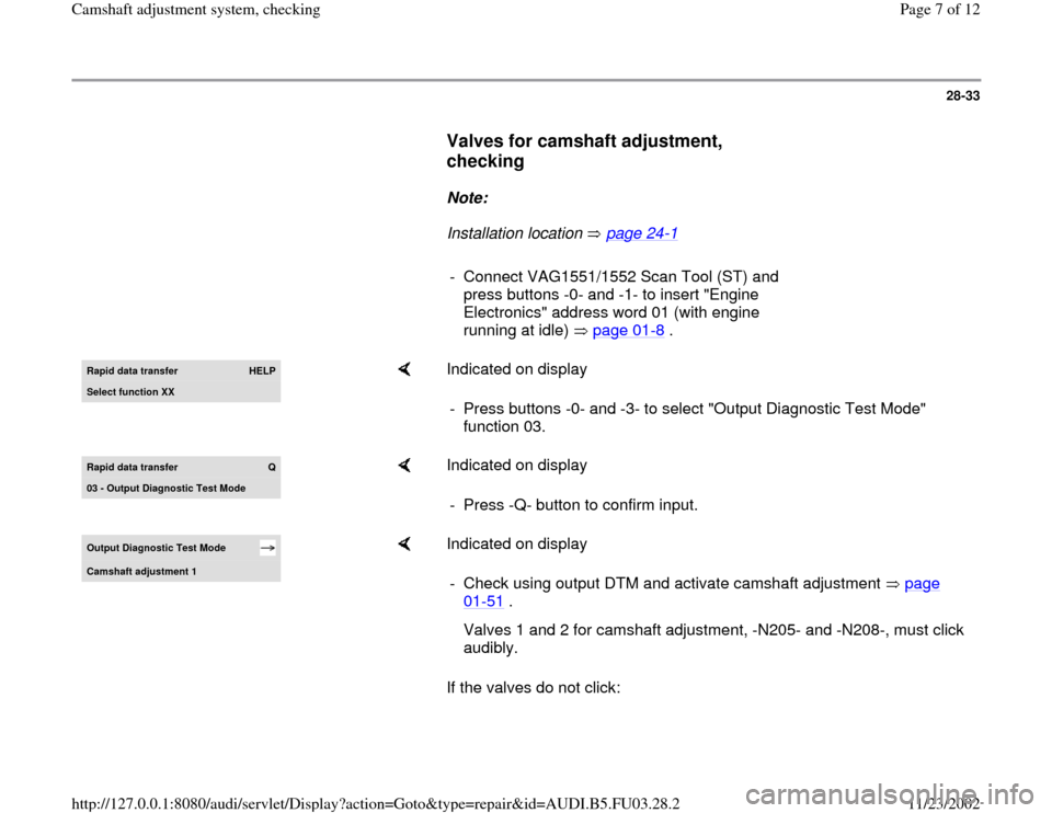
Valves for camshaft adjustment,
checking
Note:
Installation location page 24
-1
- Connect VAG1551/1552 Scan Tool (ST) and
press buttons -0- and -1- to insert "Engine
Electronics" address word 01 (with engine
running at idle) page 01
-8 .
Rapid data transfer
HELP
Select function XX
Indicated on display
- Press buttons -0- and -3- to select "Output Diagnostic Test Mode"
function 03.
Rapid data transfer
Q
03 - Output Diagnostic Test Mode
Indicated on display
- Press -Q- button to confirm input.
Output Diagnostic Test Mode Camshaft adjustment 1
Indicated on display
If the valves do not click: - Check using output DTM and activate camshaft adjustment page
01
-51
.
Valves 1 and 2 for camshaft adjustment, -N205- and -N208-, must click
audibly.
Pa
ge 7 of 12 Camshaft ad
justment s
ystem, checkin
g
11/23/2002 htt
p://127.0.0.1:8080/audi/servlet/Dis
play?action=Goto&t
yp
e=re
pair&id=AUDI.B5.FU03.28.2
Page 10 of 12
28-35
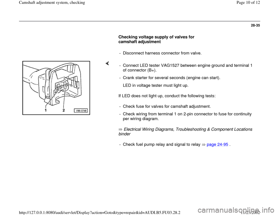
Checking voltage supply of valves for
camshaft adjustment
- Disconnect harness connector from valve.
If LED does not light up, conduct the following tests:
Electrical Wiring Diagrams, Troubleshooting & Component Locations
binder - Connect LED tester VAG1527 between engine ground and terminal 1
of connector (B+).
- Crank starter for several seconds (engine can start).
LED in voltage tester must light up.
- Check fuse for valves for camshaft adjustment.
- Check wiring from terminal 1 on 2-pin connector to fuse for continuity
per wiring diagram. - Check fuel pump relay and signal to relay page 24
-95
.
Pa
ge 10 of 12 Camshaft ad
justment s
ystem, checkin
g
11/23/2002 htt
p://127.0.0.1:8080/audi/servlet/Dis
play?action=Goto&t
yp
e=re
pair&id=AUDI.B5.FU03.28.2
Page 12 of 12
28-37
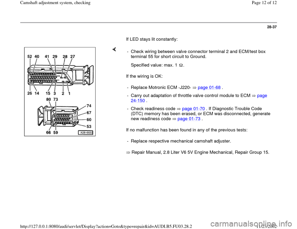
If LED stays lit constantly:
If the wiring is OK:
If no malfunction has been found in any of the previous tests:
Repair Manual, 2.8 Liter V6 5V Engine Mechanical, Repair Group 15. - Check wiring between valve connector terminal 2 and ECM/test box
terminal 55 for short circuit to Ground.
Specified value: max. 1 .- Replace Motronic ECM -J220- page 01
-68
.
- Carry out adaptation of throttle valve control module to ECM page
24
-150
.
- Check readiness code page 01
-70
. If Diagnostic Trouble Code
(DTC) memory has been erased, or ECM was disconnected, generate
new readiness code page 01
-73
.
- Replace respective mechanical camshaft adjuster.
Pa
ge 12 of 12 Camshaft ad
justment s
ystem, checkin
g
11/23/2002 htt
p://127.0.0.1:8080/audi/servlet/Dis
play?action=Goto&t
yp
e=re
pair&id=AUDI.B5.FU03.28.2