AUDI A8 2000 D2 / 1.G ATQ Engine Motronic Injection System Servicing Workshop Manual
A8 2000 D2 / 1.G
AUDI
AUDI
https://www.carmanualsonline.info/img/6/1064/w960_1064-0.png
AUDI A8 2000 D2 / 1.G ATQ Engine Motronic Injection System Servicing Workshop Manual
Page 2 of 78
disconnect connector from ignition coils and
from fuel injectors.
Pa
ge 2 of 78 Motronic in
jection s
ystem, servicin
g
11/23/2002 htt
p://127.0.0.1:8080/audi/servlet/Dis
play?action=Goto&t
yp
e=re
pair&id=AUDI.B5.FU05.24.1
Page 12 of 78
24-10
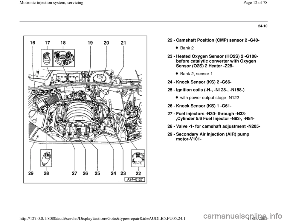
22 -
Camshaft Position (CMP) sensor 2 -G40-
Bank 2
23 -
Heated Oxygen Sensor (HO2S) 2 -G108-
before catalytic converter with Oxygen
Sensor (O2S) 2 Heater -Z28- Bank 2, sensor 1
24 -
Knock Sensor (KS) 2 -G66-
25 -
Ignition coils (-N-, -N128-, -N158-) with power output stage -N122-
26 -
Knock Sensor (KS) 1 -G61-
27 -
Fuel injectors -N30- through -N33-
,Cylinder 5/6 Fuel Injector -N83-, -N84-
28 -
Valve -1- for camshaft adjustment -N205-
29 -
Secondary Air Injection (AIR) pump
motor-V101-
Pa
ge 12 of 78 Motronic in
jection s
ystem, servicin
g
11/23/2002 htt
p://127.0.0.1:8080/audi/servlet/Dis
play?action=Goto&t
yp
e=re
pair&id=AUDI.B5.FU05.24.1
Page 49 of 78
24-41
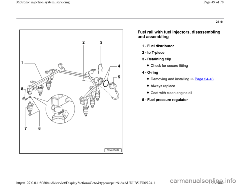
Fuel rail with fuel injectors, disassembling
and assembling
1 -
Fuel distributor
2 -
to T-piece
3 -
Retaining clip
Check for secure fitting
4 -
O-ring Removing and installing Page 24
-43
Always replaceCoat with clean engine oil
5 -
Fuel pressure regulator
Pa
ge 49 of 78 Motronic in
jection s
ystem, servicin
g
11/23/2002 htt
p://127.0.0.1:8080/audi/servlet/Dis
play?action=Goto&t
yp
e=re
pair&id=AUDI.B5.FU05.24.1
Page 50 of 78
24-42
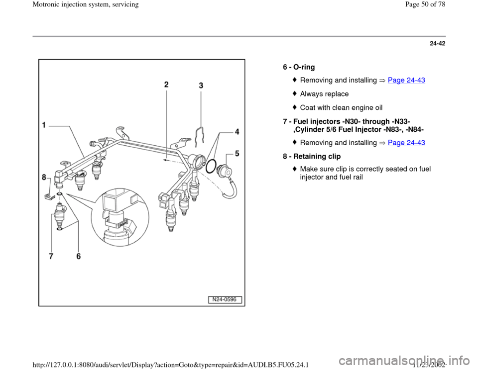
6 -
O-ring
Removing and installing Page 24
-43
Always replaceCoat with clean engine oil
7 -
Fuel injectors -N30- through -N33-
,Cylinder 5/6 Fuel Injector -N83-, -N84- Removing and installing Page 24
-43
8 -
Retaining clip
Make sure clip is correctly seated on fuel
injector and fuel rail
Pa
ge 50 of 78 Motronic in
jection s
ystem, servicin
g
11/23/2002 htt
p://127.0.0.1:8080/audi/servlet/Dis
play?action=Goto&t
yp
e=re
pair&id=AUDI.B5.FU05.24.1
Page 52 of 78
24-44
- Disengage retaining clip and remove fuel
injector.
Note:
Fuel lines must be disconnected before replacing
fuel distributor.
Installation is reverse of removal, noting the
following:
Remove O-rings at all opened connections.
(Never remove plastic cap from valve head
to replace front O-ring - pry O-ring off over
plastic cap).
Lightly lubricate O-rings with clean engine
oil.
Make sure fuel injectors are in place and
seated correctly
Check clip for unobstructed fitting.
Place fuel rail with secured fuel injectors
onto intake manifold, and apply uniform
pressure to press it in.
Tightening torque
Pa
ge 52 of 78 Motronic in
jection s
ystem, servicin
g
11/23/2002 htt
p://127.0.0.1:8080/audi/servlet/Dis
play?action=Goto&t
yp
e=re
pair&id=AUDI.B5.FU05.24.1
Page 55 of 78
24-46
Test requirement:
Fuel pressure OK, checking Page 24
-30
.
Test sequence
- Remove fuel distributor including fuel injectors
from intake manifold Page 24
-43
. Fuel lines
remain connected.
- Connect VAG1598/31 test box at wiring harness
to ECM, do not connect ECM Page 24
-17
.
- Bridge terminals 1 and 65 at test box using
adapter cables from VAG1594A connector test
kit (this step supplies Ground -GND- to one side
of relay coil for Fuel Pump -FP- relay).
Note:
Fuel Pump (FP) relay is supplied with B+ via the
central electric (terminal 30). Fuel Pump (FP)
relay receives minus via the cable bridge in test
box. The Fuel Pump (FP) is now running
constantly.
Pa
ge 55 of 78 Motronic in
jection s
ystem, servicin
g
11/23/2002 htt
p://127.0.0.1:8080/audi/servlet/Dis
play?action=Goto&t
yp
e=re
pair&id=AUDI.B5.FU05.24.1
