sensor AUDI A8 2003 D3 / 2.G Technical Features Manual
[x] Cancel search | Manufacturer: AUDI, Model Year: 2003, Model line: A8, Model: AUDI A8 2003 D3 / 2.GPages: 96, PDF Size: 5.51 MB
Page 54 of 96
Downloaded from www.Manualslib.com manuals search engine 54
Driver convenience is further enhanced, as
fewer accelerator and brake pedal operations
are required. Speed restrictions and safety
factors are reliably observed and the flow of
traffic thus better regulated.
ACC (Adaptive Cruise
Control)
Adaptive Cruise Control is a new system
designed to assist drivers and offers a much
wider range of functions than the
conventional Tempomat.
Running Gear
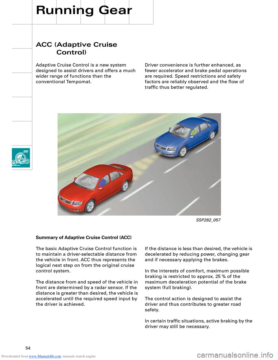
If the distance is less than desired, the vehicle is
decelerated by reducing power, changing gear
and if necessary applying the brakes.
In the interests of comfort, maximum possible
braking is restricted to approx. 25 % of the
maximum deceleration potential of the brake
system (full braking).
The control action is designed to assist the
driver and thus contributes to greater road
safety.
In certain traffic situations, active braking by the
driver may still be necessary. Summary of Adaptive Cruise Control (ACC)
The basic Adaptive Cruise Control function is
to maintain a driver-selectable distance from
the vehicle in front. ACC thus represents the
logical next step on from the original cruise
control system.
The distance from and speed of the vehicle in
front are determined by a radar sensor. If the
distance is greater than desired, the vehicle is
accelerated until the required speed input by
the driver is achieved.
SSP282_057
Page 55 of 96
Downloaded from www.Manualslib.com manuals search engine 55
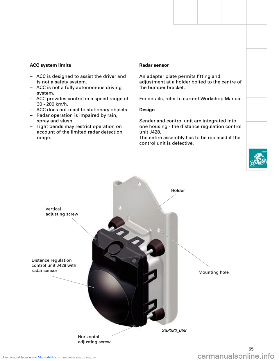
Radar sensor
An adapter plate permits fitting and
adjustment at a holder bolted to the centre of
the bumper bracket.
For details, refer to current Workshop Manual.
Design
Sender and control unit are integrated into
one housing - the distance regulation control
unit J428.
The entire assembly has to be replaced if the
control unit is defective. ACC system limits
– ACC is designed to assist the driver and
is not a safety system.
– ACC is not a fully autonomous driving
system.
– ACC provides control in a speed range of
30 - 200 km/h.
– ACC does not react to stationary objects.
– Radar operation is impaired by rain,
spray and slush.
– Tight bends may restrict operation on
account of the limited radar detection
range.
SSP282_058
Vertical
adjusting screwHolder
Distance regulation
control unit J428 with
radar sensor
Horizontal
adjusting screwMounting hole
Page 64 of 96
Downloaded from www.Manualslib.com manuals search engine 64
Electrical System
Convenience and security
electronics
"Advanced Key" entry and start
authorisation system
"Advanced Key" can be taken to mean an
"advanced locking and security system".
It takes the form of a non-contacting key
recognition system. With the "Advanced Key"
package, the "Vehicle unlocking" and "Vehicle
locking" functions by way of a mechanical or
remote control key are supplemented by the non-
contacting functions "Vehicle unlocking" and
"Vehicle locking".
Functions
Advanced Key "unlocking"
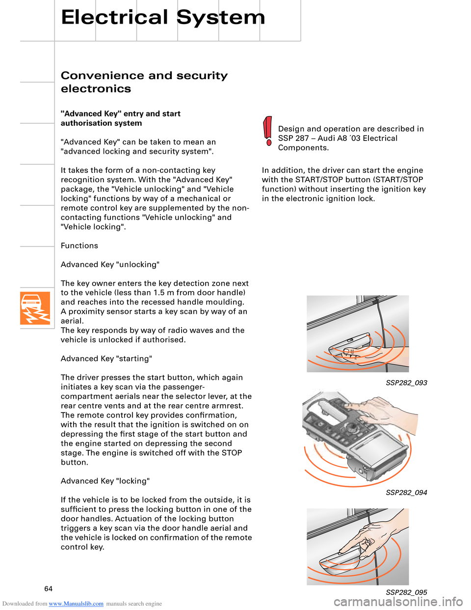
The key owner enters the key detection zone next
to the vehicle (less than 1.5 m from door handle)
and reaches into the recessed handle moulding.
aerial.
The key responds by way of radio waves and the
vehicle is unlocked if authorised.
Advanced Key "starting"
The driver presses the start button, which again
initiates a key scan via the passenger-
compartment aerials near the selector lever, at the
rear centre vents and at the rear centre armrest.
The remote control key provides confirmation,
with the result that the ignition is switched on on
depressing the first stage of the start button and
the engine started on depressing the second
stage. The engine is switched off with the STOP
button.
Advanced Key "locking"
If the vehicle is to be locked from the outside, it is
sufficient to press the locking button in one of the
door handles. Actuation of the locking button
triggers a key scan via the door handle aerial and
the vehicle is locked on confirmation of the remote
control key.In addition, the driver can start the engine
with the START/STOP button (START/STOP
function) without inserting the ignition key
in the electronic ignition lock.
SSP282_093
SSP282_094
SSP282_095
Design and operation are described in
SSP 287 – Audi A8 ´03 Electrical
Components.
A proximity sensor starts a key scan by way of an
Page 68 of 96
Downloaded from www.Manualslib.com manuals search engine 68
Electrical System
The headlight in the Audi A8 ´03 combines both
design elements and innovative technology.
Headlight versions:
– Basic halogen version H7
Dynamic headlight range control is not
necessary with halogen headlights. The air
suspension provides compensation for static
load statuses and a thumbwheel is therefore
also not required.
– Bi-xenon version
– Bi-xenon version with integrated adaptive
light function
The headlight range control unit J431 is
responsible for providing static and dynamic
compensation for vehicle tilting as well as
actuation of the static adaptive light
function. The sensor signals of the 4-level air
suspension system are picked off by the
drive system CAN for control purposes. A
distinction is made between the two
gas-discharge lamp versions by way of
appropriate encoding (1 or 2) at the
headlight range control unit.
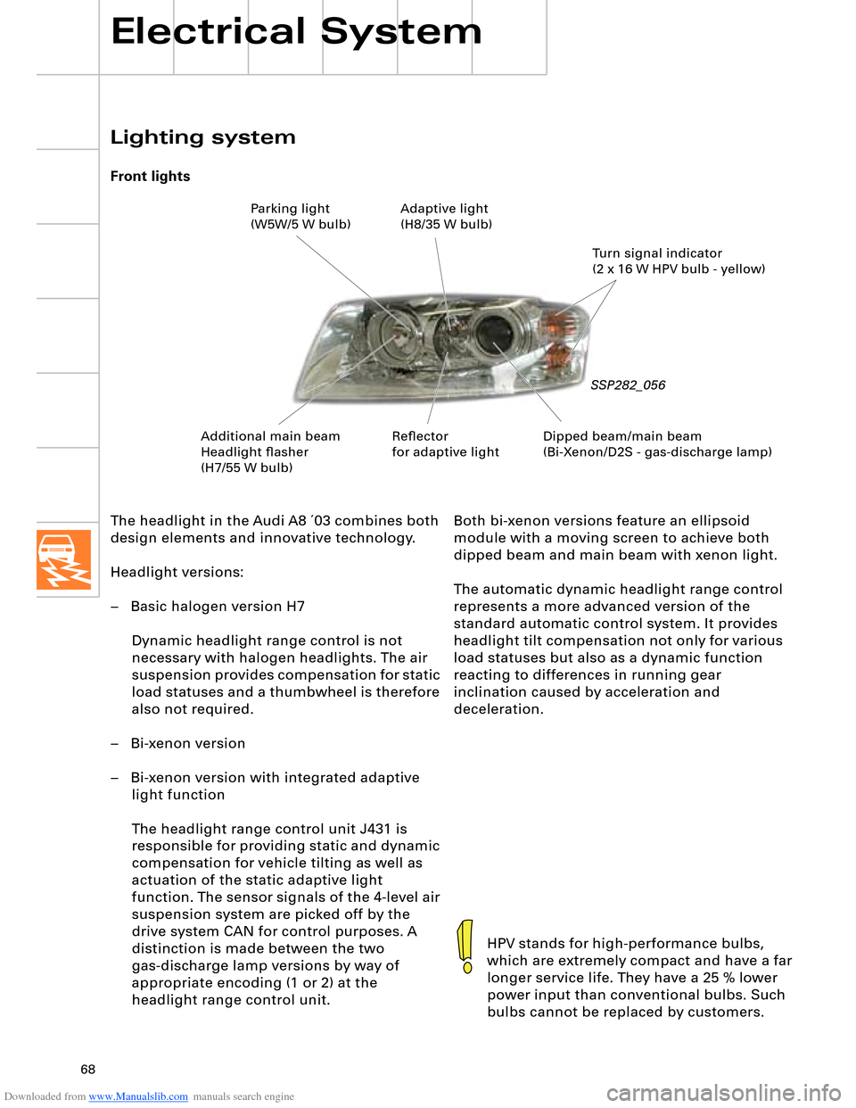
Lighting system
Front lights
SSP282_056
HPV stands for high-performance bulbs,
which are extremely compact and have a far
longer service life. They have a 25 % lower
power input than conventional bulbs. Such
bulbs cannot be replaced by customers.
Both bi-xenon versions feature an ellipsoid
module with a moving screen to achieve both
dipped beam and main beam with xenon light.
The automatic dynamic headlight range control
represents a more advanced version of the
standard automatic control system. It provides
headlight tilt compensation not only for various
load statuses but also as a dynamic function
reacting to differences in running gear
inclination caused by acceleration and
deceleration.
Dipped beam/main beam
(Bi-Xenon/D2S - gas-discharge lamp)Turn signal indicator
(2 x 16 W HPV bulb - yellow) Parking light
(W5W/5 W bulb)Adaptive light
(H8/35 W bulb)
Additional main beam
Headlight flasher
(H7/55 W bulb)Reflector
for adaptive light
Page 70 of 96
Downloaded from www.Manualslib.com manuals search engine 70
Electrical System
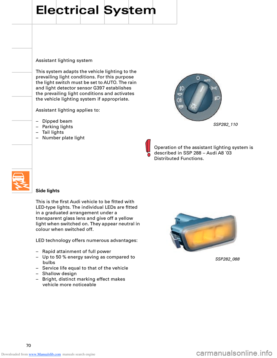
Side lights
This is the first Audi vehicle to be fitted with
LED-type lights. The individual LEDs are fitted
in a graduated arrangement under a
transparent glass lens and give off a yellow
light when switched on. They appear neutral in
colour when switched off.
LED technology offers numerous advantages:
– Rapid attainment of full power
– Up to 50 % energy saving as compared to
bulbs
– Service life equal to that of the vehicle
– Shallow design
– Bright, distinct marking effect makes
vehicle more noticeable
SSP282_088
Assistant lighting system
This system adapts the vehicle lighting to the
prevailing light conditions. For this purpose
the light switch must be set to AUTO. The rain
and light detector sensor G397 establishes
the prevailing light conditions and activates
the vehicle lighting system if appropriate.
Assistant lighting applies to:
– Dipped beam
– Parking lights
– Tail lights
– Number plate light
Operation of the assistant lighting system is
described in SSP 288 – Audi A8 ´03
Distributed Functions.
SSP282_110
Page 74 of 96
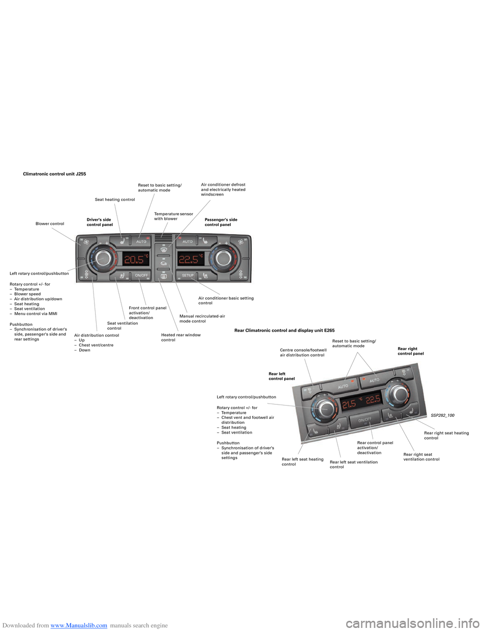
Downloaded from www.Manualslib.com manuals search engine Climatronic control unit J255
SSP282_100
Rear Climatronic control and display unit E265
Air conditioner basic setting
control
Heated rear window
control Front control panel
activation/
deactivation
Seat ventilation
control
Air distribution control
– Up
– Chest vent/centre
– Down Left rotary control/pushbutton
Rotary control +/- for
– Temperature
– Blower speed
– Air distribution up/down
– Seat heating
– Seat ventilation
– Menu control via MMI
Pushbutton
– Synchronisation of driver's
side, passenger's side and
rear settingsDriver's side
control panelPassenger's side
control panel Seat heating controlReset to basic setting/
automatic mode
Temperature sensor
with blowerAir conditioner defrost
and electrically heated
windscreen
Manual recirculated-air
mode control Blower control
Rear left
control panelCentre console/footwell
air distribution controlReset to basic setting/
automatic mode
Rear right
control panel
Left rotary control/pushbutton
Rotary control +/- for
– Temperature
– Chest vent and footwell air
distribution
– Seat heating
– Seat ventilation
Pushbutton
– Synchronisation of driver's
side and passenger's side
settings
Rear left seat heating
controlRear control panel
activation/
deactivation
Rear right seat
ventilation controlRear right seat heating
control
Rear left seat ventilation
control
Page 76 of 96
Downloaded from www.Manualslib.com manuals search engine 76
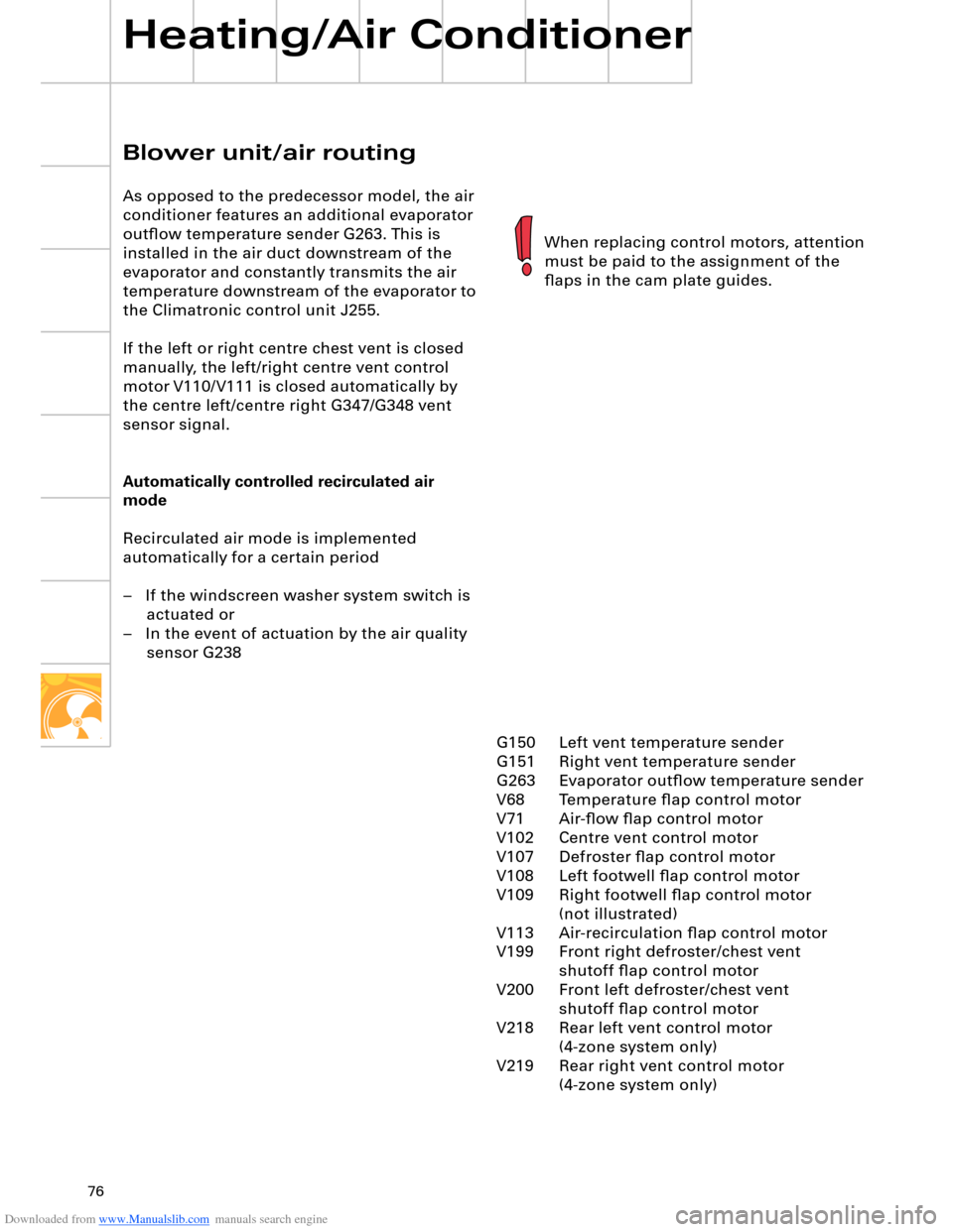
Blower unit/air routing
As opposed to the predecessor model, the air
conditioner features an additional evaporator
outflow temperature sender G263. This is
installed in the air duct downstream of the
evaporator and constantly transmits the air
temperature downstream of the evaporator to
the Climatronic control unit J255.
If the left or right centre chest vent is closed
manually, the left/right centre vent control
motor V110/V111 is closed automatically by
the centre left/centre right G347/G348 vent
sensor signal.
Automatically controlled recirculated air
mode
Recirculated air mode is implemented
automatically for a certain period
– If the windscreen washer system switch is actuated or
– In the event of actuation by the air quality sensor G238
Heating/Air Conditioner
When replacing control motors, attention
must be paid to the assignment of the
flaps in the cam plate guides.
G150 Left vent temperature sender
G151 Right vent temperature sender
G263 Evaporator outflow temperature sender
V68
V71 Air-flow flap control motor
V102 Centre vent control motor
V107 Defroster flap control motor
V108 Left footwell flap control motor
V109 Right footwell flap control motor (not illustrated)
V113 Air-recirculation flap control motor
V199 Front right defroster/chest vent shutoff flap control motor
V200 Front left defroster/chest vent shutoff flap control motor
V218 Rear left vent control motor (4-zone system only)
V219 Rear right vent control motor (4-zone system only)Temperature flap control motor
Page 80 of 96
Downloaded from www.Manualslib.com manuals search engine 80
Heating/Air Conditioner
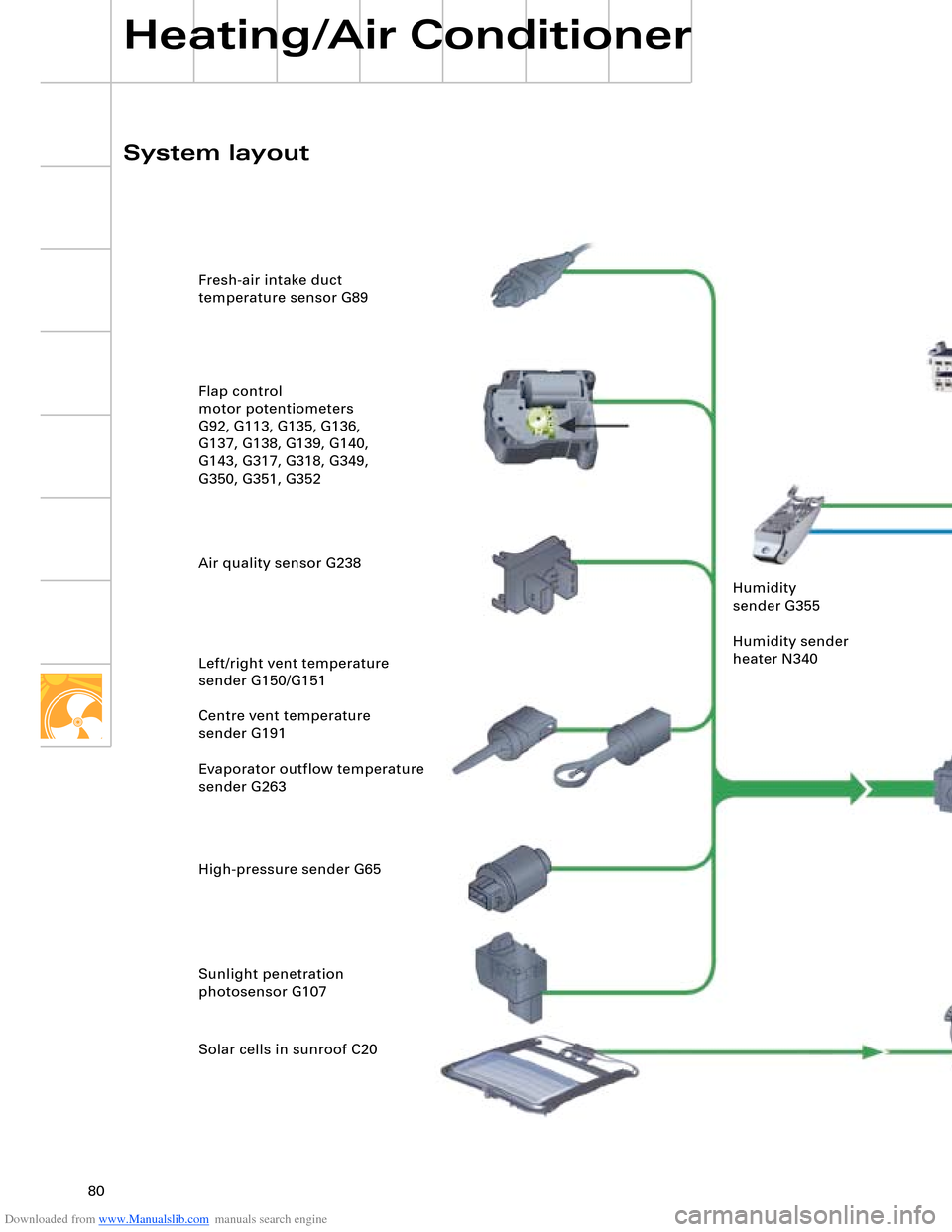
SSP282_103 Fresh-air intake duct
temperature sensor G89
Flap control
motor potentiometers
G92, G113, G135, G136,
G137, G138, G139, G140,
G143, G317, G318, G349,
G350, G351, G352
Air quality sensor G238
Left/right vent temperature
sender G150/G151
Centre vent temperature
sender G191
Evaporator outflow temperature
sender G263
High-pressure sender G65
Sunlight penetration
photosensor G107
Solar cells in sunroof C20
System layoutControl unit with display
in dash panel insert J285
MOST busFront information display and
operating unit control unit J523
Rear right footwell heater
element Z43 Rear left footwell heater
element Z42 Fresh-air blower control unit
J126 with fresh-air blower V2Diagnosis CAN
Data bus diagnostic
interface J533
Sunroof electronics
control unit J528 Humidity
sender G355
Humidity sender
heater N340
Climatronic
control unit J255
Convenience CAN
Additional heater
control unit J364 Rear Climatronic control
and display unit E265Energy management
control unit J644Drive system CANEngine control unit J623Front information and display and
operating unit control unit J685
Radiator fan
control unit J293
Radiator fan V7
Air conditioning system compressor regulating valve N280
Flap control motors
V68, V71, V102, V107, V108, V109,
V110, V111, V113, V199, V200, V220,
V218, V219, V221
Coolant circulation pump V50
Left/right heat regulation valve N175/N176
Heated windscreen control unit J505
Heated windscreen Z2
Driver seat/front passenger seat ventilation control unit
J672/J673
Front left/front right heated seat Z45/Z46
Temperature sender for front left/front right seat
G344/G345
Page 81 of 96
Downloaded from www.Manualslib.com manuals search engine 80
Heating/Air Conditioner
SSP282_103 Fresh-air intake duct
temperature sensor G89
Flap control
motor potentiometers
G92, G113, G135, G136,
G137, G138, G139, G140,
G143, G317, G318, G349,
G350, G351, G352
Air quality sensor G238
Left/right vent temperature
sender G150/G151
Centre vent temperature
sender G191
Evaporator outflow temperature
sender G263
High-pressure sender G65
Sunlight penetration
photosensor G107
Solar cells in sunroof C20
System layoutControl unit with display
in dash panel insert J285
MOST busFront information display and
operating unit control unit J523
Rear right footwell heater
element Z43 Rear left footwell heater
element Z42 Fresh-air blower control unit
J126 with fresh-air blower V2Diagnosis CAN
Data bus diagnostic
interface J533
Sunroof electronics
control unit J528 Humidity
sender G355
Humidity sender
heater N340
Climatronic
control unit J255
Convenience CAN
Additional heater
control unit J364 Rear Climatronic control
and display unit E265Energy management
control unit J644Drive system CANEngine control unit J623Front information and display and
operating unit control unit J685
Radiator fan
control unit J293
Radiator fan V7
Air conditioning system compressor regulating valve N280
Flap control motors
V68, V71, V102, V107, V108, V109,
V110, V111, V113, V199, V200, V220,
V218, V219, V221
Coolant circulation pump V50
Left/right heat regulation valve N175/N176
Heated windscreen control unit J505
Heated windscreen Z2
Driver seat/front passenger seat ventilation control unit
J672/J673
Front left/front right heated seat Z45/Z46
Temperature sender for front left/front right seat
G344/G345
Page 83 of 96
Downloaded from www.Manualslib.com manuals search engine 83
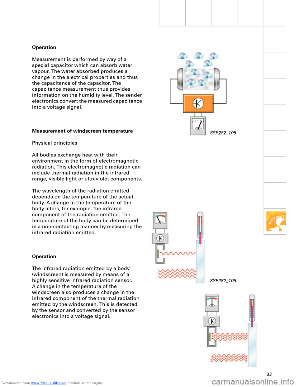
Operation
Measurement is performed by way of a
special capacitor which can absorb water
vapour. The water absorbed produces a
change in the electrical properties and thus
the capacitance of the capacitor. The
capacitance measurement thus provides
information on the humidity level. The sender
electronics convert the measured capacitance
into a voltage signal.
Measurement of windscreen temperature
Physical principles
All bodies exchange heat with their
environment in the form of electromagnetic
radiation. This electromagnetic radiation can
include thermal radiation in the infrared
range, visible light or ultraviolet components.
The wavelength of the radiation emitted
depends on the temperature of the actual
body. A change in the temperature of the
body alters, for example, the infrared
component of the radiation emitted. The
temperature of the body can be determined
in a non-contacting manner by measuring the
infrared radiation emitted.
Operation
The infrared radiation emitted by a body
(windscreen) is measured by means of a
highly sensitive infrared radiation sensor.
A change in the temperature of the
windscreen also produces a change in the
infrared component of the thermal radiation
emitted by the windscreen. This is detected
by the sensor and converted by the sensor
electronics into a voltage signal.
SSP282_105
SSP282_106