Butt AUDI A8 2003 D3 / 2.G Technical Features Manual
[x] Cancel search | Manufacturer: AUDI, Model Year: 2003, Model line: A8, Model: AUDI A8 2003 D3 / 2.GPages: 96, PDF Size: 5.51 MB
Page 11 of 96
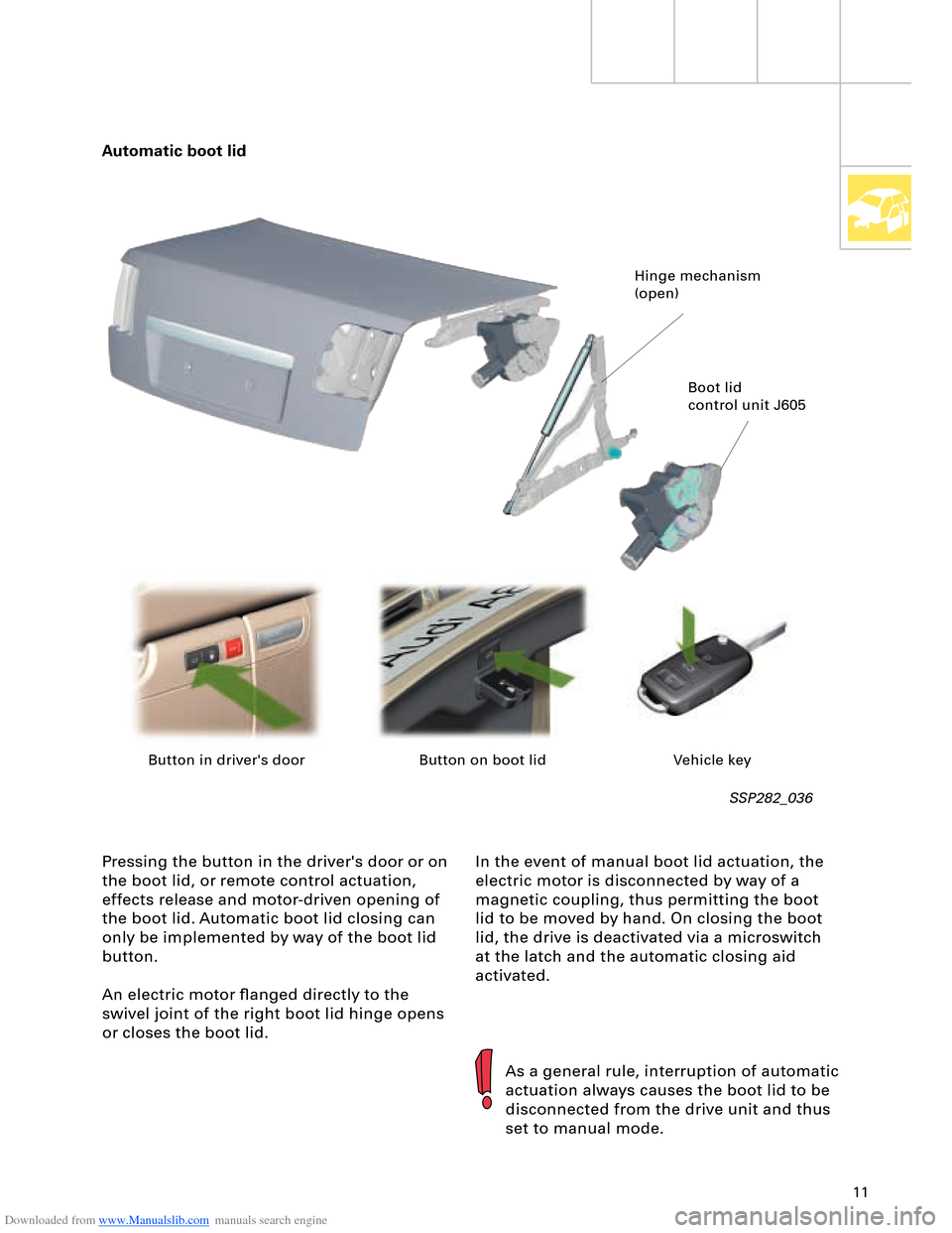
Downloaded from www.Manualslib.com manuals search engine 11
In the event of manual boot lid actuation, the
electric motor is disconnected by way of a
magnetic coupling, thus permitting the boot
lid to be moved by hand. On closing the boot
lid, the drive is deactivated via a microswitch
at the latch and the automatic closing aid
activated. Pressing the button in the driver's door or on
the boot lid, or remote control actuation,
effects release and motor-driven opening of
the boot lid. Automatic boot lid closing can
only be implemented by way of the boot lid
button.
An electric motor flanged directly to the
swivel joint of the right boot lid hinge opens
or closes the boot lid.
SSP282_036
Automatic boot lid
As a general rule, interruption of automatic
actuation always causes the boot lid to be
disconnected from the drive unit and thus
set to manual mode.
Hinge mechanism
(open)
Boot lid
control unit J605
Button in driver's door Button on boot lid Vehicle key
Page 41 of 96
Downloaded from www.Manualslib.com manuals search engine 41
Automatically controlled
starting
The automatic start control is integrated into
the engine control unit.
A new feature is that starter control is no
longer implemented by way of the ignition/
starter switch D (switching of terminal 50),
but rather it is performed automatically by
the engine control unit.
Release for starter actuation is always
transmitted by the entry and start
authorisation control unit J518 to the engine
control unit J623.
In addition to general release by the
immobilizer, the following start release
conditions also have to be satisfied:
– Start signal from entry and start
authorisation switch E415 or entry and
start authorisation button E408
– Clutch pedal pressed, signal from clutch
pedal switch F194 (manual gearbox only)
– Selector lever position P or N (automatic
gearbox control unit J217)
– In the event of start signal via entry and
start authorisation button E408, brake
must be pressed (signal from brake light
switch F via separate interface)
As a safeguard, P/N signal or signal from
clutch pedal switch F194 must be applied
to the separate interfaces of the two
control units (J623 and J518).
Additional safeguard, as entry and start
authorisation button E408 can be
actuated by front passenger.
1
2 1
1
2
Page 42 of 96
Downloaded from www.Manualslib.com manuals search engine 42
Engine, Mechanics
Sequence of operations
1 Entry and start authorisation switch E415/entry and start authorisation button E408
2 Entry and start authorisation control unit J518
The entry and start authorisation control
unit checks for authorisation – in the form
of information on selector slide position N
or P – from the automatic gearbox control
unit J217 and for brake application in the
case of a start signal from the entry and
start authorisation button E408.
3 Engine control unit J623 Application of selector slide position P/N or
"clutch pressed" information to the engine
control unit (separate interface) causes the
two starter relays J53 and J695 to be
actuated simultaneously. The relays then
switch terminal 50 for starter actuation.
The starter operates and cranks the engine.
On exceeding a defined engine speed, the
engine control unit J623 recognises that
the engine has started and the relays are
deenergised (thus terminating starting
process).
As a safeguard, two relays are connected in
series. In the event of fusion welding of the
make contacts (relay remains closed
following deenergisation), the engine
control unit J623 can thus interrupt the
circuit (terminal 50) by way of the other
relay in each case.
The two relays are deenergised alternately
in order to ensure even make contact wear
(break spark) in both relays. The
deenergisation sequence alternates. The driver triggers a brief start signal
(min. 20 ms) by turning the ignition key to
start position or by pressing the entry and
start authorisation button E408.
If the start prerequisites have been
satisfied, the entry and start authorisation
control unit J518 transmits a start request
– terminal 50 ON – to the engine control
unit J623.
The entry and start authorisation control unit J518 also controls the terminal 15 and
terminal 75x circuits.
Relay operation is monitored and faults diagnosed by evaluating the alternating
deenergisation with the aid of the terminal
50R interface.
The terminal 50R interface represents a link
with terminal 50 and provides the engine
control unit J623 with feedback for start
control/diagnosis.
Automatically controlled starting is not
permitted in the event of undervoltage or a
system fault.
The engine can however be started
manually by way of corresponding start
signal actuation.
To relieve the load on the starter and
battery, the relay actuation time is
limited to approx. 10 seconds per starting
operation (automatic or manual starting).
Page 43 of 96
Downloaded from www.Manualslib.com manuals search engine 43
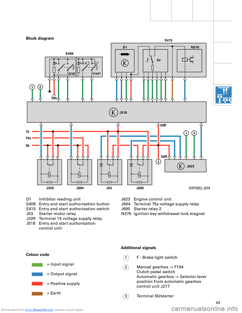
D1
30
15
J329J53J695J694
75xE415
N376
6x
J623
J518
50R
50R
3
12
12
E408
STOP START
58s
210 210
D1 Inhibitor reading unit
E408 Entry and start authorisation button
E415 Entry and start authorisation switch
J53 Starter motor relay
J329 Terminal 15 voltage supply relay
J518 Entry and start authorisation
control unit Block diagram
SSP282_024
Colour code
= Input signal
= Output signal
= Positive supply
= Earth
J623 Engine control unit
J694 Terminal 75x voltage supply relay
J695 Starter relay 2
N376 Ignition key withdrawal lock magnet
Additional signals
F - Brake light switch
Manual gearbox -> F194
Clutch pedal switch
Automatic gearbox -> Selector lever
position from automatic gearbox
control unit J217
Terminal 50/starter
1
2
3
Page 48 of 96
Downloaded from www.Manualslib.com manuals search engine 48
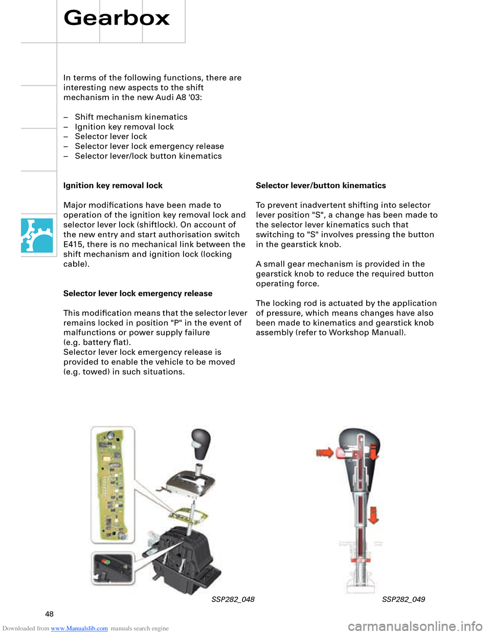
Selector lever/button kinematics
To prevent inadvertent shifting into selector
lever position "S", a change has been made to
the selector lever kinematics such that
switching to "S" involves pressing the button
in the gearstick knob.
A small gear mechanism is provided in the
gearstick knob to reduce the required button
operating force.
The locking rod is actuated by the application
of pressure, which means changes have also
been made to kinematics and gearstick knob
assembly (refer to Workshop Manual).
In terms of the following functions, there are
interesting new aspects to the shift
mechanism in the new Audi A8 '03:
– Shift mechanism kinematics
– Ignition key removal lock
– Selector lever lock
– Selector lever lock emergency release
– Selector lever/lock button kinematics
Ignition key removal lock
Major modifications have been made to
operation of the ignition key removal lock and
selector lever lock (shiftlock). On account of
the new entry and start authorisation switch
E415, there is no mechanical link between the
shift mechanism and ignition lock (locking
cable).
Selector lever lock emergency release
This modification means that the selector lever
remains locked in position "P" in the event of
malfunctions or power supply failure
(e.g. battery flat).
Selector lever lock emergency release is
provided to enable the vehicle to be moved
(e.g. towed) in such situations.
Gearbox
SSP282_048 SSP282_049
Page 53 of 96
Downloaded from www.Manualslib.com manuals search engine 53
The following functions are provided by the
electric parking brake:
– Parking brake function
– Emergency braking function
– Holding function when driving off on a hill
– Brake pad wear indicator
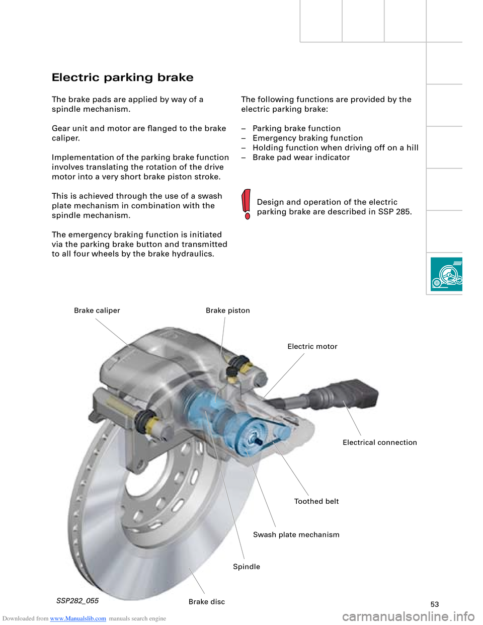
Electric parking brake
The brake pads are applied by way of a
spindle mechanism.
Gear unit and motor are flanged to the brake
caliper.
Implementation of the parking brake function
involves translating the rotation of the drive
motor into a very short brake piston stroke.
This is achieved through the use of a swash
plate mechanism in combination with the
spindle mechanism.
The emergency braking function is initiated
via the parking brake button and transmitted
to all four wheels by the brake hydraulics.
Design and operation of the electric
parking brake are described in SSP 285.
SSP282_055
Toothed belt
Swash plate mechanismElectric motor Brake piston
SpindleElectrical connection
Brake disc Brake caliper
Page 56 of 96
Downloaded from www.Manualslib.com manuals search engine 56
SSP282_061
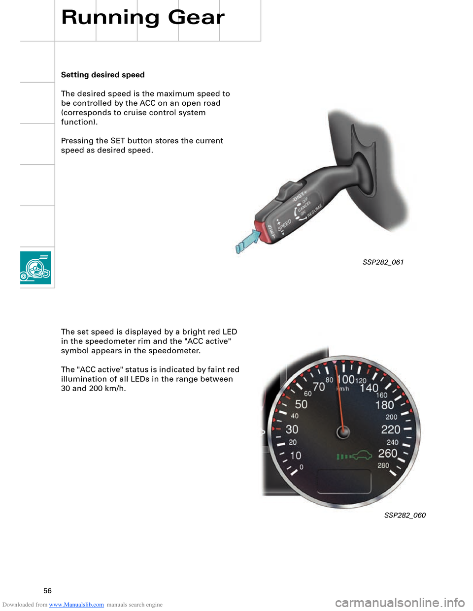
Setting desired speed
The desired speed is the maximum speed to
be controlled by the ACC on an open road
(corresponds to cruise control system
function).
Pressing the SET button stores the current
speed as desired speed.
Running Gear
The set speed is displayed by a bright red LED
in the speedometer rim and the "ACC active"
symbol appears in the speedometer.
The "ACC active" status is indicated by faint red
illumination of all LEDs in the range between
30 and 200 km/h.
SSP282_060
Page 57 of 96
Downloaded from www.Manualslib.com manuals search engine 57
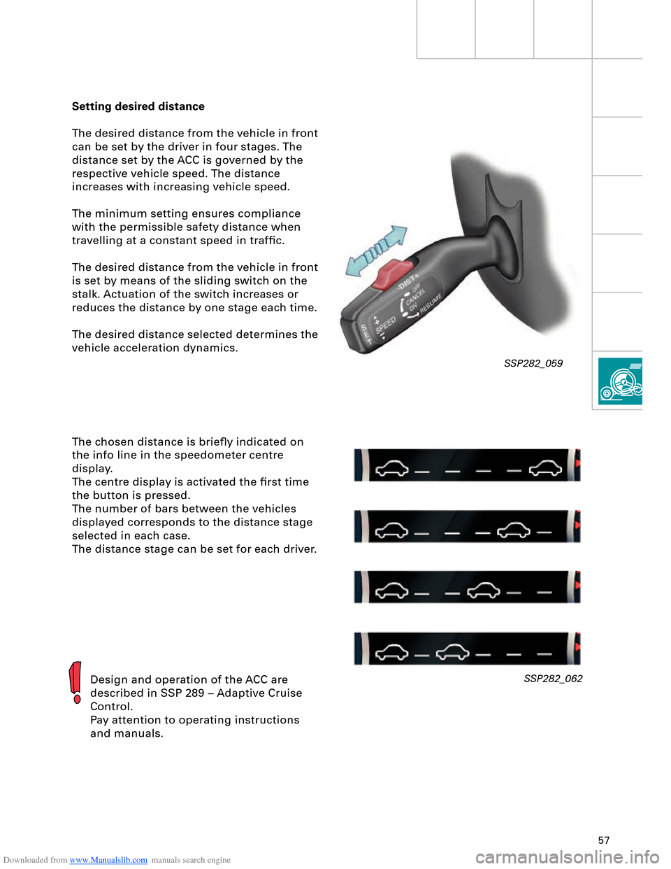
Setting desired distance
The desired distance from the vehicle in front
can be set by the driver in four stages. The
distance set by the ACC is governed by the
respective vehicle speed. The distance
increases with increasing vehicle speed.
The minimum setting ensures compliance
with the permissible safety distance when
travelling at a constant speed in traffic.
The desired distance from the vehicle in front
is set by means of the sliding switch on the
stalk. Actuation of the switch increases or
reduces the distance by one stage each time.
The desired distance selected determines the
vehicle acceleration dynamics.
The chosen distance is briefly indicated on
the info line in the speedometer centre
display.
The centre display is activated the first time
the button is pressed.
The number of bars between the vehicles
displayed corresponds to the distance stage
selected in each case.
The distance stage can be set for each driver.
Design and operation of the ACC are
described in SSP 289 – Adaptive Cruise
Control.
Pay attention to operating instructions
and manuals.SSP282_062
SSP282_059
Page 64 of 96
Downloaded from www.Manualslib.com manuals search engine 64
Electrical System
Convenience and security
electronics
"Advanced Key" entry and start
authorisation system
"Advanced Key" can be taken to mean an
"advanced locking and security system".
It takes the form of a non-contacting key
recognition system. With the "Advanced Key"
package, the "Vehicle unlocking" and "Vehicle
locking" functions by way of a mechanical or
remote control key are supplemented by the non-
contacting functions "Vehicle unlocking" and
"Vehicle locking".
Functions
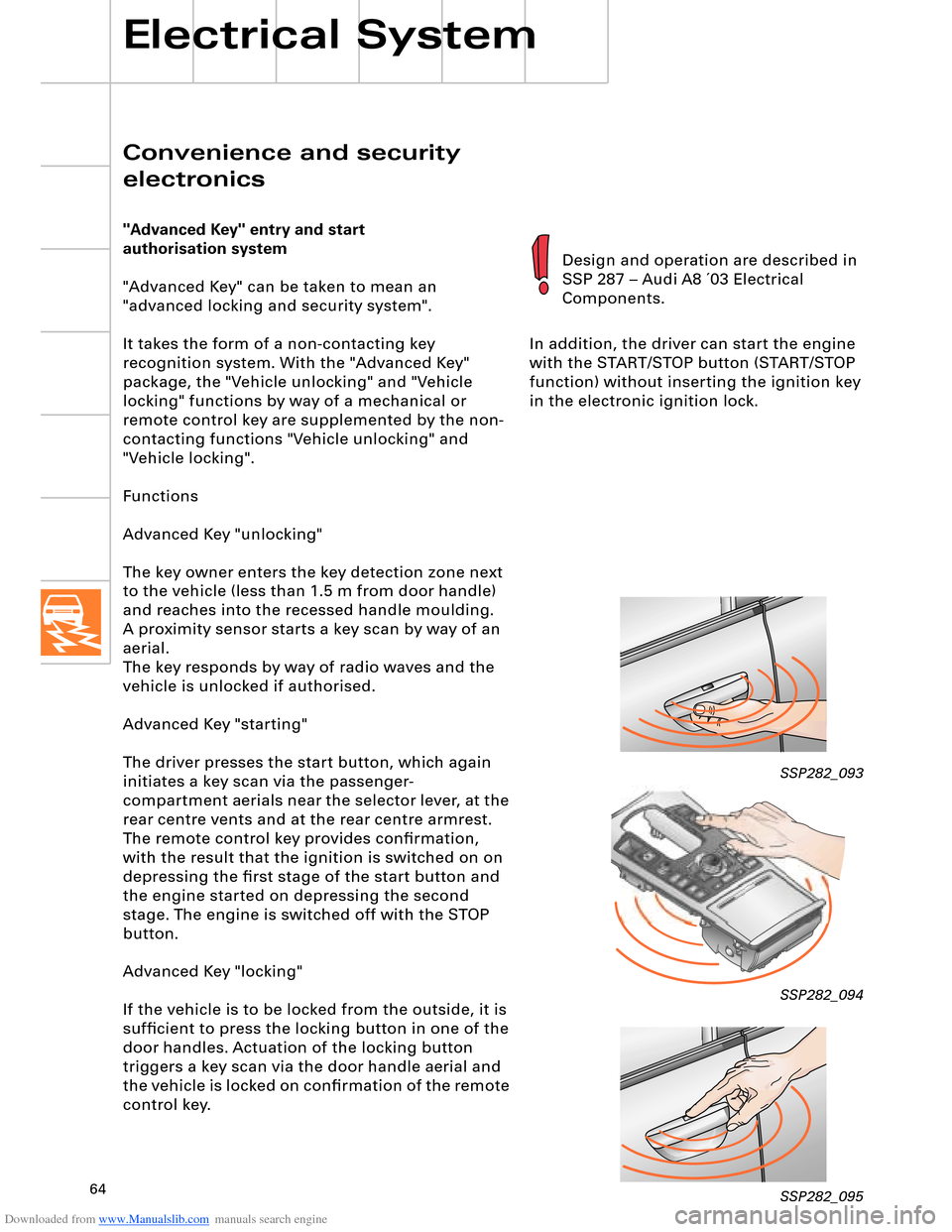
Advanced Key "unlocking"
The key owner enters the key detection zone next
to the vehicle (less than 1.5 m from door handle)
and reaches into the recessed handle moulding.
aerial.
The key responds by way of radio waves and the
vehicle is unlocked if authorised.
Advanced Key "starting"
The driver presses the start button, which again
initiates a key scan via the passenger-
compartment aerials near the selector lever, at the
rear centre vents and at the rear centre armrest.
The remote control key provides confirmation,
with the result that the ignition is switched on on
depressing the first stage of the start button and
the engine started on depressing the second
stage. The engine is switched off with the STOP
button.
Advanced Key "locking"
If the vehicle is to be locked from the outside, it is
sufficient to press the locking button in one of the
door handles. Actuation of the locking button
triggers a key scan via the door handle aerial and
the vehicle is locked on confirmation of the remote
control key.In addition, the driver can start the engine
with the START/STOP button (START/STOP
function) without inserting the ignition key
in the electronic ignition lock.
SSP282_093
SSP282_094
SSP282_095
Design and operation are described in
SSP 287 – Audi A8 ´03 Electrical
Components.
A proximity sensor starts a key scan by way of an
Page 65 of 96
Downloaded from www.Manualslib.com manuals search engine 65
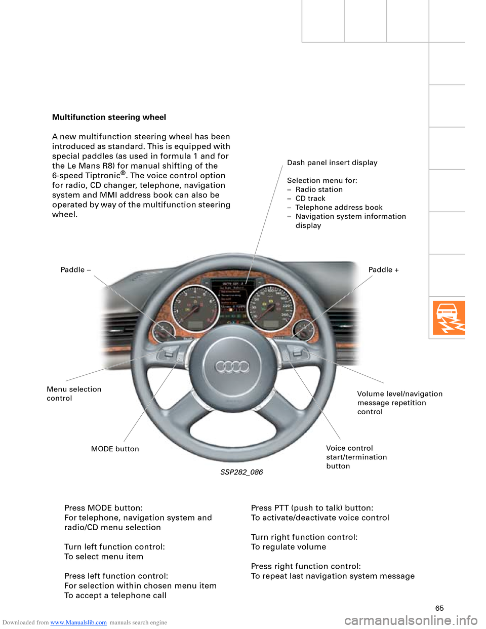
Multifunction steering wheel
A new multifunction steering wheel has been
introduced as standard. This is equipped with
special paddles (as used in formula 1 and for
the Le Mans R8) for manual shifting of the
6-speed Tiptronic
®. The voice control option
for radio, CD changer, telephone, navigation
system and MMI address book can also be
operated by way of the multifunction steering
wheel.
Dash panel insert display
Selection menu for:
– Radio station
– CD track
– Telephone address book
– Navigation system information
display
SSP282_086
Press MODE button:
For telephone, navigation system and
radio/CD menu selection
Turn left function control:
To select menu item
Press left function control:
For selection within chosen menu item
To accept a telephone callPress PTT (push to talk) button:
To activate/deactivate voice control
Turn right function control:
To regulate volume
Press right function control:
To repeat last navigation system message
Volume level/navigation
message repetition
control
Voice control
start/termination
button MODE button Menu selection
controlPaddle –Paddle +