Power AUDI A8 2003 D3 / 2.G Technical Features Manual
[x] Cancel search | Manufacturer: AUDI, Model Year: 2003, Model line: A8, Model: AUDI A8 2003 D3 / 2.GPages: 96, PDF Size: 5.51 MB
Page 22 of 96
Downloaded from www.Manualslib.com manuals search engine 22
Passenger Protection
15 30
+
-
31
J644
J655
43
B
1
2
A
TerminalPinInput/outputDescription
30, battery A Input
(screw connection)U
bat. term. 30/battery
87 B Output
(screw connection)Output
Terminal 15 1 Input
(plug connection)Positive power supply,
interruptible
Vehicle earth 2 Input
(plug connection)Earth from
airbag control unit J234
Crash signal 3 Input
(plug connection)Crash signal from
airbag control unit J234
Diagnosis 4 Input
(plug connection)Diagnostic wire from
airbag control unit J234
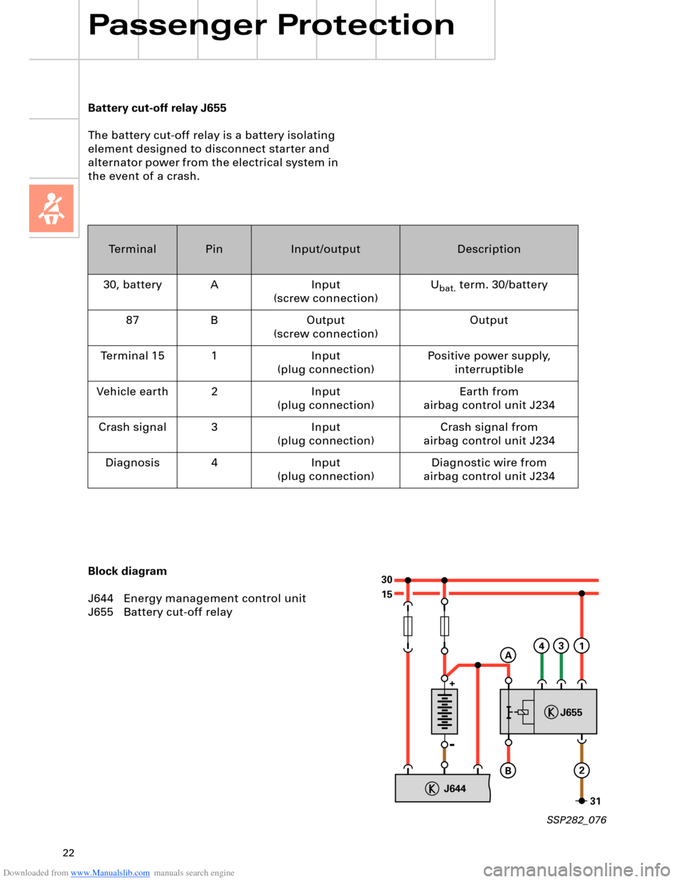
Battery cut-off relay J655
The battery cut-off relay is a battery isolating
element designed to disconnect starter and
alternator power from the electrical system in
the event of a crash.
Block diagram
J644 Energy management control unit
J655 Battery cut-off relay
SSP282_076
Page 24 of 96
Downloaded from www.Manualslib.com manuals search engine 24
Engine, Mechanics
200040006000
40
60
80
100
120
140
160
180
200
220
240
260
280 300
320
340 360380 400
420 440
460
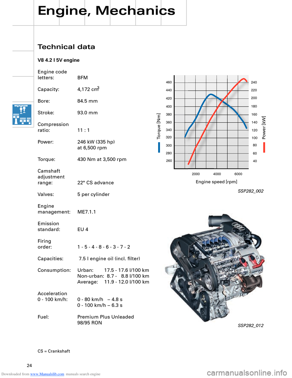
Technical data
V8 4.2 l 5V engine
Engine code
letters: BFM
Capacity:
3
Bore: 84.5 mm
Stroke: 93.0 mm
Compression
ratio: 11 : 1
Power: 246 kW (335 hp)
at 6,500 rpm
Torque: 430 Nm at 3,500 rpm
Camshaft
adjustment
range: 22° CS advance
Valves: 5 per cylinder
Engine
management: ME7.1.1
Emission
standard: EU 4
Firing
order: 1 - 5 - 4 - 8 - 6 - 3 - 7 - 2
Capacities: 7.5 l engine oil (incl. filter)
Consumption: Urban: 17.5 - 17.6 l/100 km Non-urban: 8.7 - 8.8 l/100 km
Average: 11.9 - 12.0 l/100 km
Acceleration
0 - 100 km/h: 0 - 80 km/h – 4.8 s 0 - 100 km/h – 6.3 s
Fuel: Premium Plus Unleaded 98/95 RON
CS = Crankshaft
SSP282_002
SSP282_012
Engine speed [rpm]
P
ower [kW]
T
orq ue [Nm]
4,172 cm
Page 25 of 96
Downloaded from www.Manualslib.com manuals search engine 25
200040006000
260
280 300
320
340 360380 400
420 440
46040
60
80
100
120
140
160
180
200
220
240
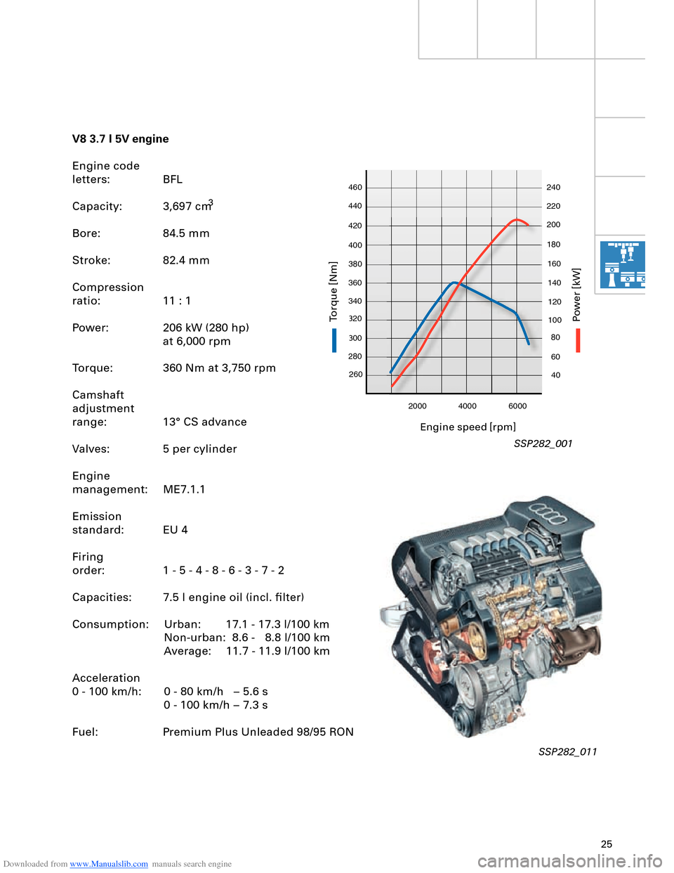
V8 3.7 l 5V engine
Engine code
letters: BFL
Capacity:
3
Bore: 84.5 mm
Stroke: 82.4 mm
Compression
ratio: 11 : 1
Power: 206 kW (280 hp)
at 6,000 rpm
Torque: 360 Nm at 3,750 rpm
Camshaft
adjustment
range: 13° CS advance
Valves: 5 per cylinder
Engine
management: ME7.1.1
Emission
standard: EU 4
Firing
order: 1 - 5 - 4 - 8 - 6 - 3 - 7 - 2
Capacities: 7.5 l engine oil (incl. filter)
Consumption: Urban: 17.1 - 17.3 l/100 km Non-urban: 8.6 - 8.8 l/100 km
Average: 11.7 - 11.9 l/100 km
Acceleration
0 - 100 km/h: 0 - 80 km/h – 5.6 s 0 - 100 km/h – 7.3 s
Fuel: Premium Plus Unleaded 98/95 RON
SSP282_001
SSP282_011
Engine speed [rpm]
P
ower [kW]
T
orq ue [Nm]
3,697 cm
Page 27 of 96
Downloaded from www.Manualslib.com manuals search engine 27
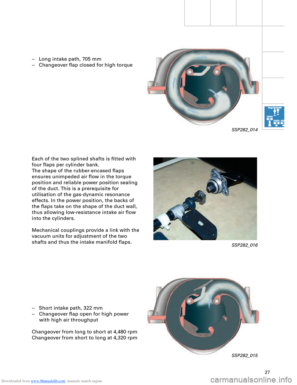
– Long intake path, 705 mm
– Changeover flap closed for high torque
Each of the two splined shafts is fitted with
four flaps per cylinder bank.
The shape of the rubber-encased flaps
ensures unimpeded air flow in the torque
position and reliable power position sealing
of the duct. This is a prerequisite for
utilisation of the gas-dynamic resonance
effects. In the power position, the backs of
the flaps take on the shape of the duct wall,
thus allowing low-resistance intake air flow
into the cylinders.
Mechanical couplings provide a link with the
vacuum units for adjustment of the two
shafts and thus the intake manifold flaps.
– Short intake path, 322 mm
– Changeover flap open for high power
with high air throughput
Changeover from long to short at 4,480 rpm
Changeover from short to long at 4,320 rpm
SSP282_014
SSP282_016
SSP282_015
Page 30 of 96
Downloaded from www.Manualslib.com manuals search engine 30
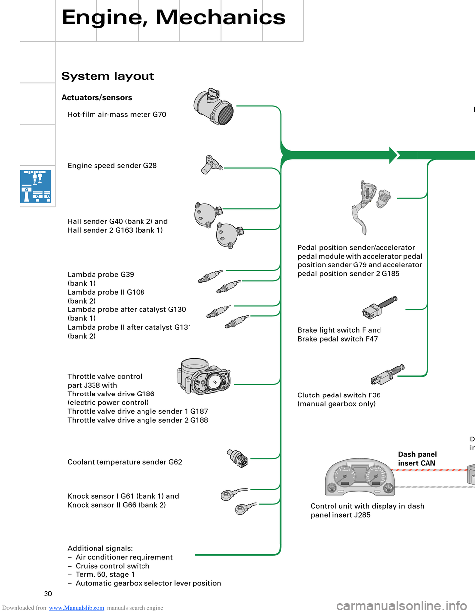
Hot-film air-mass meter G70
Engine speed sender G28
Hall sender G40 (bank 2) and
Hall sender 2 G163 (bank 1)
Lambda probe G39
(bank 1)
Lambda probe II G108
(bank 2)
Lambda probe after catalyst G130
(bank 1)
Lambda probe II after catalyst G131
(bank 2)
Throttle valve control
part J338 with
Throttle valve drive G186
(electric power control)
Throttle valve drive angle sender 1 G187
Throttle valve drive angle sender 2 G188
Coolant temperature sender G62
Knock sensor I G61 (bank 1) and
Knock sensor II G66 (bank 2)
Additional signals:
– Air conditioner requirement
– Cruise control switch
– Term. 50, stage 1
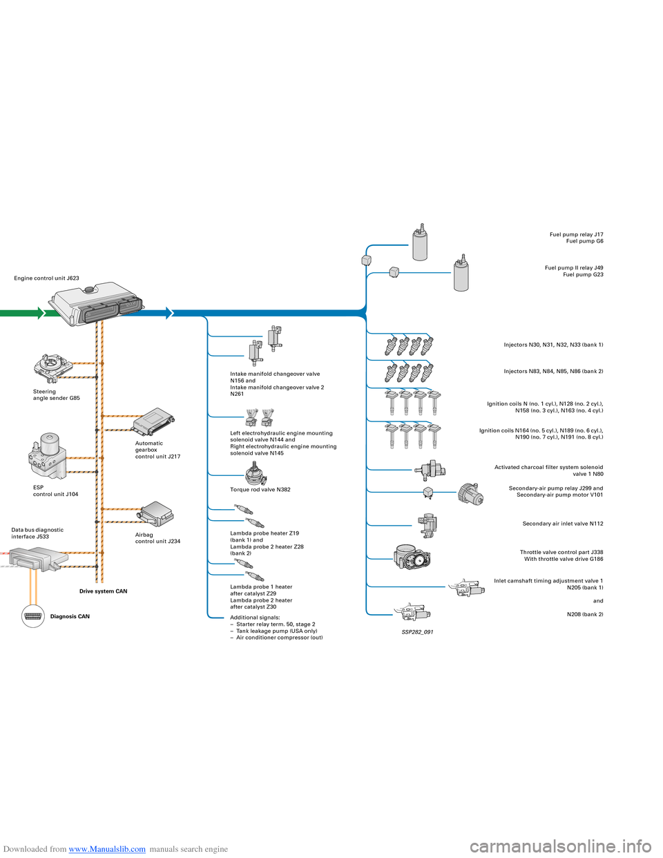
– Automatic gearbox selector lever positionEngine control unit J623
Steering
angle sender G85
ESP
control unit J104
Dash panel
insert CANAutomatic
gearbox
control unit J217
Airbag
control unit J234Intake manifold changeover valve
N156 and
Intake manifold changeover valve 2
N261
Left electrohydraulic engine mounting
solenoid valve N144 and
Right electrohydraulic engine mounting
solenoid valve N145
Torque rod valve N382
Lambda probe heater Z19
(bank 1) and
Lambda probe 2 heater Z28
(bank 2)
Lambda probe 1 heater
after catalyst Z29
Lambda probe 2 heater
after catalyst Z30
Additional signals:
– Starter relay term. 50, stage 2
– Tank leakage pump (USA only)
– Air conditioner compressor (out)Fuel pump relay J17
Fuel pump G6
Fuel pump II relay J49
Fuel pump G23
Injectors N30, N31, N32, N33 (bank 1)
Injectors N83, N84, N85, N86 (bank 2)
Ignition coils N (no. 1 cyl.), N128 (no. 2 cyl.),
N158 (no. 3 cyl.), N163 (no. 4 cyl.)
Ignition coils N164 (no. 5 cyl.), N189 (no. 6 cyl.),
N190 (no. 7 cyl.), N191 (no. 8 cyl.)
Activated charcoal filter system solenoid
valve 1 N80
Secondary-air pump relay J299 and
Secondary-air pump motor V101
Secondary air inlet valve N112
Throttle valve control part J338
With throttle valve drive G186
Inlet camshaft timing adjustment valve 1
N205 (bank 1)
and
N208 (bank 2) Pedal position sender/accelerator
pedal module with accelerator pedal
position sender G79 and accelerator
pedal position sender 2 G185
Brake light switch F and
Brake pedal switch F47
Clutch pedal switch F36
(manual gearbox only)
Control unit with display in dash
panel insert J285Data bus diagnostic
interface J533
Engine, Mechanics
System layout
Actuators/sensors
SSP282_091 Drive system CAN
Diagnosis CAN
Page 31 of 96
Downloaded from www.Manualslib.com manuals search engine 30
Hot-film air-mass meter G70
Engine speed sender G28
Hall sender G40 (bank 2) and
Hall sender 2 G163 (bank 1)
Lambda probe G39
(bank 1)
Lambda probe II G108
(bank 2)
Lambda probe after catalyst G130
(bank 1)
Lambda probe II after catalyst G131
(bank 2)
Throttle valve control
part J338 with
Throttle valve drive G186
(electric power control)
Throttle valve drive angle sender 1 G187
Throttle valve drive angle sender 2 G188
Coolant temperature sender G62
Knock sensor I G61 (bank 1) and
Knock sensor II G66 (bank 2)
Additional signals:
– Air conditioner requirement
– Cruise control switch
– Term. 50, stage 1
– Automatic gearbox selector lever positionEngine control unit J623
Steering
angle sender G85
ESP
control unit J104
Dash panel
insert CANAutomatic
gearbox
control unit J217
Airbag
control unit J234Intake manifold changeover valve
N156 and
Intake manifold changeover valve 2
N261
Left electrohydraulic engine mounting
solenoid valve N144 and
Right electrohydraulic engine mounting
solenoid valve N145
Torque rod valve N382
Lambda probe heater Z19
(bank 1) and
Lambda probe 2 heater Z28
(bank 2)
Lambda probe 1 heater
after catalyst Z29
Lambda probe 2 heater
after catalyst Z30
Additional signals:
– Starter relay term. 50, stage 2
– Tank leakage pump (USA only)
– Air conditioner compressor (out)Fuel pump relay J17
Fuel pump G6
Fuel pump II relay J49
Fuel pump G23
Injectors N30, N31, N32, N33 (bank 1)
Injectors N83, N84, N85, N86 (bank 2)
Ignition coils N (no. 1 cyl.), N128 (no. 2 cyl.),
N158 (no. 3 cyl.), N163 (no. 4 cyl.)
Ignition coils N164 (no. 5 cyl.), N189 (no. 6 cyl.),
N190 (no. 7 cyl.), N191 (no. 8 cyl.)
Activated charcoal filter system solenoid
valve 1 N80
Secondary-air pump relay J299 and
Secondary-air pump motor V101
Secondary air inlet valve N112
Throttle valve control part J338
With throttle valve drive G186
Inlet camshaft timing adjustment valve 1
N205 (bank 1)
and
N208 (bank 2) Pedal position sender/accelerator
pedal module with accelerator pedal
position sender G79 and accelerator
pedal position sender 2 G185
Brake light switch F and
Brake pedal switch F47
Clutch pedal switch F36
(manual gearbox only)
Control unit with display in dash
panel insert J285Data bus diagnostic
interface J533
Engine, Mechanics
System layout
Actuators/sensors
SSP282_091 Drive system CAN
Diagnosis CAN
Page 46 of 96
Downloaded from www.Manualslib.com manuals search engine 46
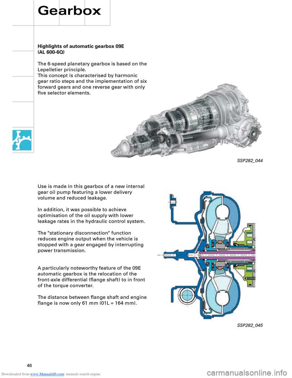
Highlights of automatic gearbox 09E
The 6-speed planetary gearbox is based on the
Lepelletier principle.
This concept is characterised by harmonic
gear ratio steps and the implementation of six
forward gears and one reverse gear with only
five selector elements.
Use is made in this gearbox of a new internal
gear oil pump featuring a lower delivery
volume and reduced leakage.
In addition, it was possible to achieve
optimisation of the oil supply with lower
leakage rates in the hydraulic control system.
The "stationary disconnection" function
reduces engine output when the vehicle is
stopped with a gear engaged by interrupting
power transmission.
A particularly noteworthy feature of the 09E
automatic gearbox is the relocation of the
front-axle differential (flange shaft) to in front
of the torque converter.
The distance between flange shaft and engine
flange is now only 61 mm (01L = 164 mm).
Gearbox
SSP282_044
SSP282_045
(AL 600-6Q)
Page 48 of 96
Downloaded from www.Manualslib.com manuals search engine 48
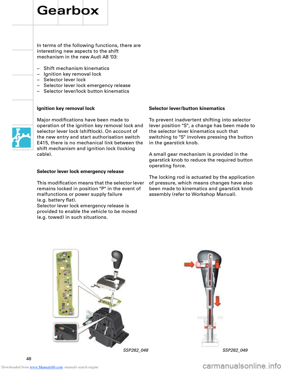
Selector lever/button kinematics
To prevent inadvertent shifting into selector
lever position "S", a change has been made to
the selector lever kinematics such that
switching to "S" involves pressing the button
in the gearstick knob.
A small gear mechanism is provided in the
gearstick knob to reduce the required button
operating force.
The locking rod is actuated by the application
of pressure, which means changes have also
been made to kinematics and gearstick knob
assembly (refer to Workshop Manual).
In terms of the following functions, there are
interesting new aspects to the shift
mechanism in the new Audi A8 '03:
– Shift mechanism kinematics
– Ignition key removal lock
– Selector lever lock
– Selector lever lock emergency release
– Selector lever/lock button kinematics
Ignition key removal lock
Major modifications have been made to
operation of the ignition key removal lock and
selector lever lock (shiftlock). On account of
the new entry and start authorisation switch
E415, there is no mechanical link between the
shift mechanism and ignition lock (locking
cable).
Selector lever lock emergency release
This modification means that the selector lever
remains locked in position "P" in the event of
malfunctions or power supply failure
(e.g. battery flat).
Selector lever lock emergency release is
provided to enable the vehicle to be moved
(e.g. towed) in such situations.
Gearbox
SSP282_048 SSP282_049
Page 54 of 96
Downloaded from www.Manualslib.com manuals search engine 54
Driver convenience is further enhanced, as
fewer accelerator and brake pedal operations
are required. Speed restrictions and safety
factors are reliably observed and the flow of
traffic thus better regulated.
ACC (Adaptive Cruise
Control)
Adaptive Cruise Control is a new system
designed to assist drivers and offers a much
wider range of functions than the
conventional Tempomat.
Running Gear
If the distance is less than desired, the vehicle is
decelerated by reducing power, changing gear
and if necessary applying the brakes.
In the interests of comfort, maximum possible
braking is restricted to approx. 25 % of the
maximum deceleration potential of the brake
system (full braking).
The control action is designed to assist the
driver and thus contributes to greater road
safety.
In certain traffic situations, active braking by the
driver may still be necessary. Summary of Adaptive Cruise Control (ACC)
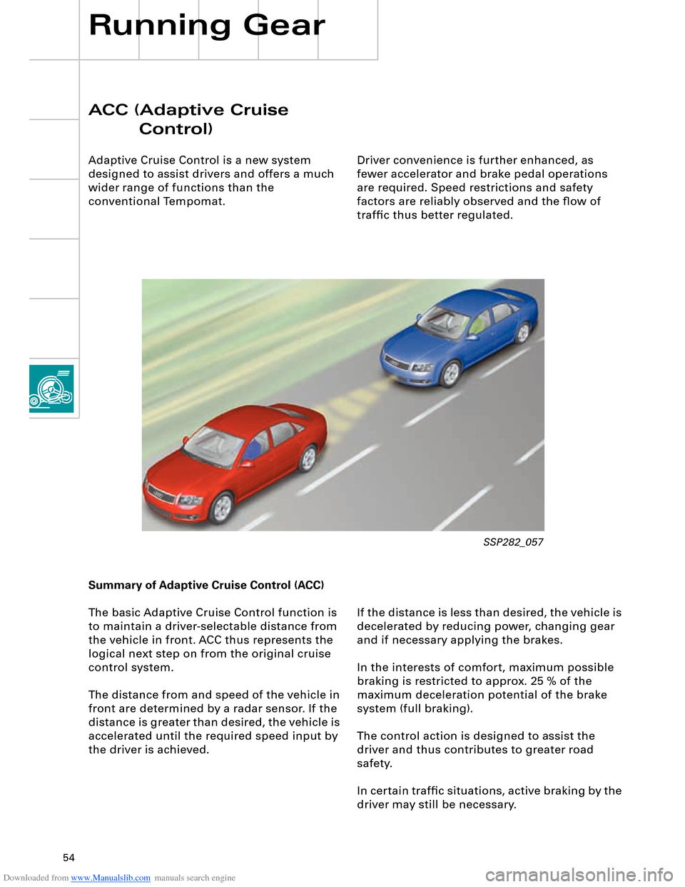
The basic Adaptive Cruise Control function is
to maintain a driver-selectable distance from
the vehicle in front. ACC thus represents the
logical next step on from the original cruise
control system.
The distance from and speed of the vehicle in
front are determined by a radar sensor. If the
distance is greater than desired, the vehicle is
accelerated until the required speed input by
the driver is achieved.
SSP282_057
Page 58 of 96
Downloaded from www.Manualslib.com manuals search engine 58
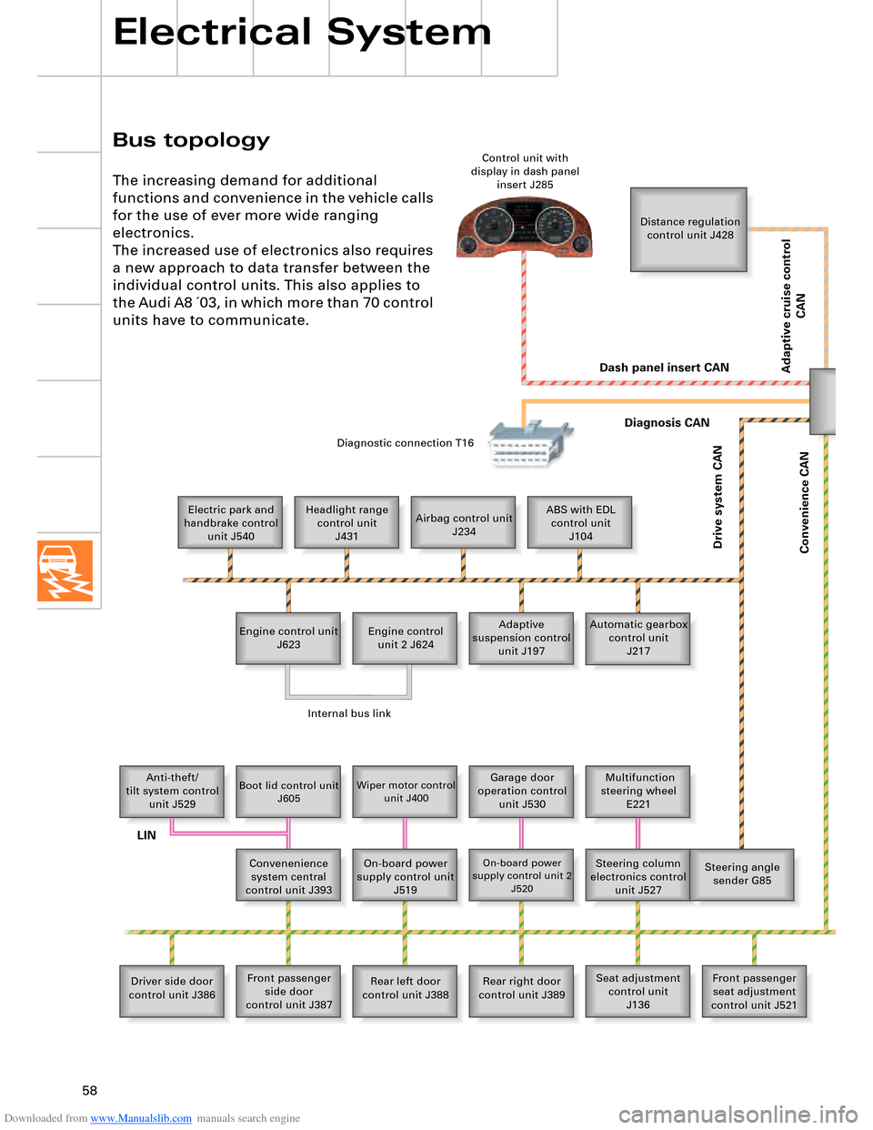
Bus topology
Electrical System
The increasing demand for additional
functions and convenience in the vehicle calls
for the use of ever more wide ranging
electronics.
The increased use of electronics also requires
a new approach to data transfer between the
individual control units. This also applies to
the Audi A8 ´03, in which more than 70 control
units have to communicate.
Distance regulation
control unit J428
Electric park and
handbrake control
unit J540Headlight range
control unit
J431Airbag control unit
J234ABS with EDL
control unit
J104
Engine control unit
J623Adaptive
suspension control
unit J197 Engine control
unit 2 J624Automatic gearbox
control unit
J217
Anti-theft/
tilt system control
unit J529
Boot lid control unit
J605Wiper motor control
unit J400Garage door
operation control
unit J530 Multifunction
steering wheel
E221
Convenenience
system central
control unit J393On-board power
supply control unit
J519
On-board power
supply control unit 2
J520Steering column
electronics control
unit J527Steering angle
sender G85
Driver side door
control unit J386Front passenger
side door
control unit J387Rear left door
control unit J388Rear right door
control unit J389Seat adjustment
control unit
J136Front passenger
seat adjustment
control unit J521 Control unit with
display in dash panel
insert J285
Diagnostic connection T16
Dash panel insert CAN
Drive system CAN
Diagnosis CAN
Convenience CAN
Internal bus link
LIN
Adaptive cruise control
CAN