Rear AUDI A8 2003 D3 / 2.G Technical Features Manual
[x] Cancel search | Manufacturer: AUDI, Model Year: 2003, Model line: A8, Model: AUDI A8 2003 D3 / 2.GPages: 96, PDF Size: 5.51 MB
Page 3 of 96
Downloaded from www.Manualslib.com manuals search engine 3
Attention
NoteNew
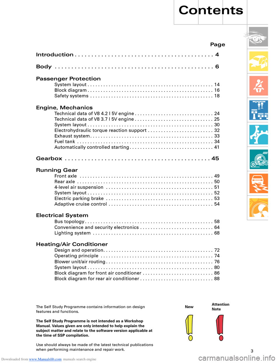
Contents
Page
Introduction . . . . . . . . . . . . . . . . . . . . . . . . . . . . . . . . . . . . . . . . . . 4
Body . . . . . . . . . . . . . . . . . . . . . . . . . . . . . . . . . . . . . . . . . . . . . . . . 6
Passenger Protection
System layout . . . . . . . . . . . . . . . . . . . . . . . . . . . . . . . . . . . . . . . . . . . . . . . . 14
Block diagram . . . . . . . . . . . . . . . . . . . . . . . . . . . . . . . . . . . . . . . . . . . . . . . . 16
Safety systems . . . . . . . . . . . . . . . . . . . . . . . . . . . . . . . . . . . . . . . . . . . . . . . 18
Engine, Mechanics
Technical data of V8 4.2 l 5V engine . . . . . . . . . . . . . . . . . . . . . . . . . . . . . . 24
Technical data of V8 3.7 l 5V engine . . . . . . . . . . . . . . . . . . . . . . . . . . . . . . 25
System layout . . . . . . . . . . . . . . . . . . . . . . . . . . . . . . . . . . . . . . . . . . . . . . . . 30
Electrohydraulic torque reaction support . . . . . . . . . . . . . . . . . . . . . . . . . 32
Exhaust system . . . . . . . . . . . . . . . . . . . . . . . . . . . . . . . . . . . . . . . . . . . . . . . 33
Fuel tank . . . . . . . . . . . . . . . . . . . . . . . . . . . . . . . . . . . . . . . . . . . . . . . . . . . . 34
Automatically controlled starting . . . . . . . . . . . . . . . . . . . . . . . . . . . . . . . . 41
Gearbox . . . . . . . . . . . . . . . . . . . . . . . . . . . . . . . . . . . . . . . . . . . . 45
Running Gear
Front axle . . . . . . . . . . . . . . . . . . . . . . . . . . . . . . . . . . . . . . . . . . . . . . . . . . . 49
Rear axle . . . . . . . . . . . . . . . . . . . . . . . . . . . . . . . . . . . . . . . . . . . . . . . . . . . . 50
4-level air suspension . . . . . . . . . . . . . . . . . . . . . . . . . . . . . . . . . . . . . . . . . 51
System layout . . . . . . . . . . . . . . . . . . . . . . . . . . . . . . . . . . . . . . . . . . . . . . . . 52
Electric parking brake . . . . . . . . . . . . . . . . . . . . . . . . . . . . . . . . . . . . . . . . . 53
Adaptive cruise control . . . . . . . . . . . . . . . . . . . . . . . . . . . . . . . . . . . . . . . . 54
Electrical System
Bus topology . . . . . . . . . . . . . . . . . . . . . . . . . . . . . . . . . . . . . . . . . . . . . . . . . 58
Convenience and security electronics . . . . . . . . . . . . . . . . . . . . . . . . . . . . 64
Lighting system . . . . . . . . . . . . . . . . . . . . . . . . . . . . . . . . . . . . . . . . . . . . . . 68
Heating/Air Conditioner
Design and operation. . . . . . . . . . . . . . . . . . . . . . . . . . . . . . . . . . . . . . . . . . 72
Operating principle . . . . . . . . . . . . . . . . . . . . . . . . . . . . . . . . . . . . . . . . . . . 74
Blower unit/air routing . . . . . . . . . . . . . . . . . . . . . . . . . . . . . . . . . . . . . . . . . 76
System layout . . . . . . . . . . . . . . . . . . . . . . . . . . . . . . . . . . . . . . . . . . . . . . . . 80
Block diagram for front air conditioner . . . . . . . . . . . . . . . . . . . . . . . . . . . 86
Block diagram for rear air conditioner . . . . . . . . . . . . . . . . . . . . . . . . . . . . 88
The Self Study Programme contains information on design
features and functions.
The Self Study Programme is not intended as a Workshop
Manual. Values given are only intended to help explain the
subject matter and relate to the software version applicable at
the time of SSP compilation.
Use should always be made of the latest technical publications
when performing maintenance and repair work.
Page 9 of 96
Downloaded from www.Manualslib.com manuals search engine 9
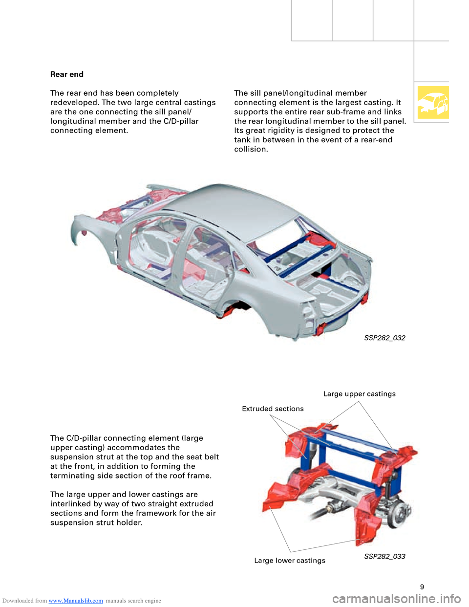
Rear end
The rear end has been completely
redeveloped. The two large central castings
are the one connecting the sill panel/
longitudinal member and the C/D-pillar
connecting element.
SSP282_032
The C/D-pillar connecting element (large
upper casting) accommodates the
suspension strut at the top and the seat belt
at the front, in addition to forming the
terminating side section of the roof frame.
The large upper and lower castings are
interlinked by way of two straight extruded
sections and form the framework for the air
suspension strut holder.
SSP282_033
The sill panel/longitudinal member
connecting element is the largest casting. It
supports the entire rear sub-frame and links
the rear longitudinal member to the sill panel.
Its great rigidity is designed to protect the
tank in between in the event of a rear-end
collision.
Large upper castings
Extruded sections
Large lower castings
Page 12 of 96
Downloaded from www.Manualslib.com manuals search engine 12
Body
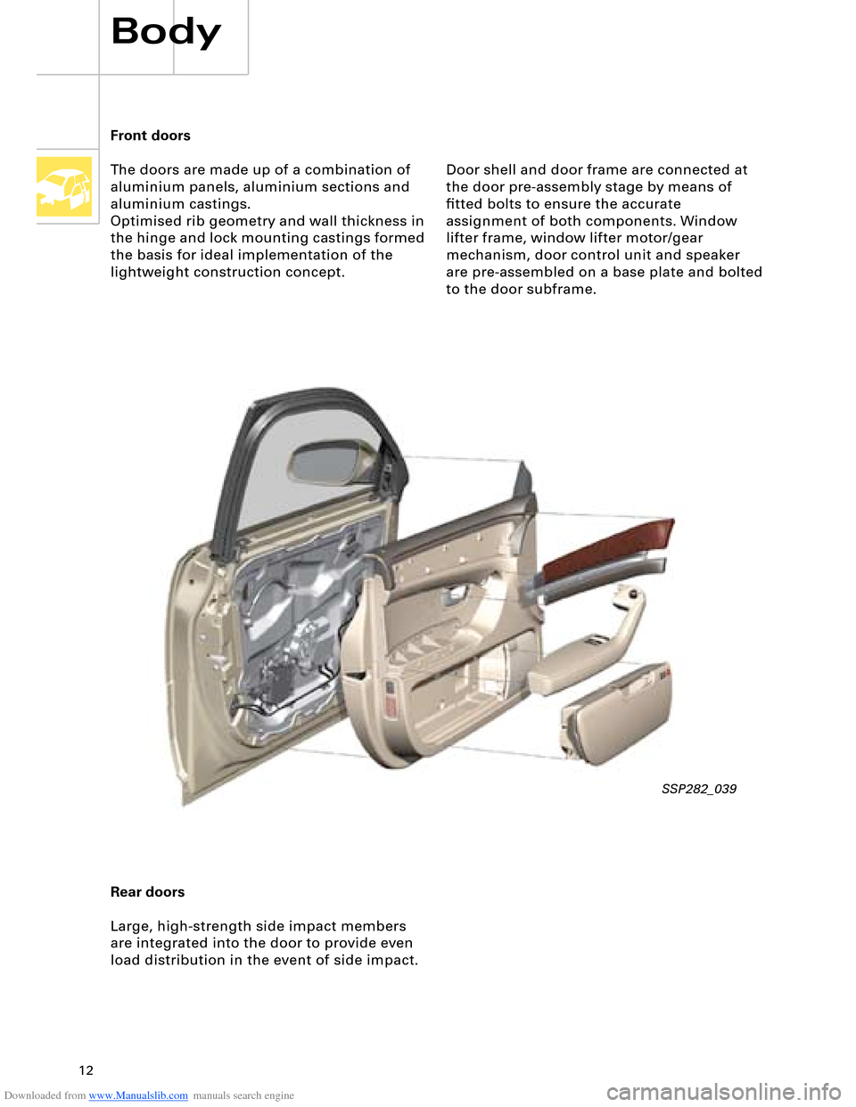
Front doors
The doors are made up of a combination of
aluminium panels, aluminium sections and
aluminium castings.
Optimised rib geometry and wall thickness in
the hinge and lock mounting castings formed
the basis for ideal implementation of the
lightweight construction concept.
Rear doors
Large, high-strength side impact members
are integrated into the door to provide even
load distribution in the event of side impact.
SSP282_039
Door shell and door frame are connected at
the door pre-assembly stage by means of
fitted bolts to ensure the accurate
assignment of both components. Window
lifter frame, window lifter motor/gear
mechanism, door control unit and speaker
are pre-assembled on a base plate and bolted
to the door subframe.
Page 13 of 96
Downloaded from www.Manualslib.com manuals search engine 13
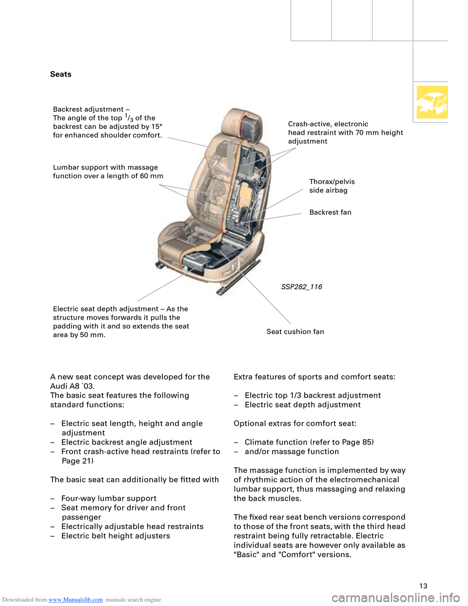
Seats
A new seat concept was developed for the
Audi A8 ´03.
The basic seat features the following
standard functions:
– Electric seat length, height and angle
adjustment
– Electric backrest angle adjustment
– Front crash-active head restraints (refer to
Page 21)
The basic seat can additionally be fitted with
– Four-way lumbar support
– Seat memory for driver and front
passenger
– Electrically adjustable head restraints
– Electric belt height adjustersExtra features of sports and comfort seats:
– Electric top 1/3 backrest adjustment
– Electric seat depth adjustment
Optional extras for comfort seat:
– Climate function (refer to Page 85)
– and/or massage function
The massage function is implemented by way
of rhythmic action of the electromechanical
lumbar support, thus massaging and relaxing
the back muscles.
The fixed rear seat bench versions correspond
to those of the front seats, with the third head
restraint being fully retractable. Electric
individual seats are however only available as
"Basic" and "Comfort" versions.
SSP282_116
Crash-active, electronic
head restraint with 70 mm height
adjustment
Thorax/pelvis
side airbag
Backrest fan
Seat cushion fan Electric seat depth adjustment – As the
structure moves forwards it pulls the
padding with it and so extends the seat
area by 50 mm. Backrest adjustment –
The angle of the top
1/3 of the
backrest can be adjusted by 15°
for enhanced shoulder comfort.
Lumbar support with massage
function over a length of 60 mm
Page 15 of 96
Downloaded from www.Manualslib.com manuals search engine 15
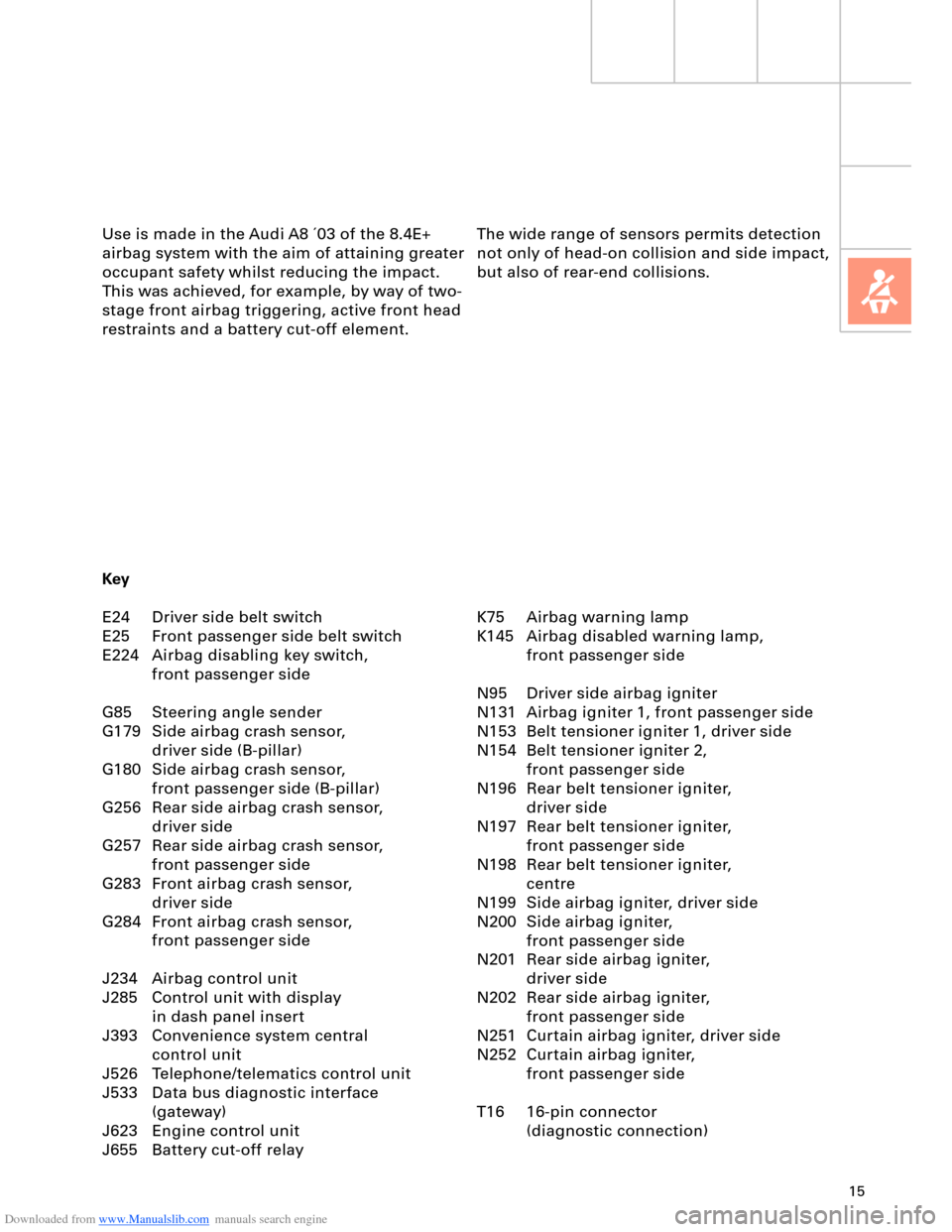
The wide range of sensors permits detection
not only of head-on collision and side impact,
but also of rear-end collisions. Use is made in the Audi A8 ´03 of the 8.4E+
airbag system with the aim of attaining greater
occupant safety whilst reducing the impact.
This was achieved, for example, by way of two-
stage front airbag triggering, active front head
restraints and a battery cut-off element.
K75 Airbag warning lamp
K145 Airbag disabled warning lamp,
front passenger side
N95 Driver side airbag igniter
N131 Airbag igniter 1, front passenger side
N153 Belt tensioner igniter 1, driver side
N154 Belt tensioner igniter 2,
front passenger side
N196 Rear belt tensioner igniter,
driver side
N197 Rear belt tensioner igniter,
front passenger side
N198 Rear belt tensioner igniter,
centre
N199 Side airbag igniter, driver side
N200 Side airbag igniter,
front passenger side
N201 Rear side airbag igniter,
driver side
N202 Rear side airbag igniter,
front passenger side
N251 Curtain airbag igniter, driver side
N252 Curtain airbag igniter,
front passenger side
T16 16-pin connector
(diagnostic connection) Key
E24 Driver side belt switch
E25 Front passenger side belt switch
E224 Airbag disabling key switch,
front passenger side
G85 Steering angle sender
G179 Side airbag crash sensor,
driver side (B-pillar)
G180 Side airbag crash sensor,
front passenger side (B-pillar)
G256 Rear side airbag crash sensor,
driver side
G257 Rear side airbag crash sensor,
front passenger side
G283 Front airbag crash sensor,
driver side
G284 Front airbag crash sensor,
front passenger side
J234 Airbag control unit
J285 Control unit with display
in dash panel insert
J393 Convenience system central
control unit
J526 Telephone/telematics control unit
J533 Data bus diagnostic interface
(gateway)
J623 Engine control unit
J655 Battery cut-off relay
Page 16 of 96
Downloaded from www.Manualslib.com manuals search engine 16
15
J234
J655
1
2
E224
3
G283G284G179
N131
F138
N202N199N200N201N95
Key
E24 Driver side belt switch
E25 Front passenger side belt switch
E224 Airbag disabling key switch,
front passenger side
F138 Airbag coil connector/return spring
with slip ring
G179 Side airbag crash sensor,
driver side
G180 Side airbag crash sensor,
front passenger side
G256 Rear side airbag crash sensor,
driver side
G257 Rear side airbag crash sensor,
front passenger side
G283 Front airbag crash sensor,
driver side
G284 Front airbag crash sensor,
front passenger side
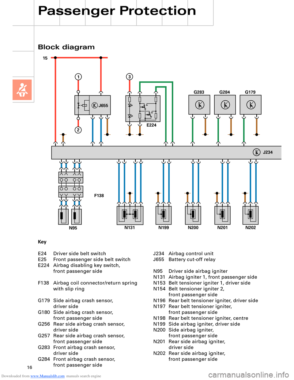
Block diagram
Passenger Protection
J234 Airbag control unit
J655 Battery cut-off relay
N95 Driver side airbag igniter
N131 Airbag igniter 1, front passenger side
N153 Belt tensioner igniter 1, driver side
N154 Belt tensioner igniter 2,
front passenger side
N196 Rear belt tensioner igniter, driver side
N197 Rear belt tensioner igniter,
front passenger side
N198 Rear belt tensioner igniter, centre
N199 Side airbag igniter, driver side
N200 Side airbag igniter,
front passenger side
N201 Rear side airbag igniter,
driver side
N202 Rear side airbag igniter,
front passenger side
Page 20 of 96
Downloaded from www.Manualslib.com manuals search engine 20
Passenger Protection
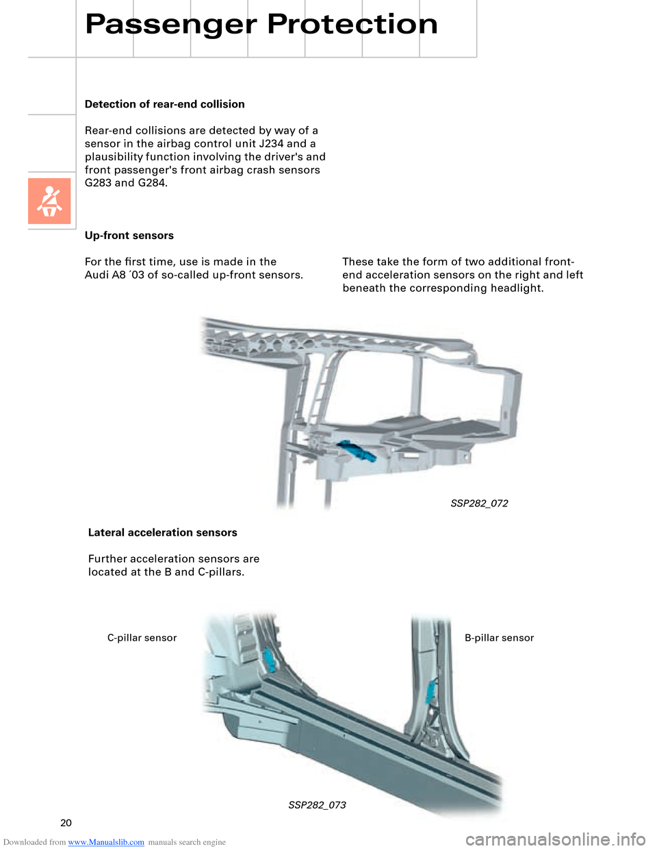
Up-front sensors
For the first time, use is made in the
Audi A8 ´03 of so-called up-front sensors.
SSP282_072
Lateral acceleration sensors
Further acceleration sensors are
located at the B and C-pillars.
SSP282_073
Detection of rear-end collision
Rear-end collisions are detected by way of a
sensor in the airbag control unit J234 and a
plausibility function involving the driver's and
front passenger's front airbag crash sensors
G283 and G284.
These take the form of two additional front-
end acceleration sensors on the right and left
beneath the corresponding headlight.
C-pillar sensor B-pillar sensor
Page 21 of 96
Downloaded from www.Manualslib.com manuals search engine 21
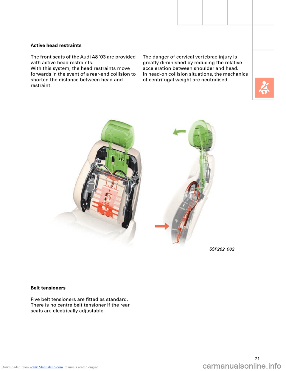
Active head restraints
The front seats of the Audi A8 ´03 are provided
with active head restraints.
With this system, the head restraints move
forwards in the event of a rear-end collision to
shorten the distance between head and
restraint.
SSP282_082
The danger of cervical vertebrae injury is
greatly diminished by reducing the relative
acceleration between shoulder and head.
In head-on collision situations, the mechanics
of centrifugal weight are neutralised.
Belt tensioners
Five belt tensioners are fitted as standard.
There is no centre belt tensioner if the rear
seats are electrically adjustable.
Page 33 of 96
Downloaded from www.Manualslib.com manuals search engine 33
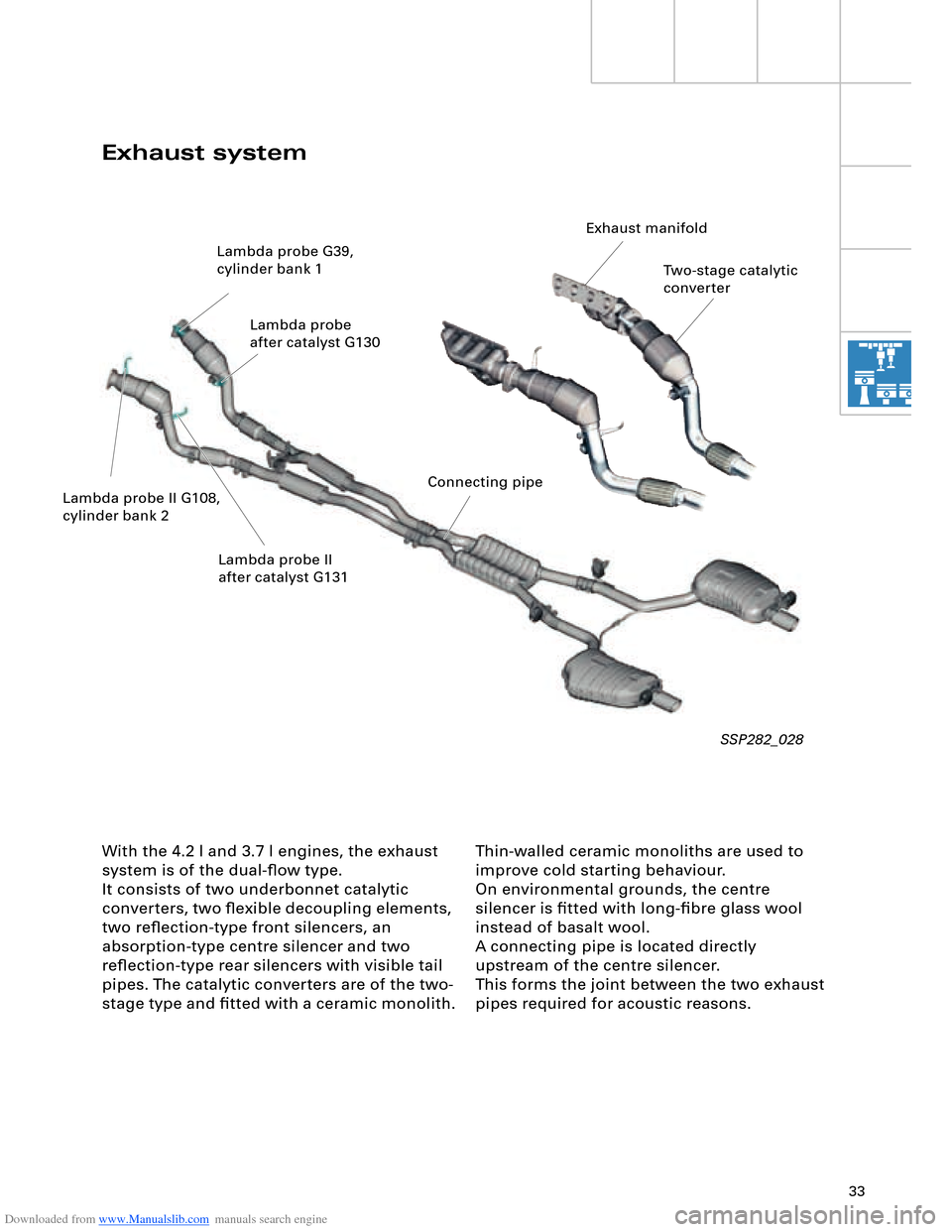
Thin-walled ceramic monoliths are used to
improve cold starting behaviour.
On environmental grounds, the centre
silencer is fitted with long-fibre glass wool
instead of basalt wool.
A connecting pipe is located directly
upstream of the centre silencer.
This forms the joint between the two exhaust
pipes required for acoustic reasons.
With the 4.2 l and 3.7 l engines, the exhaust
system is of the dual-flow type.
It consists of two underbonnet catalytic
converters, two flexible decoupling elements,
two reflection-type front silencers, an
absorption-type centre silencer and two
reflection-type rear silencers with visible tail
pipes. The catalytic converters are of the two-
stage type and fitted with a ceramic monolith.
SSP282_028
Exhaust system
Two-stage catalytic
converter
Lambda probe G39,
cylinder bank 1
Lambda probe
after catalyst G130
Lambda probe II G108,
cylinder bank 2 Lambda probe II
after catalyst G131 Exhaust manifold
Connecting pipe
Page 34 of 96
Downloaded from www.Manualslib.com manuals search engine 34
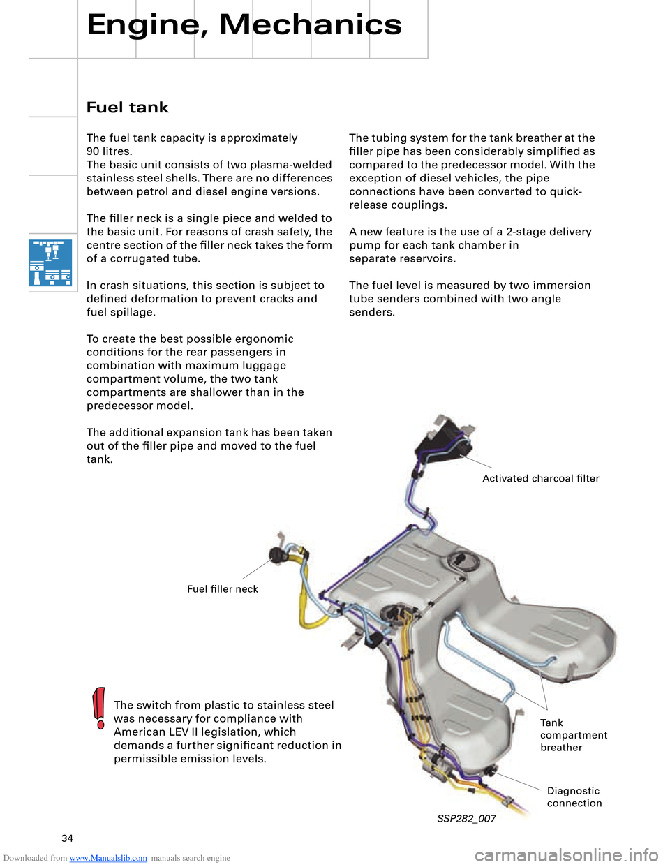
The tubing system for the tank breather at the
filler pipe has been considerably simplified as
compared to the predecessor model. With the
exception of diesel vehicles, the pipe
connections have been converted to quick-
release couplings.
A new feature is the use of a 2-stage delivery
pump for each tank chamber in
separate reservoirs.
The fuel level is measured by two immersion
tube senders combined with two angle
senders.
Engine, Mechanics
SSP282_007
Fuel tank
The fuel tank capacity is approximately
90 litres.
The basic unit consists of two plasma-welded
stainless steel shells. There are no differences
between petrol and diesel engine versions.
The filler neck is a single piece and welded to
the basic unit. For reasons of crash safety, the
centre section of the filler neck takes the form
of a corrugated tube.
In crash situations, this section is subject to
defined deformation to prevent cracks and
fuel spillage.
To create the best possible ergonomic
conditions for the rear passengers in
combination with maximum luggage
compartment volume, the two tank
compartments are shallower than in the
predecessor model.
The additional expansion tank has been taken
out of the filler pipe and moved to the fuel
tank.
The switch from plastic to stainless steel
was necessary for compliance with
American LEV II legislation, which
demands a further significant reduction in
permissible emission levels.
Activated charcoal filter
Fuel filler neck
Tank
compartment
breather
Diagnostic
connection