Suspension AUDI A8 2003 D3 / 2.G Technical Features Manual
[x] Cancel search | Manufacturer: AUDI, Model Year: 2003, Model line: A8, Model: AUDI A8 2003 D3 / 2.GPages: 96, PDF Size: 5.51 MB
Page 2 of 96
Downloaded from www.Manualslib.com manuals search engine Complete vehicle information
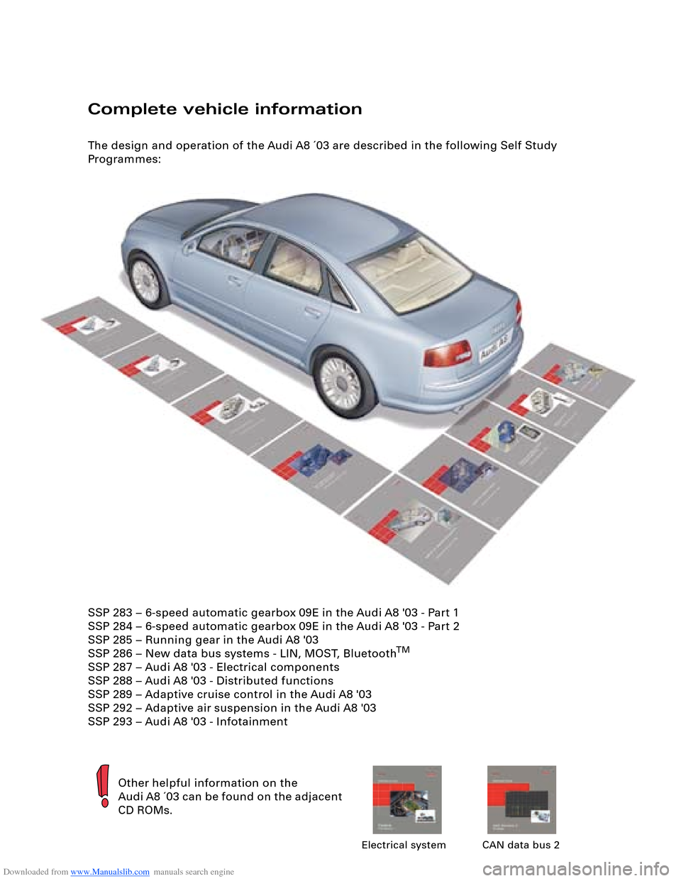
The design and operation of the Audi A8 ´03 are described in the following Self Study
Programmes:
Other helpful information on the
Audi A8 ´03 can be found on the adjacent
CD ROMs.
Electrical system CAN data bus 2
SSP 283 – 6-speed automatic gearbox 09E in the Audi A8 '03 - Part 1
SSP 284 – 6-speed automatic gearbox 09E in the Audi A8 '03 - Part 2
SSP 285 – Running gear in the Audi A8 '03
SSP 286 – New data bus systems - LIN, MOST, Bluetooth
TM
SSP 287 – Audi A8 '03 - Electrical components
SSP 288 – Audi A8 '03 - Distributed functions
SSP 289 – Adaptive cruise control in the Audi A8 '03
SSP 292 – Adaptive air suspension in the Audi A8 '03
SSP 293 – Audi A8 '03 - Infotainment
Page 3 of 96
Downloaded from www.Manualslib.com manuals search engine 3
Attention
NoteNew
Contents
Page
Introduction . . . . . . . . . . . . . . . . . . . . . . . . . . . . . . . . . . . . . . . . . . 4
Body . . . . . . . . . . . . . . . . . . . . . . . . . . . . . . . . . . . . . . . . . . . . . . . . 6
Passenger Protection
System layout . . . . . . . . . . . . . . . . . . . . . . . . . . . . . . . . . . . . . . . . . . . . . . . . 14
Block diagram . . . . . . . . . . . . . . . . . . . . . . . . . . . . . . . . . . . . . . . . . . . . . . . . 16
Safety systems . . . . . . . . . . . . . . . . . . . . . . . . . . . . . . . . . . . . . . . . . . . . . . . 18
Engine, Mechanics
Technical data of V8 4.2 l 5V engine . . . . . . . . . . . . . . . . . . . . . . . . . . . . . . 24
Technical data of V8 3.7 l 5V engine . . . . . . . . . . . . . . . . . . . . . . . . . . . . . . 25
System layout . . . . . . . . . . . . . . . . . . . . . . . . . . . . . . . . . . . . . . . . . . . . . . . . 30
Electrohydraulic torque reaction support . . . . . . . . . . . . . . . . . . . . . . . . . 32
Exhaust system . . . . . . . . . . . . . . . . . . . . . . . . . . . . . . . . . . . . . . . . . . . . . . . 33
Fuel tank . . . . . . . . . . . . . . . . . . . . . . . . . . . . . . . . . . . . . . . . . . . . . . . . . . . . 34
Automatically controlled starting . . . . . . . . . . . . . . . . . . . . . . . . . . . . . . . . 41
Gearbox . . . . . . . . . . . . . . . . . . . . . . . . . . . . . . . . . . . . . . . . . . . . 45
Running Gear
Front axle . . . . . . . . . . . . . . . . . . . . . . . . . . . . . . . . . . . . . . . . . . . . . . . . . . . 49
Rear axle . . . . . . . . . . . . . . . . . . . . . . . . . . . . . . . . . . . . . . . . . . . . . . . . . . . . 50
4-level air suspension . . . . . . . . . . . . . . . . . . . . . . . . . . . . . . . . . . . . . . . . . 51
System layout . . . . . . . . . . . . . . . . . . . . . . . . . . . . . . . . . . . . . . . . . . . . . . . . 52
Electric parking brake . . . . . . . . . . . . . . . . . . . . . . . . . . . . . . . . . . . . . . . . . 53
Adaptive cruise control . . . . . . . . . . . . . . . . . . . . . . . . . . . . . . . . . . . . . . . . 54
Electrical System
Bus topology . . . . . . . . . . . . . . . . . . . . . . . . . . . . . . . . . . . . . . . . . . . . . . . . . 58
Convenience and security electronics . . . . . . . . . . . . . . . . . . . . . . . . . . . . 64
Lighting system . . . . . . . . . . . . . . . . . . . . . . . . . . . . . . . . . . . . . . . . . . . . . . 68
Heating/Air Conditioner
Design and operation. . . . . . . . . . . . . . . . . . . . . . . . . . . . . . . . . . . . . . . . . . 72
Operating principle . . . . . . . . . . . . . . . . . . . . . . . . . . . . . . . . . . . . . . . . . . . 74
Blower unit/air routing . . . . . . . . . . . . . . . . . . . . . . . . . . . . . . . . . . . . . . . . . 76
System layout . . . . . . . . . . . . . . . . . . . . . . . . . . . . . . . . . . . . . . . . . . . . . . . . 80
Block diagram for front air conditioner . . . . . . . . . . . . . . . . . . . . . . . . . . . 86
Block diagram for rear air conditioner . . . . . . . . . . . . . . . . . . . . . . . . . . . . 88
The Self Study Programme contains information on design
features and functions.
The Self Study Programme is not intended as a Workshop
Manual. Values given are only intended to help explain the
subject matter and relate to the software version applicable at
the time of SSP compilation.
Use should always be made of the latest technical publications
when performing maintenance and repair work.
Page 5 of 96
Downloaded from www.Manualslib.com manuals search engine 5
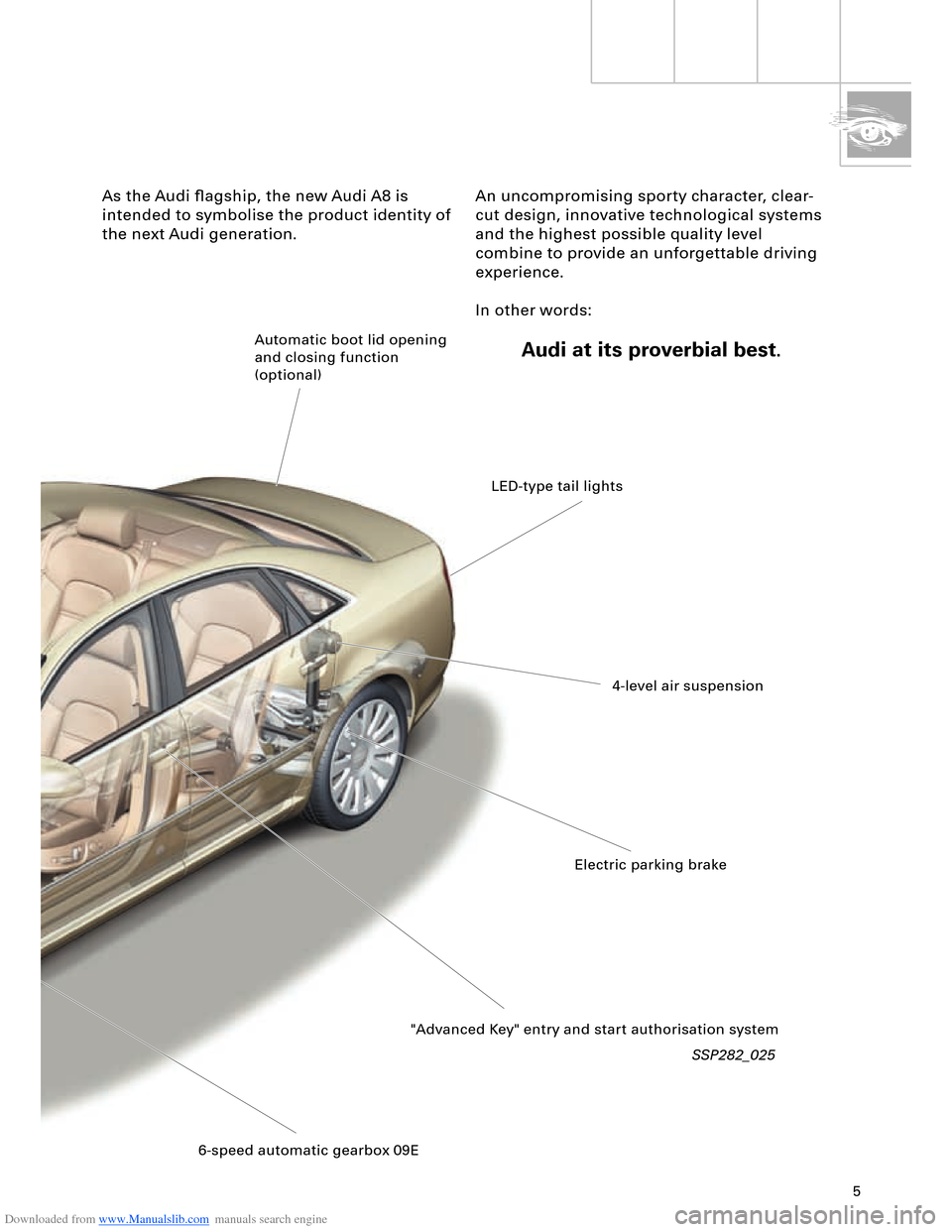
SSP282_025
As the Audi flagship, the new Audi A8 is
intended to symbolise the product identity of
the next Audi generation.An uncompromising sporty character, clear-
cut design, innovative technological systems
and the highest possible quality level
combine to provide an unforgettable driving
experience.
In other words:
Audi at its proverbial best.Automatic boot lid opening
and closing function
(optional)
LED-type tail lights
4-level air suspension
Electric parking brake
"Advanced Key" entry and start authorisation system
6-speed automatic gearbox 09E
Page 9 of 96
Downloaded from www.Manualslib.com manuals search engine 9
Rear end
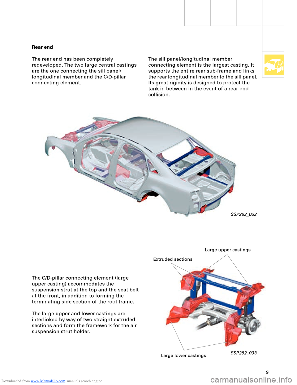
The rear end has been completely
redeveloped. The two large central castings
are the one connecting the sill panel/
longitudinal member and the C/D-pillar
connecting element.
SSP282_032
The C/D-pillar connecting element (large
upper casting) accommodates the
suspension strut at the top and the seat belt
at the front, in addition to forming the
terminating side section of the roof frame.
The large upper and lower castings are
interlinked by way of two straight extruded
sections and form the framework for the air
suspension strut holder.
SSP282_033
The sill panel/longitudinal member
connecting element is the largest casting. It
supports the entire rear sub-frame and links
the rear longitudinal member to the sill panel.
Its great rigidity is designed to protect the
tank in between in the event of a rear-end
collision.
Large upper castings
Extruded sections
Large lower castings
Page 49 of 96
Downloaded from www.Manualslib.com manuals search engine 49
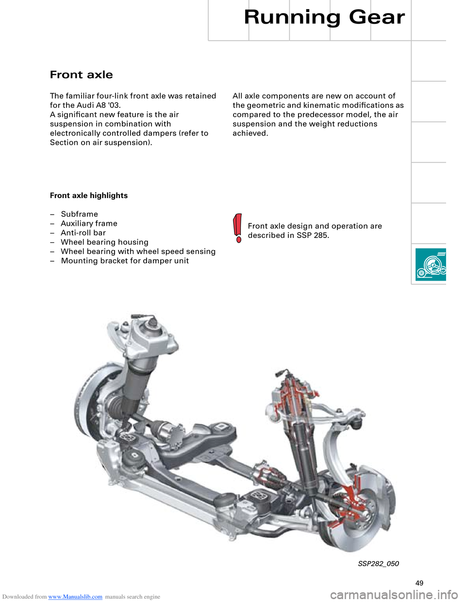
All axle components are new on account of
the geometric and kinematic modifications as
compared to the predecessor model, the air
suspension and the weight reductions
achieved.
Front axle
The familiar four-link front axle was retained
for the Audi A8 '03.
A significant new feature is the air
suspension in combination with
electronically controlled dampers (refer to
Section on air suspension).
Front axle highlights
– Subframe
– Auxiliary frame
– Anti-roll bar
– Wheel bearing housing
– Wheel bearing with wheel speed sensing
– Mounting bracket for damper unit
Front axle design and operation are
described in SSP 285.
SSP282_050
Running Gear
Page 50 of 96
Downloaded from www.Manualslib.com manuals search engine 50
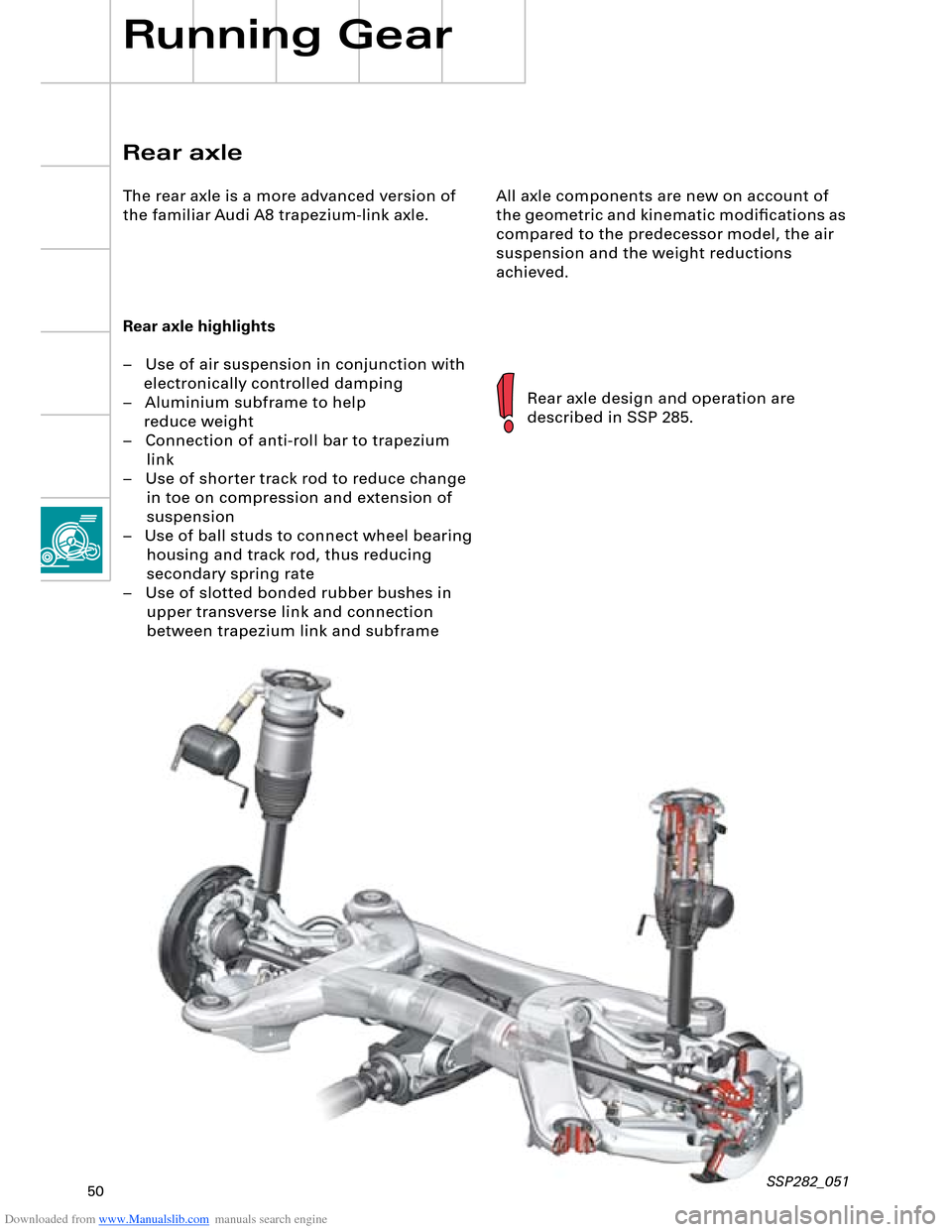
All axle components are new on account of
the geometric and kinematic modifications as
compared to the predecessor model, the air
suspension and the weight reductions
achieved.
Rear axle highlights
– Use of air suspension in conjunction with
electronically controlled damping
– Aluminium subframe to help
reduce weight
– Connection of anti-roll bar to trapezium
link
– Use of shorter track rod to reduce change
in toe on compression and extension of
suspension
– Use of ball studs to connect wheel bearing
housing and track rod, thus reducing
secondary spring rate
– Use of slotted bonded rubber bushes in
upper transverse link and connection
between trapezium link and subframe
Rear axle design and operation are
described in SSP 285.
Rear axle
The rear axle is a more advanced version of
the familiar Audi A8 trapezium-link axle.
Running Gear
SSP282_051
Page 51 of 96
Downloaded from www.Manualslib.com manuals search engine 51
4-level air suspension
The introduction of the Audi A8 ´03 is
accompanied by a system featuring new
technical details and functions. The major
differences with respect to the familiar Audi
allroad quattro
® system are as follows:
EDC instead of PDC damping
The control system makes allowance for the
currently applicable driving status. Wheel
movement (unsprung masses) and body
movement (sprung masses) are detected.
Various damping characteristic curves are
implemented within the scope of three
selectable programs (modes) and each
damper can be controlled individually.
Control concept
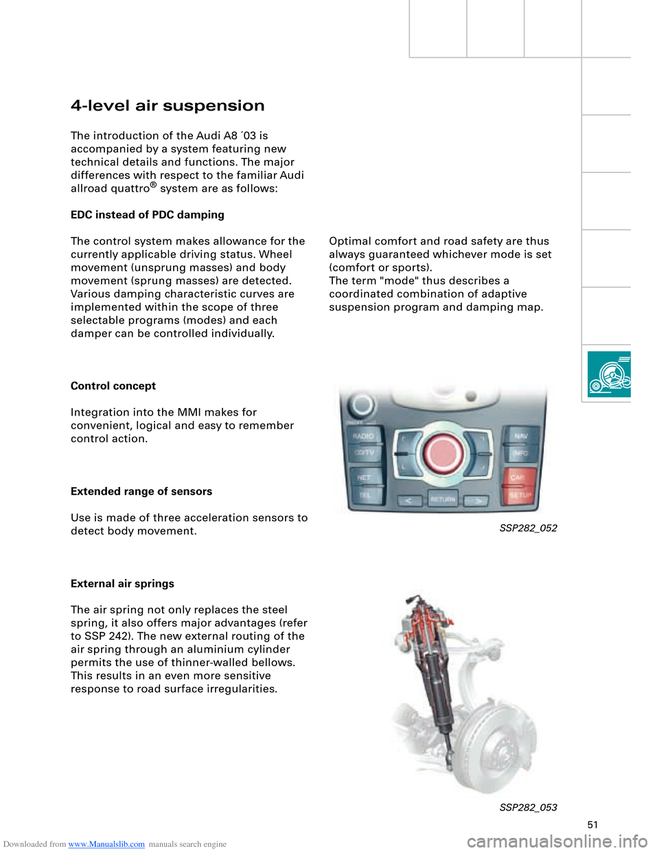
Integration into the MMI makes for
convenient, logical and easy to remember
control action.
Extended range of sensors
Use is made of three acceleration sensors to
detect body movement.
External air springs
The air spring not only replaces the steel
spring, it also offers major advantages (refer
to SSP 242). The new external routing of the
air spring through an aluminium cylinder
permits the use of thinner-walled bellows.
This results in an even more sensitive
response to road surface irregularities.
SSP282_052
SSP282_053
Optimal comfort and road safety are thus
always guaranteed whichever mode is set
(comfort or sports).
The term "mode" thus describes a
coordinated combination of adaptive
suspension program and damping map.
Page 52 of 96
Downloaded from www.Manualslib.com manuals search engine 52
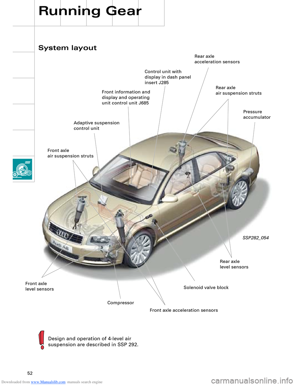
System layout
Running Gear
SSP282_054
Design and operation of 4-level air
suspension are described in SSP 292.
Front information and
display and operating
unit control unit J685
Front axle
level sensorsSolenoid valve blockRear axle
level sensorsPressure
accumulator
Adaptive suspension
control unitRear axle
air suspension struts Rear axle
acceleration sensors
CompressorControl unit with
display in dash panel
insert J285
Front axle
air suspension struts
Front axle acceleration sensors
Page 58 of 96
Downloaded from www.Manualslib.com manuals search engine 58
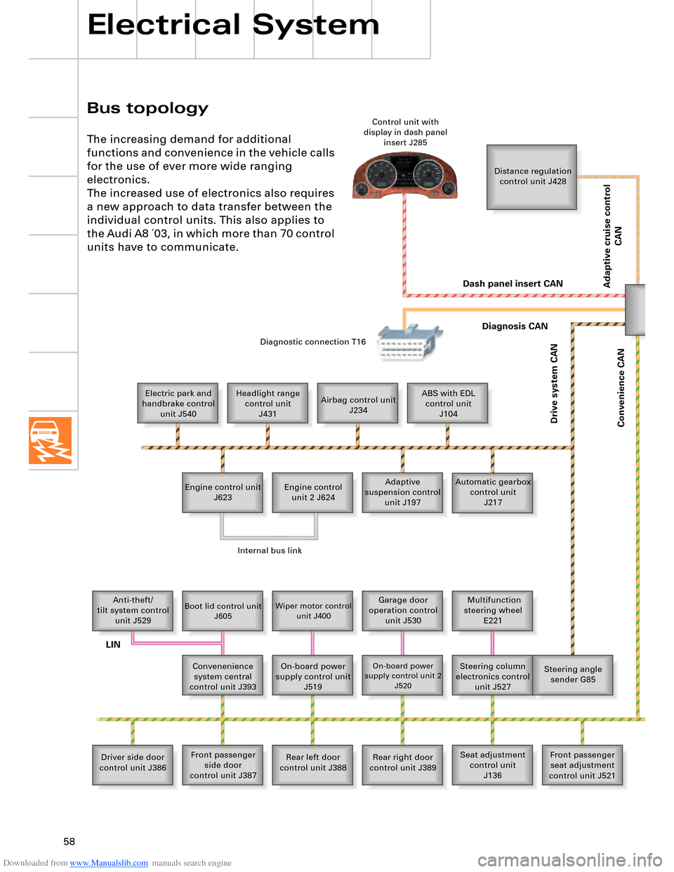
Bus topology
Electrical System
The increasing demand for additional
functions and convenience in the vehicle calls
for the use of ever more wide ranging
electronics.
The increased use of electronics also requires
a new approach to data transfer between the
individual control units. This also applies to
the Audi A8 ´03, in which more than 70 control
units have to communicate.
Distance regulation
control unit J428
Electric park and
handbrake control
unit J540Headlight range
control unit
J431Airbag control unit
J234ABS with EDL
control unit
J104
Engine control unit
J623Adaptive
suspension control
unit J197 Engine control
unit 2 J624Automatic gearbox
control unit
J217
Anti-theft/
tilt system control
unit J529
Boot lid control unit
J605Wiper motor control
unit J400Garage door
operation control
unit J530 Multifunction
steering wheel
E221
Convenenience
system central
control unit J393On-board power
supply control unit
J519
On-board power
supply control unit 2
J520Steering column
electronics control
unit J527Steering angle
sender G85
Driver side door
control unit J386Front passenger
side door
control unit J387Rear left door
control unit J388Rear right door
control unit J389Seat adjustment
control unit
J136Front passenger
seat adjustment
control unit J521 Control unit with
display in dash panel
insert J285
Diagnostic connection T16
Dash panel insert CAN
Drive system CAN
Diagnosis CAN
Convenience CAN
Internal bus link
LIN
Adaptive cruise control
CAN
Page 68 of 96
Downloaded from www.Manualslib.com manuals search engine 68
Electrical System
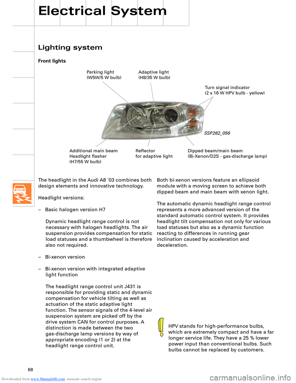
The headlight in the Audi A8 ´03 combines both
design elements and innovative technology.
Headlight versions:
– Basic halogen version H7
Dynamic headlight range control is not
necessary with halogen headlights. The air
suspension provides compensation for static
load statuses and a thumbwheel is therefore
also not required.
– Bi-xenon version
– Bi-xenon version with integrated adaptive
light function
The headlight range control unit J431 is
responsible for providing static and dynamic
compensation for vehicle tilting as well as
actuation of the static adaptive light
function. The sensor signals of the 4-level air
suspension system are picked off by the
drive system CAN for control purposes. A
distinction is made between the two
gas-discharge lamp versions by way of
appropriate encoding (1 or 2) at the
headlight range control unit.
Lighting system
Front lights
SSP282_056
HPV stands for high-performance bulbs,
which are extremely compact and have a far
longer service life. They have a 25 % lower
power input than conventional bulbs. Such
bulbs cannot be replaced by customers.
Both bi-xenon versions feature an ellipsoid
module with a moving screen to achieve both
dipped beam and main beam with xenon light.
The automatic dynamic headlight range control
represents a more advanced version of the
standard automatic control system. It provides
headlight tilt compensation not only for various
load statuses but also as a dynamic function
reacting to differences in running gear
inclination caused by acceleration and
deceleration.
Dipped beam/main beam
(Bi-Xenon/D2S - gas-discharge lamp)Turn signal indicator
(2 x 16 W HPV bulb - yellow) Parking light
(W5W/5 W bulb)Adaptive light
(H8/35 W bulb)
Additional main beam
Headlight flasher
(H7/55 W bulb)Reflector
for adaptive light