diagram AUDI A8 2003 D3 / 2.G Technical Features Manual
[x] Cancel search | Manufacturer: AUDI, Model Year: 2003, Model line: A8, Model: AUDI A8 2003 D3 / 2.GPages: 96, PDF Size: 5.51 MB
Page 3 of 96
Downloaded from www.Manualslib.com manuals search engine 3
Attention
NoteNew
Contents
Page
Introduction . . . . . . . . . . . . . . . . . . . . . . . . . . . . . . . . . . . . . . . . . . 4
Body . . . . . . . . . . . . . . . . . . . . . . . . . . . . . . . . . . . . . . . . . . . . . . . . 6
Passenger Protection
System layout . . . . . . . . . . . . . . . . . . . . . . . . . . . . . . . . . . . . . . . . . . . . . . . . 14
Block diagram . . . . . . . . . . . . . . . . . . . . . . . . . . . . . . . . . . . . . . . . . . . . . . . . 16
Safety systems . . . . . . . . . . . . . . . . . . . . . . . . . . . . . . . . . . . . . . . . . . . . . . . 18
Engine, Mechanics
Technical data of V8 4.2 l 5V engine . . . . . . . . . . . . . . . . . . . . . . . . . . . . . . 24
Technical data of V8 3.7 l 5V engine . . . . . . . . . . . . . . . . . . . . . . . . . . . . . . 25
System layout . . . . . . . . . . . . . . . . . . . . . . . . . . . . . . . . . . . . . . . . . . . . . . . . 30
Electrohydraulic torque reaction support . . . . . . . . . . . . . . . . . . . . . . . . . 32
Exhaust system . . . . . . . . . . . . . . . . . . . . . . . . . . . . . . . . . . . . . . . . . . . . . . . 33
Fuel tank . . . . . . . . . . . . . . . . . . . . . . . . . . . . . . . . . . . . . . . . . . . . . . . . . . . . 34
Automatically controlled starting . . . . . . . . . . . . . . . . . . . . . . . . . . . . . . . . 41
Gearbox . . . . . . . . . . . . . . . . . . . . . . . . . . . . . . . . . . . . . . . . . . . . 45
Running Gear
Front axle . . . . . . . . . . . . . . . . . . . . . . . . . . . . . . . . . . . . . . . . . . . . . . . . . . . 49
Rear axle . . . . . . . . . . . . . . . . . . . . . . . . . . . . . . . . . . . . . . . . . . . . . . . . . . . . 50
4-level air suspension . . . . . . . . . . . . . . . . . . . . . . . . . . . . . . . . . . . . . . . . . 51
System layout . . . . . . . . . . . . . . . . . . . . . . . . . . . . . . . . . . . . . . . . . . . . . . . . 52
Electric parking brake . . . . . . . . . . . . . . . . . . . . . . . . . . . . . . . . . . . . . . . . . 53
Adaptive cruise control . . . . . . . . . . . . . . . . . . . . . . . . . . . . . . . . . . . . . . . . 54
Electrical System
Bus topology . . . . . . . . . . . . . . . . . . . . . . . . . . . . . . . . . . . . . . . . . . . . . . . . . 58
Convenience and security electronics . . . . . . . . . . . . . . . . . . . . . . . . . . . . 64
Lighting system . . . . . . . . . . . . . . . . . . . . . . . . . . . . . . . . . . . . . . . . . . . . . . 68
Heating/Air Conditioner
Design and operation. . . . . . . . . . . . . . . . . . . . . . . . . . . . . . . . . . . . . . . . . . 72
Operating principle . . . . . . . . . . . . . . . . . . . . . . . . . . . . . . . . . . . . . . . . . . . 74
Blower unit/air routing . . . . . . . . . . . . . . . . . . . . . . . . . . . . . . . . . . . . . . . . . 76
System layout . . . . . . . . . . . . . . . . . . . . . . . . . . . . . . . . . . . . . . . . . . . . . . . . 80
Block diagram for front air conditioner . . . . . . . . . . . . . . . . . . . . . . . . . . . 86
Block diagram for rear air conditioner . . . . . . . . . . . . . . . . . . . . . . . . . . . . 88
The Self Study Programme contains information on design
features and functions.
The Self Study Programme is not intended as a Workshop
Manual. Values given are only intended to help explain the
subject matter and relate to the software version applicable at
the time of SSP compilation.
Use should always be made of the latest technical publications
when performing maintenance and repair work.
Page 16 of 96
Downloaded from www.Manualslib.com manuals search engine 16
15
J234
J655
1
2
E224
3
G283G284G179
N131
F138
N202N199N200N201N95
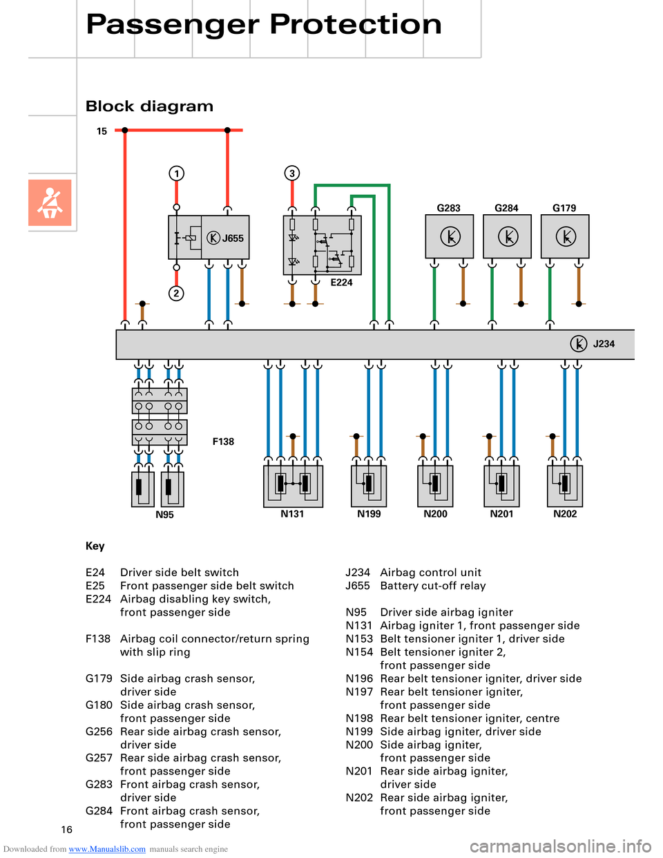
Key
E24 Driver side belt switch
E25 Front passenger side belt switch
E224 Airbag disabling key switch,
front passenger side
F138 Airbag coil connector/return spring
with slip ring
G179 Side airbag crash sensor,
driver side
G180 Side airbag crash sensor,
front passenger side
G256 Rear side airbag crash sensor,
driver side
G257 Rear side airbag crash sensor,
front passenger side
G283 Front airbag crash sensor,
driver side
G284 Front airbag crash sensor,
front passenger side
Block diagram
Passenger Protection
J234 Airbag control unit
J655 Battery cut-off relay
N95 Driver side airbag igniter
N131 Airbag igniter 1, front passenger side
N153 Belt tensioner igniter 1, driver side
N154 Belt tensioner igniter 2,
front passenger side
N196 Rear belt tensioner igniter, driver side
N197 Rear belt tensioner igniter,
front passenger side
N198 Rear belt tensioner igniter, centre
N199 Side airbag igniter, driver side
N200 Side airbag igniter,
front passenger side
N201 Rear side airbag igniter,
driver side
N202 Rear side airbag igniter,
front passenger side
Page 22 of 96
Downloaded from www.Manualslib.com manuals search engine 22
Passenger Protection
15 30
+
-
31
J644
J655
43
B
1
2
A
TerminalPinInput/outputDescription
30, battery A Input
(screw connection)U
bat. term. 30/battery
87 B Output
(screw connection)Output
Terminal 15 1 Input
(plug connection)Positive power supply,
interruptible
Vehicle earth 2 Input
(plug connection)Earth from
airbag control unit J234
Crash signal 3 Input
(plug connection)Crash signal from
airbag control unit J234
Diagnosis 4 Input
(plug connection)Diagnostic wire from
airbag control unit J234
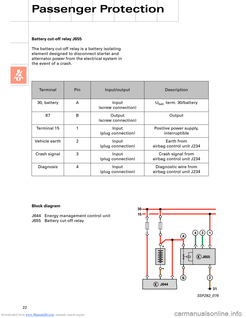
Battery cut-off relay J655
The battery cut-off relay is a battery isolating
element designed to disconnect starter and
alternator power from the electrical system in
the event of a crash.
Block diagram
J644 Energy management control unit
J655 Battery cut-off relay
SSP282_076
Page 43 of 96
Downloaded from www.Manualslib.com manuals search engine 43
D1
30
15
J329J53J695J694
75xE415
N376
6x
J623
J518
50R
50R
3
12
12
E408
STOP START
58s
210 210
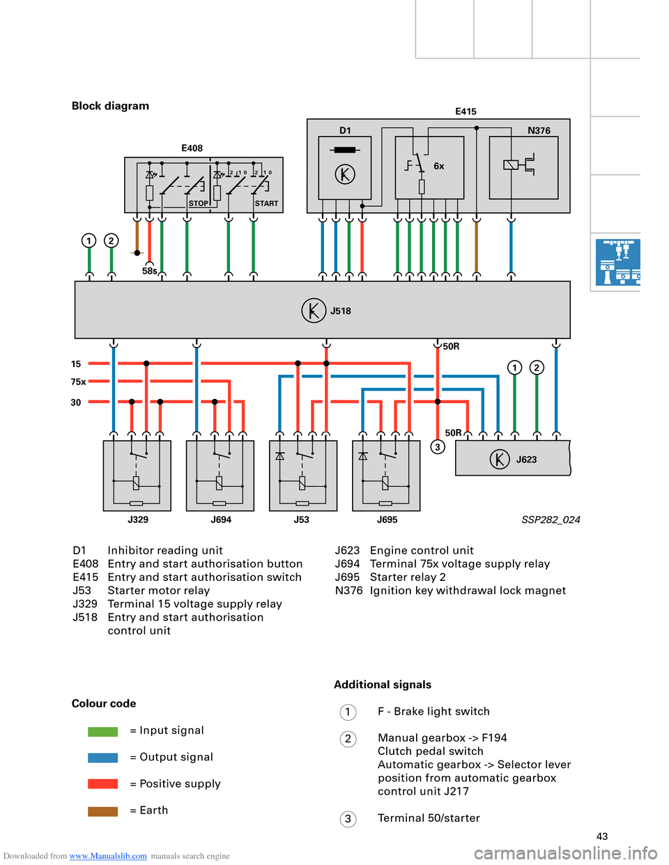
D1 Inhibitor reading unit
E408 Entry and start authorisation button
E415 Entry and start authorisation switch
J53 Starter motor relay
J329 Terminal 15 voltage supply relay
J518 Entry and start authorisation
control unit Block diagram
SSP282_024
Colour code
= Input signal
= Output signal
= Positive supply
= Earth
J623 Engine control unit
J694 Terminal 75x voltage supply relay
J695 Starter relay 2
N376 Ignition key withdrawal lock magnet
Additional signals
F - Brake light switch
Manual gearbox -> F194
Clutch pedal switch
Automatic gearbox -> Selector lever
position from automatic gearbox
control unit J217
Terminal 50/starter
1
2
3
Page 86 of 96
Downloaded from www.Manualslib.com manuals search engine 86
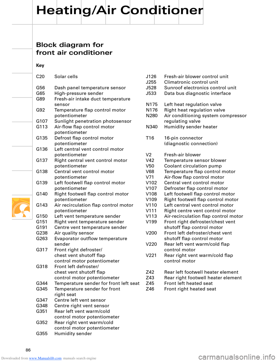
J126 Fresh-air blower control unit
J255 Climatronic control unit
J528 Sunroof electronics control unit
J533 Data bus diagnostic interface
N175 Left heat regulation valve
N176 Right heat regulation valve
N280 Air conditioning system compressor
regulating valve
N340 Humidity sender heater
T16 16-pin connector
(diagnostic connection)
V2 Fresh-air blower
V42 Temperature sensor blower
V50 Coolant circulation pump
V68 Temperature flap control motor
V71 Air-flow flap control motor
V102 Central vent control motor
V107 Defroster flap control motor
V108 Left footwell flap control motor
V109 Right footwell flap control motor
V110 Left central vent control motor
V111 Right centre vent control motor
V113 Air-recirculation flap control motor
V199 Front right defroster/chest vent
shutoff flap control motor
V200 Front left defroster/chest vent
shutoff flap control motor
V220 Rear left vent warm/cold flap
control motor
V221 Rear right vent warm/cold flap
control motor
Z42 Rear left footwell heater element
Z43 Rear right footwell heater element
Z45 Front left heated seat
Z46 Front right heated seat
Block diagram for
front air conditioner
Key
C20 Solar cells
G56 Dash panel temperature sensor
G65 High-pressure sender
G89 Fresh-air intake duct temperature
sensor
G92 Temperature flap control motor
potentiometer
G107 Sunlight penetration photosensor
G113 Air-flow flap control motor
potentiometer
G135 Defrost flap control motor
potentiometer
G136 Left central vent control motor
potentiometer
G137 Right central vent control motor
potentiometer
G138 Central vent control motor
potentiometer
G139 Left footwell flap control motor
potentiometer
G140 Right footwell flap control motor
potentiometer
G143 Air recirculation flap control motor
potentiometer
G150 Left vent temperature sender
G151 Right vent temperature sender
G191 Centre vent temperature sender
G238 Air quality sensor
G263 Evaporator outflow temperature
sender
G317 Front right defroster/
chest vent shutoff flap
control motor potentiometer
G318 Front left defroster/
chest vent shutoff flap
control motor potentiometer
G344 Temperature sender for front left seat
G345 Temperature sender for front
right seat
G347 Centre left vent sensor
G348 Centre right vent sensor
G351 Rear left vent warm/cold
control motor potentiometer
G352 Rear right vent warm/cold
control motor potentiometer
G355 Humidity sender
Heating/Air Conditioner
Page 88 of 96
Downloaded from www.Manualslib.com manuals search engine 88
Z12
E265
S
20A
30
G178
31
in out
G426 G427 V219
G349G350
M
V218
MJ533
S
15A
30
S
5A
15
G95
S
5A
3075
S
20A
S
5A
75
Z11 Z10V273G177G94
MM
V271
J674
J675
T16
Heating/Air Conditioner
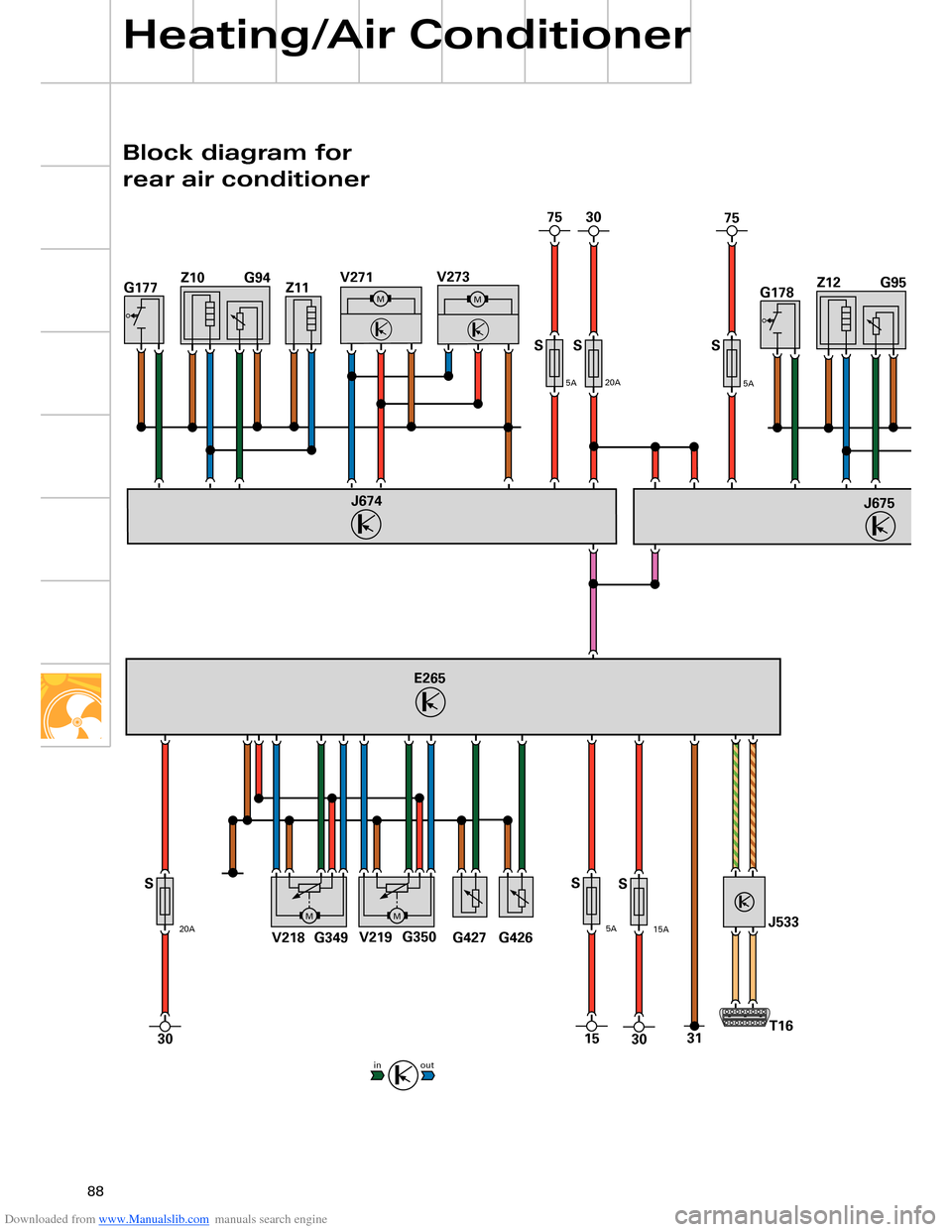
Block diagram for
rear air conditioner