fuel pump AUDI A8 2003 D3 / 2.G Technical Features Manual
[x] Cancel search | Manufacturer: AUDI, Model Year: 2003, Model line: A8, Model: AUDI A8 2003 D3 / 2.GPages: 96, PDF Size: 5.51 MB
Page 30 of 96
Downloaded from www.Manualslib.com manuals search engine 30
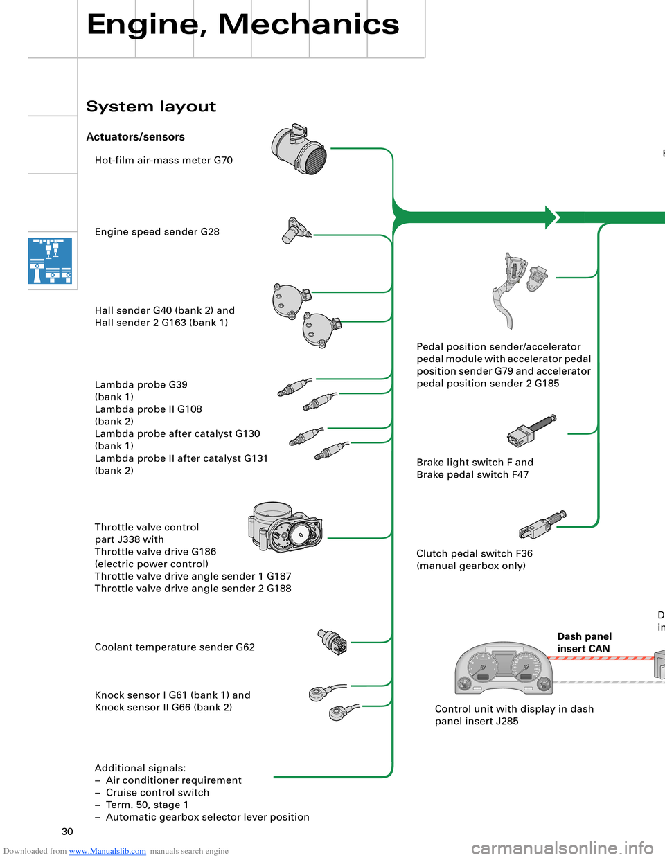
Hot-film air-mass meter G70
Engine speed sender G28
Hall sender G40 (bank 2) and
Hall sender 2 G163 (bank 1)
Lambda probe G39
(bank 1)
Lambda probe II G108
(bank 2)
Lambda probe after catalyst G130
(bank 1)
Lambda probe II after catalyst G131
(bank 2)
Throttle valve control
part J338 with
Throttle valve drive G186
(electric power control)
Throttle valve drive angle sender 1 G187
Throttle valve drive angle sender 2 G188
Coolant temperature sender G62
Knock sensor I G61 (bank 1) and
Knock sensor II G66 (bank 2)
Additional signals:
– Air conditioner requirement
– Cruise control switch
– Term. 50, stage 1
– Automatic gearbox selector lever positionEngine control unit J623
Steering
angle sender G85
ESP
control unit J104
Dash panel
insert CANAutomatic
gearbox
control unit J217
Airbag
control unit J234Intake manifold changeover valve
N156 and
Intake manifold changeover valve 2
N261
Left electrohydraulic engine mounting
solenoid valve N144 and
Right electrohydraulic engine mounting
solenoid valve N145
Torque rod valve N382
Lambda probe heater Z19
(bank 1) and
Lambda probe 2 heater Z28
(bank 2)
Lambda probe 1 heater
after catalyst Z29
Lambda probe 2 heater
after catalyst Z30
Additional signals:
– Starter relay term. 50, stage 2
– Tank leakage pump (USA only)
– Air conditioner compressor (out)Fuel pump relay J17
Fuel pump G6
Fuel pump II relay J49
Fuel pump G23
Injectors N30, N31, N32, N33 (bank 1)
Injectors N83, N84, N85, N86 (bank 2)
Ignition coils N (no. 1 cyl.), N128 (no. 2 cyl.),
N158 (no. 3 cyl.), N163 (no. 4 cyl.)
Ignition coils N164 (no. 5 cyl.), N189 (no. 6 cyl.),
N190 (no. 7 cyl.), N191 (no. 8 cyl.)
Activated charcoal filter system solenoid
valve 1 N80
Secondary-air pump relay J299 and
Secondary-air pump motor V101
Secondary air inlet valve N112
Throttle valve control part J338
With throttle valve drive G186
Inlet camshaft timing adjustment valve 1
N205 (bank 1)
and
N208 (bank 2) Pedal position sender/accelerator
pedal module with accelerator pedal
position sender G79 and accelerator
pedal position sender 2 G185
Brake light switch F and
Brake pedal switch F47
Clutch pedal switch F36
(manual gearbox only)
Control unit with display in dash
panel insert J285Data bus diagnostic
interface J533
Engine, Mechanics
System layout
Actuators/sensors
SSP282_091 Drive system CAN
Diagnosis CAN
Page 31 of 96
Downloaded from www.Manualslib.com manuals search engine 30
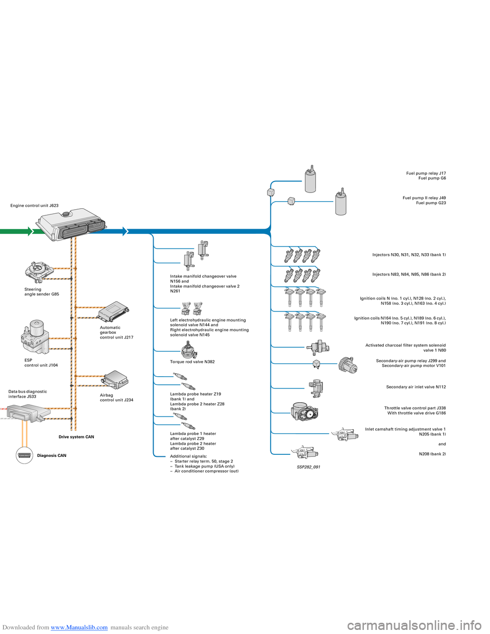
Hot-film air-mass meter G70
Engine speed sender G28
Hall sender G40 (bank 2) and
Hall sender 2 G163 (bank 1)
Lambda probe G39
(bank 1)
Lambda probe II G108
(bank 2)
Lambda probe after catalyst G130
(bank 1)
Lambda probe II after catalyst G131
(bank 2)
Throttle valve control
part J338 with
Throttle valve drive G186
(electric power control)
Throttle valve drive angle sender 1 G187
Throttle valve drive angle sender 2 G188
Coolant temperature sender G62
Knock sensor I G61 (bank 1) and
Knock sensor II G66 (bank 2)
Additional signals:
– Air conditioner requirement
– Cruise control switch
– Term. 50, stage 1
– Automatic gearbox selector lever positionEngine control unit J623
Steering
angle sender G85
ESP
control unit J104
Dash panel
insert CANAutomatic
gearbox
control unit J217
Airbag
control unit J234Intake manifold changeover valve
N156 and
Intake manifold changeover valve 2
N261
Left electrohydraulic engine mounting
solenoid valve N144 and
Right electrohydraulic engine mounting
solenoid valve N145
Torque rod valve N382
Lambda probe heater Z19
(bank 1) and
Lambda probe 2 heater Z28
(bank 2)
Lambda probe 1 heater
after catalyst Z29
Lambda probe 2 heater
after catalyst Z30
Additional signals:
– Starter relay term. 50, stage 2
– Tank leakage pump (USA only)
– Air conditioner compressor (out)Fuel pump relay J17
Fuel pump G6
Fuel pump II relay J49
Fuel pump G23
Injectors N30, N31, N32, N33 (bank 1)
Injectors N83, N84, N85, N86 (bank 2)
Ignition coils N (no. 1 cyl.), N128 (no. 2 cyl.),
N158 (no. 3 cyl.), N163 (no. 4 cyl.)
Ignition coils N164 (no. 5 cyl.), N189 (no. 6 cyl.),
N190 (no. 7 cyl.), N191 (no. 8 cyl.)
Activated charcoal filter system solenoid
valve 1 N80
Secondary-air pump relay J299 and
Secondary-air pump motor V101
Secondary air inlet valve N112
Throttle valve control part J338
With throttle valve drive G186
Inlet camshaft timing adjustment valve 1
N205 (bank 1)
and
N208 (bank 2) Pedal position sender/accelerator
pedal module with accelerator pedal
position sender G79 and accelerator
pedal position sender 2 G185
Brake light switch F and
Brake pedal switch F47
Clutch pedal switch F36
(manual gearbox only)
Control unit with display in dash
panel insert J285Data bus diagnostic
interface J533
Engine, Mechanics
System layout
Actuators/sensors
SSP282_091 Drive system CAN
Diagnosis CAN
Page 34 of 96
Downloaded from www.Manualslib.com manuals search engine 34
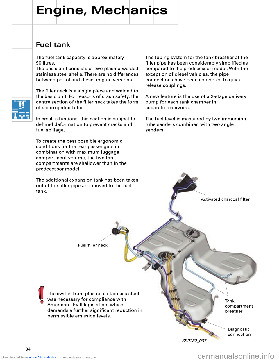
The tubing system for the tank breather at the
filler pipe has been considerably simplified as
compared to the predecessor model. With the
exception of diesel vehicles, the pipe
connections have been converted to quick-
release couplings.
A new feature is the use of a 2-stage delivery
pump for each tank chamber in
separate reservoirs.
The fuel level is measured by two immersion
tube senders combined with two angle
senders.
Engine, Mechanics
SSP282_007
Fuel tank
The fuel tank capacity is approximately
90 litres.
The basic unit consists of two plasma-welded
stainless steel shells. There are no differences
between petrol and diesel engine versions.
The filler neck is a single piece and welded to
the basic unit. For reasons of crash safety, the
centre section of the filler neck takes the form
of a corrugated tube.
In crash situations, this section is subject to
defined deformation to prevent cracks and
fuel spillage.
To create the best possible ergonomic
conditions for the rear passengers in
combination with maximum luggage
compartment volume, the two tank
compartments are shallower than in the
predecessor model.
The additional expansion tank has been taken
out of the filler pipe and moved to the fuel
tank.
The switch from plastic to stainless steel
was necessary for compliance with
American LEV II legislation, which
demands a further significant reduction in
permissible emission levels.
Activated charcoal filter
Fuel filler neck
Tank
compartment
breather
Diagnostic
connection
Page 35 of 96
Downloaded from www.Manualslib.com manuals search engine 35
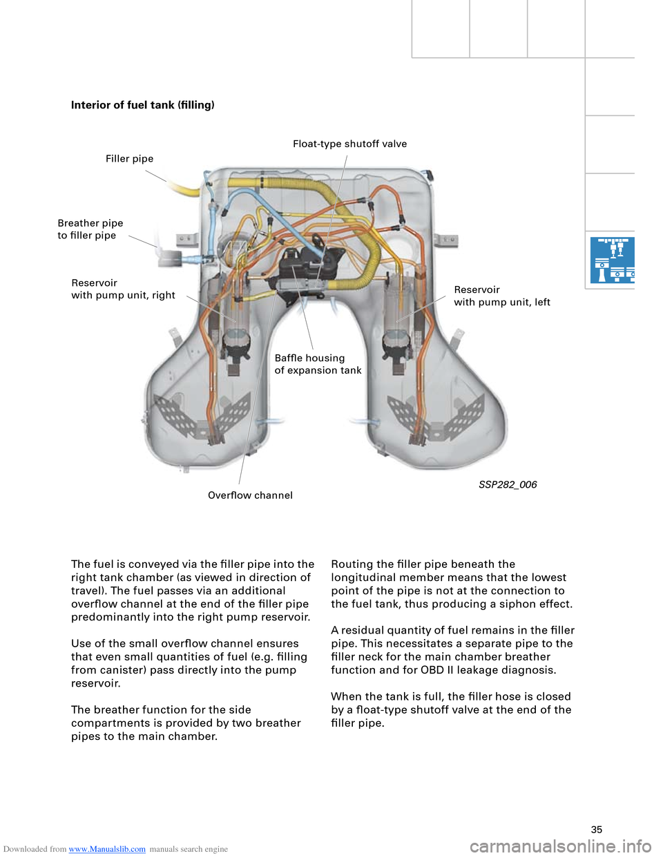
The fuel is conveyed via the filler pipe into the
right tank chamber (as viewed in direction of
travel). The fuel passes via an additional
overflow channel at the end of the filler pipe
predominantly into the right pump reservoir.
Use of the small overflow channel ensures
that even small quantities of fuel (e.g. filling
from canister) pass directly into the pump
reservoir.
The breather function for the side
compartments is provided by two breather
pipes to the main chamber.Routing the filler pipe beneath the
longitudinal member means that the lowest
point of the pipe is not at the connection to
the fuel tank, thus producing a siphon effect.
A residual quantity of fuel remains in the filler
pipe. This necessitates a separate pipe to the
filler neck for the main chamber breather
function and for OBD II leakage diagnosis.
When the tank is full, the filler hose is closed
by a float-type shutoff valve at the end of the
filler pipe. Interior of fuel tank (filling)
SSP282_006
Baffle housing
of expansion tankReservoir
with pump unit, left Reservoir
with pump unit, rightFloat-type shutoff valve
Breather pipe
to filler pipe
Overflow channel Filler pipe
Page 36 of 96
Downloaded from www.Manualslib.com manuals search engine 36
Engine, Mechanics
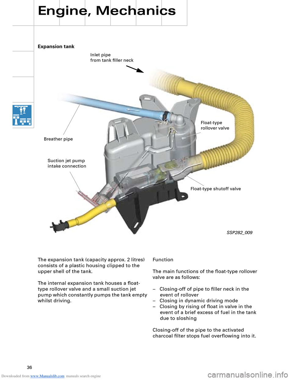
Function
The main functions of the float-type rollover
valve are as follows:
– Closing-off of pipe to filler neck in the
event of rollover
– Closing in dynamic driving mode
– Closing by rising of float in valve in the
event of a brief excess of fuel in the tank
due to sloshing
Closing-off of the pipe to the activated
charcoal filter stops fuel overflowing into it. Expansion tank
The expansion tank (capacity approx. 2 litres)
consists of a plastic housing clipped to the
upper shell of the tank.
The internal expansion tank houses a float-
type rollover valve and a small suction jet
pump which constantly pumps the tank empty
whilst driving.
SSP282_009
Inlet pipe
from tank filler neck
Float-type
rollover valve
Float-type shutoff valve Breather pipe
Suction jet pump
intake connection
Page 37 of 96
Downloaded from www.Manualslib.com manuals search engine 37
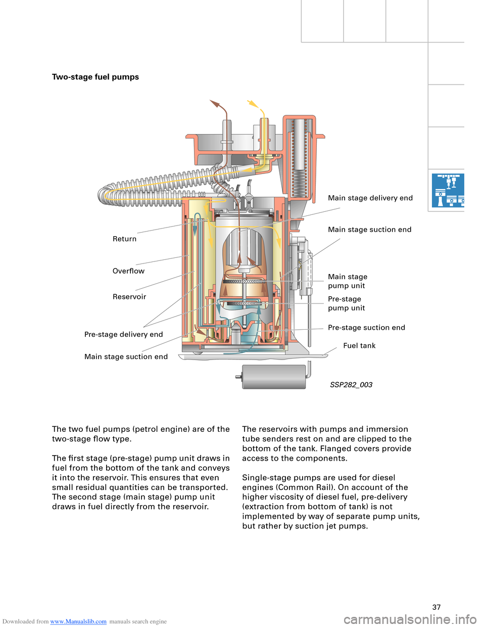
The reservoirs with pumps and immersion
tube senders rest on and are clipped to the
bottom of the tank. Flanged covers provide
access to the components.
Single-stage pumps are used for diesel
engines (Common Rail). On account of the
higher viscosity of diesel fuel, pre-delivery
(extraction from bottom of tank) is not
implemented by way of separate pump units,
but rather by suction jet pumps. Two-stage fuel pumps
The two fuel pumps (petrol engine) are of the
two-stage flow type.
The first stage (pre-stage) pump unit draws in
fuel from the bottom of the tank and conveys
it into the reservoir. This ensures that even
small residual quantities can be transported.
The second stage (main stage) pump unit
draws in fuel directly from the reservoir.
SSP282_003
Main stage delivery end
Main stage suction end
Main stage
pump unit
Pre-stage
pump unit
Pre-stage suction end
Fuel tank
Main stage suction end Pre-stage delivery endReservoirOverflow Return
Page 38 of 96
Downloaded from www.Manualslib.com manuals search engine 38
Engine, Mechanics
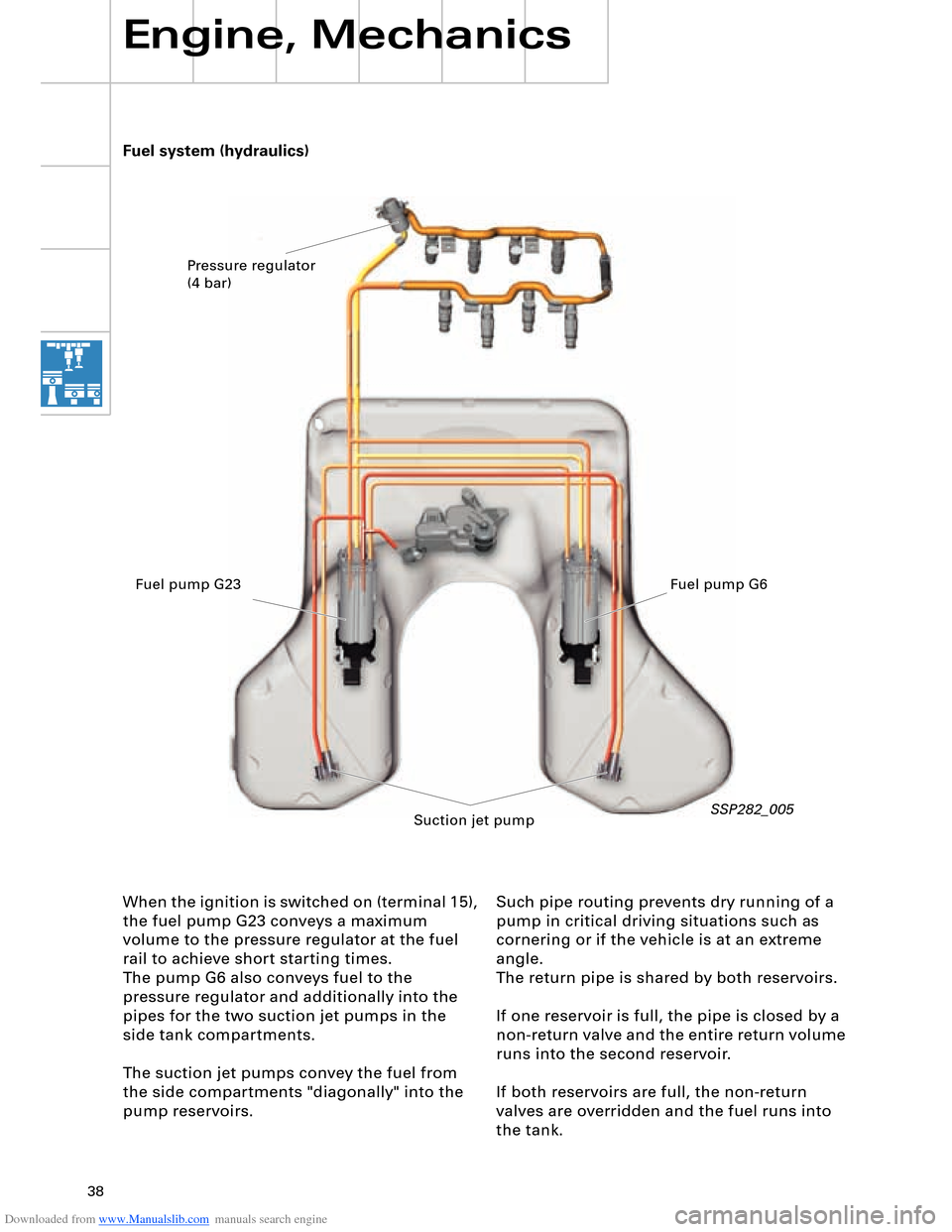
Such pipe routing prevents dry running of a
pump in critical driving situations such as
cornering or if the vehicle is at an extreme
angle.
The return pipe is shared by both reservoirs.
If one reservoir is full, the pipe is closed by a
non-return valve and the entire return volume
runs into the second reservoir.
If both reservoirs are full, the non-return
valves are overridden and the fuel runs into
the tank. Fuel system (hydraulics)
When the ignition is switched on (terminal 15),
the fuel pump G23 conveys a maximum
volume to the pressure regulator at the fuel
rail to achieve short starting times.
The pump G6 also conveys fuel to the
pressure regulator and additionally into the
pipes for the two suction jet pumps in the
side tank compartments.
The suction jet pumps convey the fuel from
the side compartments "diagonally" into the
pump reservoirs.
SSP282_005
Pressure regulator
(4 bar)
Fuel pump G23 Fuel pump G6
Suction jet pump
Page 39 of 96
Downloaded from www.Manualslib.com manuals search engine 39
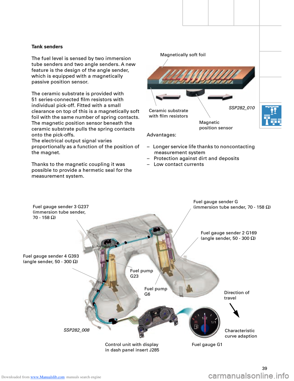
Advantages:
– Longer service life thanks to noncontacting
measurement system
– Protection against dirt and deposits
– Low contact currents
Tank senders
The fuel level is sensed by two immersion
tube senders and two angle senders. A new
feature is the design of the angle sender,
which is equipped with a magnetically
passive position sensor.
The ceramic substrate is provided with
51 series-connected film resistors with
individual pick-off. Fitted with a small
clearance on top of this is a magnetically soft
foil with the same number of spring contacts.
The magnetic position sensor beneath the
ceramic substrate pulls the spring contacts
onto the pick-offs.
The electrical output signal varies
proportionally as a function of the position of
the magnet.
Thanks to the magnetic coupling it was
possible to provide a hermetic seal for the
measurement system.
SSP282_010
SSP282_008
Magnetically soft foil
Ceramic substrate
with film resistors
Magnetic
position sensor
Fuel gauge sender 3 G237
(immersion tube sender,
70 - 158 W)
Fuel gauge sender 4 G393
(angle sender, 50 - 300 W)Fuel gauge sender G
(immersion tube sender, 70 - 158 W)
Fuel gauge sender 2 G169
(angle sender, 50 - 300 W)
Characteristic
curve adaption Direction of
travel
Control unit with display
in dash panel insert J285Fuel gauge G1 Fuel pump
G23
Fuel pump
G6
Page 91 of 96
Downloaded from www.Manualslib.com manuals search engine 91
4.2 Auxiliary heating sequence
The level of fuel in the tank is
interrogated. If the fuel tank is "empty",
the auxiliary heating function is not
permitted and the auxiliary heater symbol
in the dash panel insert goes out. "Empty"
roughly corresponds to the red display
zone. The energy management control
unit J644 checks whether there is
sufficient energy to accept auxiliary
heating. If this is the case, the auxiliary
heater is switched on in the various
operating modes depending on the
characteristic temperature curve and the
fresh-air blower is actuated.
If the auxiliary heating temperature
reaches a level of 30 °C, the fresh-air
blower is activated and the coolant
shutoff valve N279 pulsed in line with the
characteristic curve.
The auxiliary heater is switched off
automatically on completion of the operating
time transmitted by the MMI system to the
Climatronic control unit or it can be switched
off using the remote control OFF button.
Auxiliary heater circulation pump control
To speed up heating of the passenger
compartment and to achieve a better "heat
yield" in the air conditioner unit heat
exchanger, the circulation pump V55 and
coolant shutoff valve N279 are pulsed as a
function of water temperature and the
heating circuit flow rate is thus reduced.
An electric circulation pump is used for the
auxiliary heater. It is not possible to reduce
the supply voltage in the auxiliary heater
control unit and the circulation pump is thus
actuated at specific intervals to decrease its
output.
Additional control curve for "auxiliary heater"
and "additional heater"
When the engine is on, the auxiliary heater
and engine temperatures are constantly
compared. A switch to the large coolant
circuit is made as soon as the engine
temperature exceeds the auxiliary heater
temperature.
Activation of auxiliary heater circulation
pump with engine on
(pulsed operation of circulation pump)
In order to be able to ensure a sufficient flow
of water through the heat exchanger, the
auxiliary heater circulation pump must
additionally be switched on, as is the case for
instance with the 12-cylinder engine.If the engine is switched off again and not
all additional heater criteria (temperature,
time) are satisfied, the auxiliary heater
remains in operation for any residual
operating time before being deactivated.
This function can be encoded.