steering AUDI A8 2003 D3 / 2.G Technical Features Manual
[x] Cancel search | Manufacturer: AUDI, Model Year: 2003, Model line: A8, Model: AUDI A8 2003 D3 / 2.GPages: 96, PDF Size: 5.51 MB
Page 15 of 96
Downloaded from www.Manualslib.com manuals search engine 15
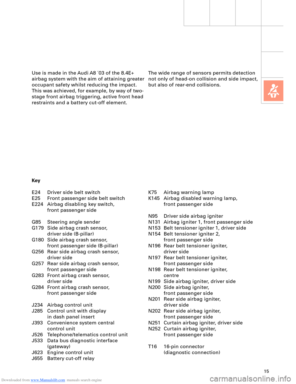
The wide range of sensors permits detection
not only of head-on collision and side impact,
but also of rear-end collisions. Use is made in the Audi A8 ´03 of the 8.4E+
airbag system with the aim of attaining greater
occupant safety whilst reducing the impact.
This was achieved, for example, by way of two-
stage front airbag triggering, active front head
restraints and a battery cut-off element.
K75 Airbag warning lamp
K145 Airbag disabled warning lamp,
front passenger side
N95 Driver side airbag igniter
N131 Airbag igniter 1, front passenger side
N153 Belt tensioner igniter 1, driver side
N154 Belt tensioner igniter 2,
front passenger side
N196 Rear belt tensioner igniter,
driver side
N197 Rear belt tensioner igniter,
front passenger side
N198 Rear belt tensioner igniter,
centre
N199 Side airbag igniter, driver side
N200 Side airbag igniter,
front passenger side
N201 Rear side airbag igniter,
driver side
N202 Rear side airbag igniter,
front passenger side
N251 Curtain airbag igniter, driver side
N252 Curtain airbag igniter,
front passenger side
T16 16-pin connector
(diagnostic connection) Key
E24 Driver side belt switch
E25 Front passenger side belt switch
E224 Airbag disabling key switch,
front passenger side
G85 Steering angle sender
G179 Side airbag crash sensor,
driver side (B-pillar)
G180 Side airbag crash sensor,
front passenger side (B-pillar)
G256 Rear side airbag crash sensor,
driver side
G257 Rear side airbag crash sensor,
front passenger side
G283 Front airbag crash sensor,
driver side
G284 Front airbag crash sensor,
front passenger side
J234 Airbag control unit
J285 Control unit with display
in dash panel insert
J393 Convenience system central
control unit
J526 Telephone/telematics control unit
J533 Data bus diagnostic interface
(gateway)
J623 Engine control unit
J655 Battery cut-off relay
Page 18 of 96
Downloaded from www.Manualslib.com manuals search engine 18
Safety systems
2-stage front airbags
The 2-stage triggering of the front airbags
provides optimum restraint in crash
situations at around 30 km/h. There is a
separate firing pellet for each stage in the
driver's and front passenger's airbag. These
ignite successively at specified time intervals.
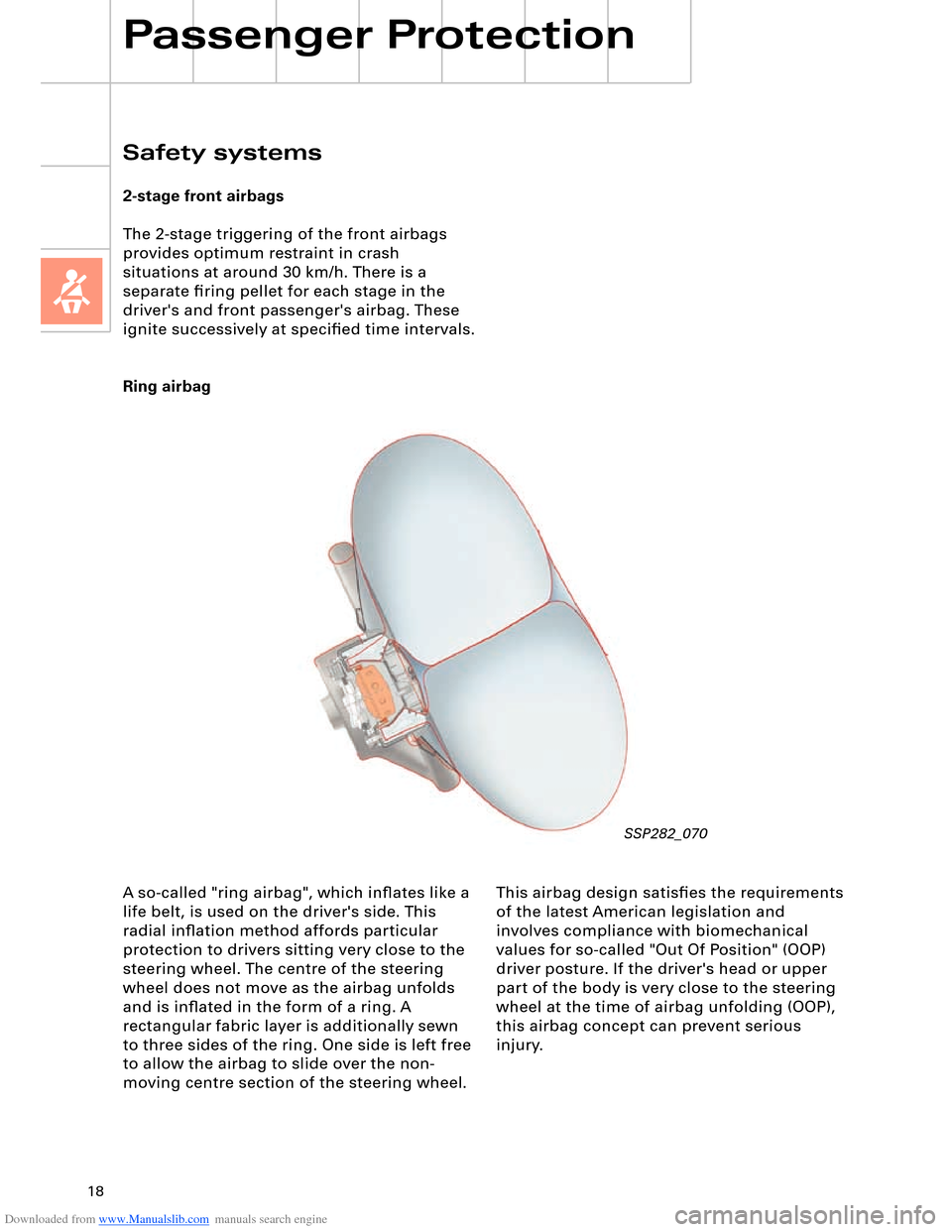
Ring airbag
Passenger Protection
SSP282_070
A so-called "ring airbag", which inflates like a
life belt, is used on the driver's side. This
radial inflation method affords particular
protection to drivers sitting very close to the
steering wheel. The centre of the steering
wheel does not move as the airbag unfolds
and is inflated in the form of a ring. A
rectangular fabric layer is additionally sewn
to three sides of the ring. One side is left free
to allow the airbag to slide over the non-
moving centre section of the steering wheel. This airbag design satisfies the requirements
of the latest American legislation and
involves compliance with biomechanical
values for so-called "Out Of Position" (OOP)
driver posture. If the driver's head or upper
part of the body is very close to the steering
wheel at the time of airbag unfolding (OOP),
this airbag concept can prevent serious
injury.
Page 30 of 96
Downloaded from www.Manualslib.com manuals search engine 30
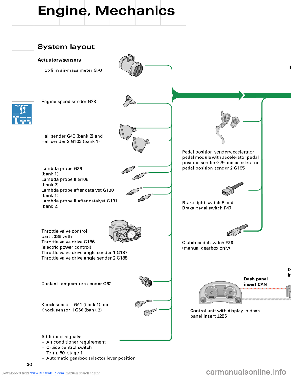
Hot-film air-mass meter G70
Engine speed sender G28
Hall sender G40 (bank 2) and
Hall sender 2 G163 (bank 1)
Lambda probe G39
(bank 1)
Lambda probe II G108
(bank 2)
Lambda probe after catalyst G130
(bank 1)
Lambda probe II after catalyst G131
(bank 2)
Throttle valve control
part J338 with
Throttle valve drive G186
(electric power control)
Throttle valve drive angle sender 1 G187
Throttle valve drive angle sender 2 G188
Coolant temperature sender G62
Knock sensor I G61 (bank 1) and
Knock sensor II G66 (bank 2)
Additional signals:
– Air conditioner requirement
– Cruise control switch
– Term. 50, stage 1
– Automatic gearbox selector lever positionEngine control unit J623
Steering
angle sender G85
ESP
control unit J104
Dash panel
insert CANAutomatic
gearbox
control unit J217
Airbag
control unit J234Intake manifold changeover valve
N156 and
Intake manifold changeover valve 2
N261
Left electrohydraulic engine mounting
solenoid valve N144 and
Right electrohydraulic engine mounting
solenoid valve N145
Torque rod valve N382
Lambda probe heater Z19
(bank 1) and
Lambda probe 2 heater Z28
(bank 2)
Lambda probe 1 heater
after catalyst Z29
Lambda probe 2 heater
after catalyst Z30
Additional signals:
– Starter relay term. 50, stage 2
– Tank leakage pump (USA only)
– Air conditioner compressor (out)Fuel pump relay J17
Fuel pump G6
Fuel pump II relay J49
Fuel pump G23
Injectors N30, N31, N32, N33 (bank 1)
Injectors N83, N84, N85, N86 (bank 2)
Ignition coils N (no. 1 cyl.), N128 (no. 2 cyl.),
N158 (no. 3 cyl.), N163 (no. 4 cyl.)
Ignition coils N164 (no. 5 cyl.), N189 (no. 6 cyl.),
N190 (no. 7 cyl.), N191 (no. 8 cyl.)
Activated charcoal filter system solenoid
valve 1 N80
Secondary-air pump relay J299 and
Secondary-air pump motor V101
Secondary air inlet valve N112
Throttle valve control part J338
With throttle valve drive G186
Inlet camshaft timing adjustment valve 1
N205 (bank 1)
and
N208 (bank 2) Pedal position sender/accelerator
pedal module with accelerator pedal
position sender G79 and accelerator
pedal position sender 2 G185
Brake light switch F and
Brake pedal switch F47
Clutch pedal switch F36
(manual gearbox only)
Control unit with display in dash
panel insert J285Data bus diagnostic
interface J533
Engine, Mechanics
System layout
Actuators/sensors
SSP282_091 Drive system CAN
Diagnosis CAN
Page 31 of 96
Downloaded from www.Manualslib.com manuals search engine 30
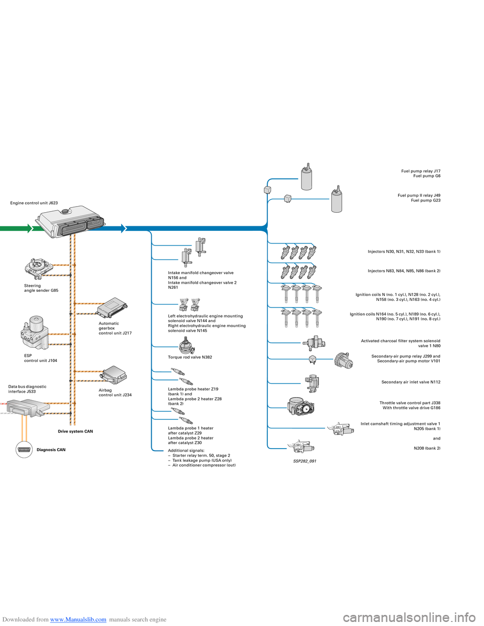
Hot-film air-mass meter G70
Engine speed sender G28
Hall sender G40 (bank 2) and
Hall sender 2 G163 (bank 1)
Lambda probe G39
(bank 1)
Lambda probe II G108
(bank 2)
Lambda probe after catalyst G130
(bank 1)
Lambda probe II after catalyst G131
(bank 2)
Throttle valve control
part J338 with
Throttle valve drive G186
(electric power control)
Throttle valve drive angle sender 1 G187
Throttle valve drive angle sender 2 G188
Coolant temperature sender G62
Knock sensor I G61 (bank 1) and
Knock sensor II G66 (bank 2)
Additional signals:
– Air conditioner requirement
– Cruise control switch
– Term. 50, stage 1
– Automatic gearbox selector lever positionEngine control unit J623
Steering
angle sender G85
ESP
control unit J104
Dash panel
insert CANAutomatic
gearbox
control unit J217
Airbag
control unit J234Intake manifold changeover valve
N156 and
Intake manifold changeover valve 2
N261
Left electrohydraulic engine mounting
solenoid valve N144 and
Right electrohydraulic engine mounting
solenoid valve N145
Torque rod valve N382
Lambda probe heater Z19
(bank 1) and
Lambda probe 2 heater Z28
(bank 2)
Lambda probe 1 heater
after catalyst Z29
Lambda probe 2 heater
after catalyst Z30
Additional signals:
– Starter relay term. 50, stage 2
– Tank leakage pump (USA only)
– Air conditioner compressor (out)Fuel pump relay J17
Fuel pump G6
Fuel pump II relay J49
Fuel pump G23
Injectors N30, N31, N32, N33 (bank 1)
Injectors N83, N84, N85, N86 (bank 2)
Ignition coils N (no. 1 cyl.), N128 (no. 2 cyl.),
N158 (no. 3 cyl.), N163 (no. 4 cyl.)
Ignition coils N164 (no. 5 cyl.), N189 (no. 6 cyl.),
N190 (no. 7 cyl.), N191 (no. 8 cyl.)
Activated charcoal filter system solenoid
valve 1 N80
Secondary-air pump relay J299 and
Secondary-air pump motor V101
Secondary air inlet valve N112
Throttle valve control part J338
With throttle valve drive G186
Inlet camshaft timing adjustment valve 1
N205 (bank 1)
and
N208 (bank 2) Pedal position sender/accelerator
pedal module with accelerator pedal
position sender G79 and accelerator
pedal position sender 2 G185
Brake light switch F and
Brake pedal switch F47
Clutch pedal switch F36
(manual gearbox only)
Control unit with display in dash
panel insert J285Data bus diagnostic
interface J533
Engine, Mechanics
System layout
Actuators/sensors
SSP282_091 Drive system CAN
Diagnosis CAN
Page 58 of 96
Downloaded from www.Manualslib.com manuals search engine 58
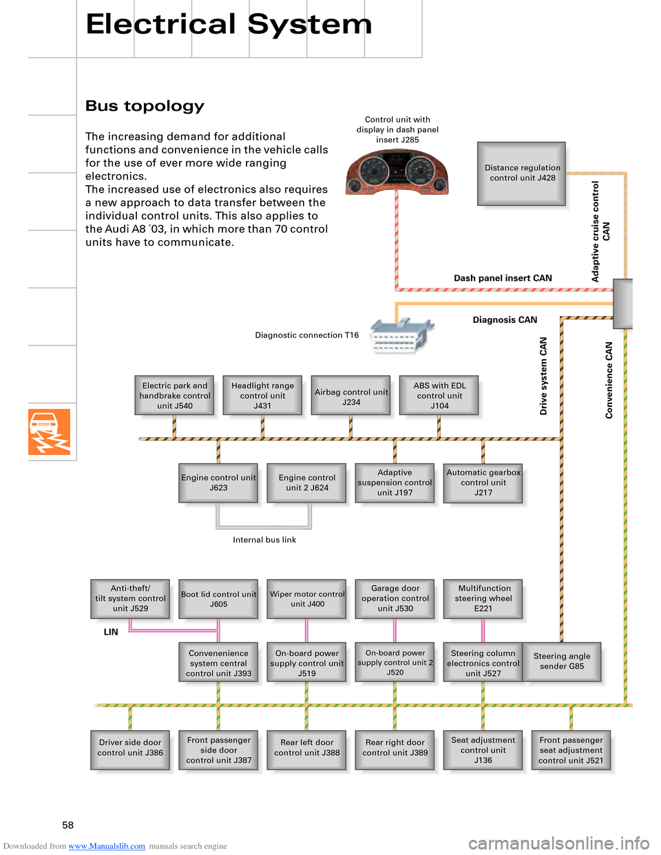
Bus topology
Electrical System
The increasing demand for additional
functions and convenience in the vehicle calls
for the use of ever more wide ranging
electronics.
The increased use of electronics also requires
a new approach to data transfer between the
individual control units. This also applies to
the Audi A8 ´03, in which more than 70 control
units have to communicate.
Distance regulation
control unit J428
Electric park and
handbrake control
unit J540Headlight range
control unit
J431Airbag control unit
J234ABS with EDL
control unit
J104
Engine control unit
J623Adaptive
suspension control
unit J197 Engine control
unit 2 J624Automatic gearbox
control unit
J217
Anti-theft/
tilt system control
unit J529
Boot lid control unit
J605Wiper motor control
unit J400Garage door
operation control
unit J530 Multifunction
steering wheel
E221
Convenenience
system central
control unit J393On-board power
supply control unit
J519
On-board power
supply control unit 2
J520Steering column
electronics control
unit J527Steering angle
sender G85
Driver side door
control unit J386Front passenger
side door
control unit J387Rear left door
control unit J388Rear right door
control unit J389Seat adjustment
control unit
J136Front passenger
seat adjustment
control unit J521 Control unit with
display in dash panel
insert J285
Diagnostic connection T16
Dash panel insert CAN
Drive system CAN
Diagnosis CAN
Convenience CAN
Internal bus link
LIN
Adaptive cruise control
CAN
Page 65 of 96
Downloaded from www.Manualslib.com manuals search engine 65
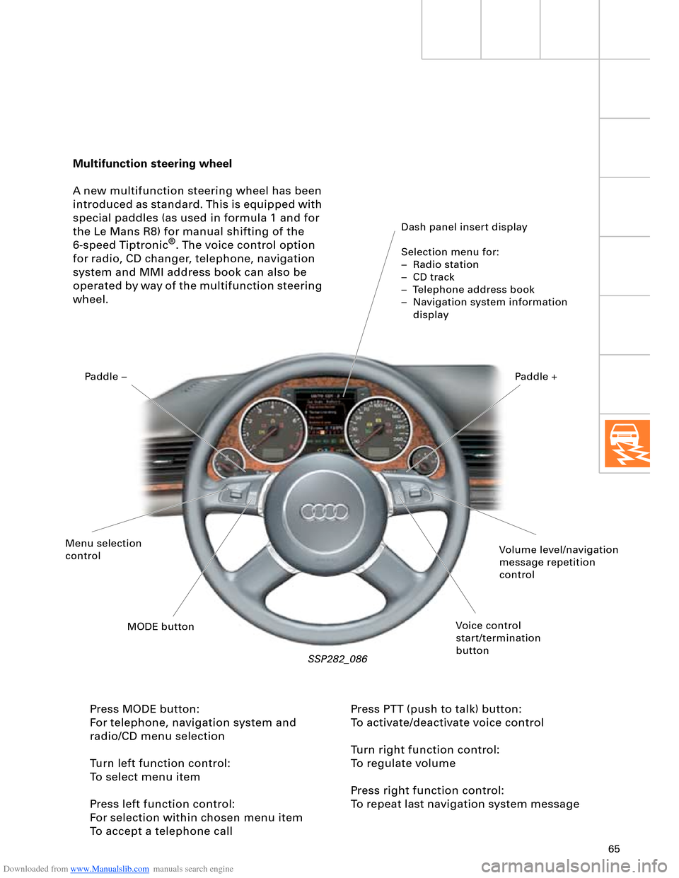
Multifunction steering wheel
A new multifunction steering wheel has been
introduced as standard. This is equipped with
special paddles (as used in formula 1 and for
the Le Mans R8) for manual shifting of the
6-speed Tiptronic
®. The voice control option
for radio, CD changer, telephone, navigation
system and MMI address book can also be
operated by way of the multifunction steering
wheel.
Dash panel insert display
Selection menu for:
– Radio station
– CD track
– Telephone address book
– Navigation system information
display
SSP282_086
Press MODE button:
For telephone, navigation system and
radio/CD menu selection
Turn left function control:
To select menu item
Press left function control:
For selection within chosen menu item
To accept a telephone callPress PTT (push to talk) button:
To activate/deactivate voice control
Turn right function control:
To regulate volume
Press right function control:
To repeat last navigation system message
Volume level/navigation
message repetition
control
Voice control
start/termination
button MODE button Menu selection
controlPaddle –Paddle +
Page 69 of 96
Downloaded from www.Manualslib.com manuals search engine 69
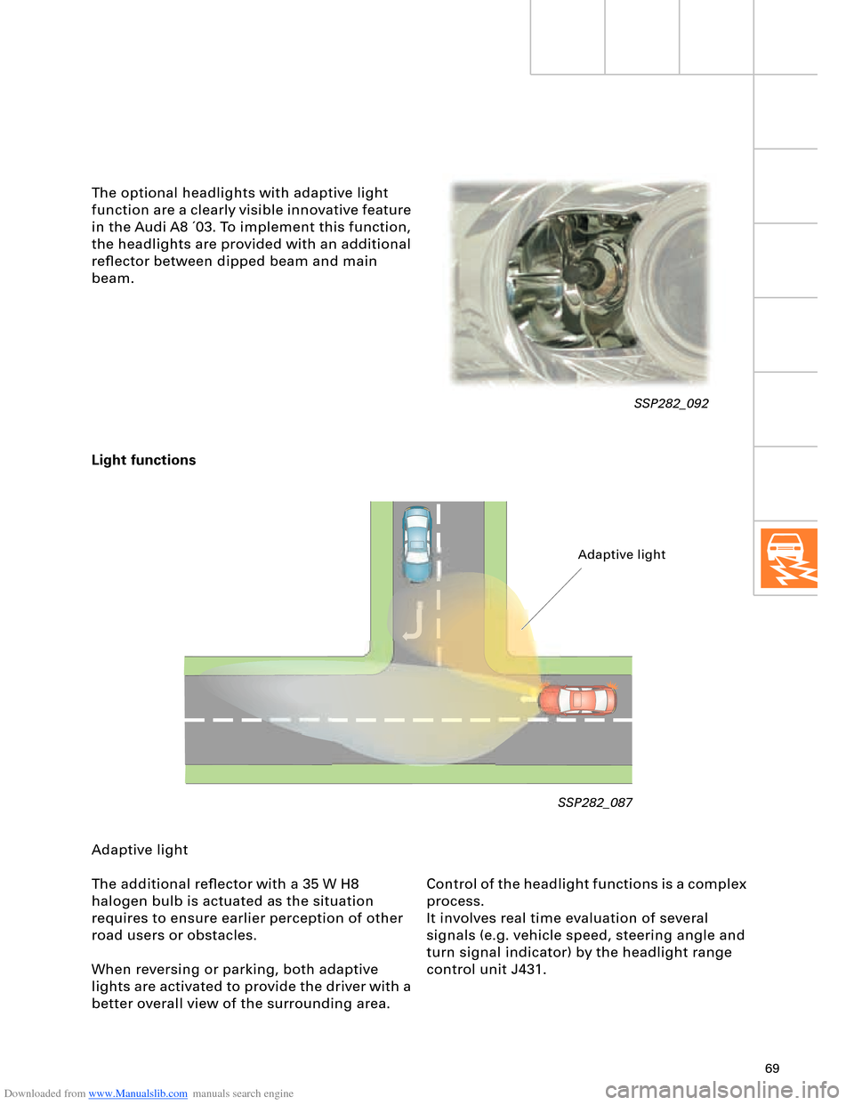
Light functions
SSP282_087
Adaptive light
The additional reflector with a 35 W H8
halogen bulb is actuated as the situation
requires to ensure earlier perception of other
road users or obstacles.
When reversing or parking, both adaptive
lights are activated to provide the driver with a
better overall view of the surrounding area.
Adaptive light
Control of the headlight functions is a complex
process.
It involves real time evaluation of several
signals (e.g. vehicle speed, steering angle and
turn signal indicator) by the headlight range
control unit J431.
SSP282_092
The optional headlights with adaptive light
function are a clearly visible innovative feature
in the Audi A8 ´03. To implement this function,
the headlights are provided with an additional
reflector between dipped beam and main
beam.