wing AUDI A8 2003 D3 / 2.G Technical Features Manual
[x] Cancel search | Manufacturer: AUDI, Model Year: 2003, Model line: A8, Model: AUDI A8 2003 D3 / 2.GPages: 96, PDF Size: 5.51 MB
Page 2 of 96
Downloaded from www.Manualslib.com manuals search engine Complete vehicle information
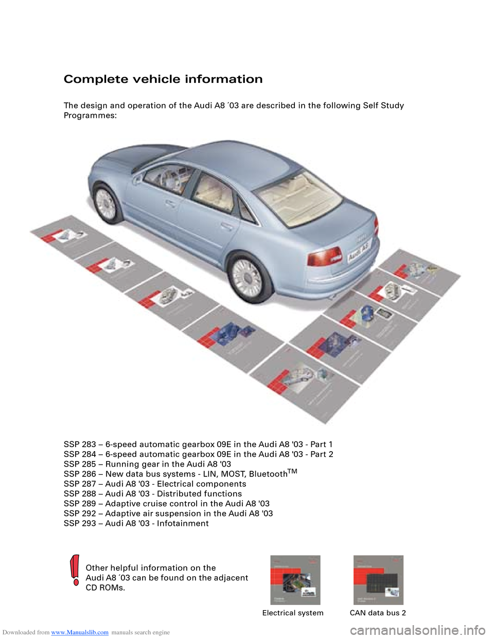
The design and operation of the Audi A8 ´03 are described in the following Self Study
Programmes:
Other helpful information on the
Audi A8 ´03 can be found on the adjacent
CD ROMs.
Electrical system CAN data bus 2
SSP 283 – 6-speed automatic gearbox 09E in the Audi A8 '03 - Part 1
SSP 284 – 6-speed automatic gearbox 09E in the Audi A8 '03 - Part 2
SSP 285 – Running gear in the Audi A8 '03
SSP 286 – New data bus systems - LIN, MOST, Bluetooth
TM
SSP 287 – Audi A8 '03 - Electrical components
SSP 288 – Audi A8 '03 - Distributed functions
SSP 289 – Adaptive cruise control in the Audi A8 '03
SSP 292 – Adaptive air suspension in the Audi A8 '03
SSP 293 – Audi A8 '03 - Infotainment
Page 13 of 96
Downloaded from www.Manualslib.com manuals search engine 13
Seats
A new seat concept was developed for the
Audi A8 ´03.
The basic seat features the following
standard functions:
– Electric seat length, height and angle
adjustment
– Electric backrest angle adjustment
– Front crash-active head restraints (refer to
Page 21)
The basic seat can additionally be fitted with
– Four-way lumbar support
– Seat memory for driver and front
passenger
– Electrically adjustable head restraints
– Electric belt height adjustersExtra features of sports and comfort seats:
– Electric top 1/3 backrest adjustment
– Electric seat depth adjustment
Optional extras for comfort seat:
– Climate function (refer to Page 85)
– and/or massage function
The massage function is implemented by way
of rhythmic action of the electromechanical
lumbar support, thus massaging and relaxing
the back muscles.
The fixed rear seat bench versions correspond
to those of the front seats, with the third head
restraint being fully retractable. Electric
individual seats are however only available as
"Basic" and "Comfort" versions.
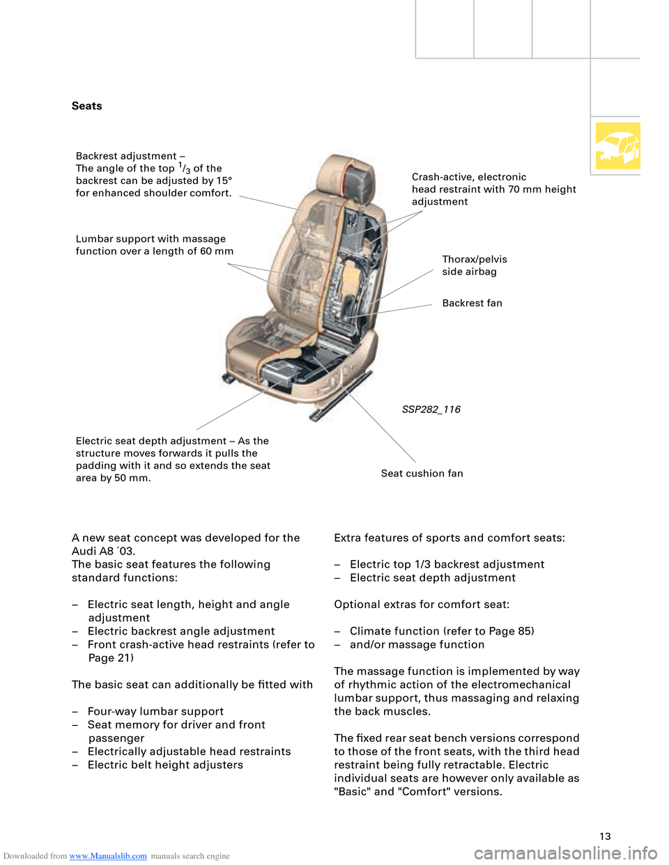
SSP282_116
Crash-active, electronic
head restraint with 70 mm height
adjustment
Thorax/pelvis
side airbag
Backrest fan
Seat cushion fan Electric seat depth adjustment – As the
structure moves forwards it pulls the
padding with it and so extends the seat
area by 50 mm. Backrest adjustment –
The angle of the top
1/3 of the
backrest can be adjusted by 15°
for enhanced shoulder comfort.
Lumbar support with massage
function over a length of 60 mm
Page 23 of 96
Downloaded from www.Manualslib.com manuals search engine 23
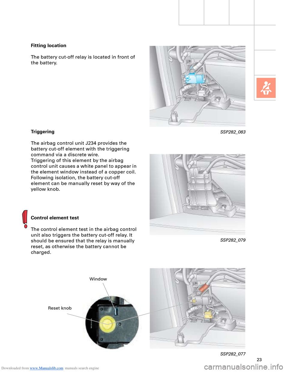
Fitting location
The battery cut-off relay is located in front of
the battery.
Triggering
The airbag control unit J234 provides the
battery cut-off element with the triggering
command via a discrete wire.
Triggering of this element by the airbag
control unit causes a white panel to appear in
the element window instead of a copper coil.
Following isolation, the battery cut-off
element can be manually reset by way of the
yellow knob.
Control element test
The control element test in the airbag control
unit also triggers the battery cut-off relay. It
should be ensured that the relay is manually
reset, as otherwise the battery cannot be
charged.
SSP282_079
SSP282_077
SSP282_083
Reset knobWindow
Page 26 of 96
Downloaded from www.Manualslib.com manuals search engine 26
Engine, Mechanics
V8 5V 3.7 l/4.2 l engine
The 3.7 l and 4.2 l V8 engines were adopted
from the predecessor model with certain
modifications.
These modifications relate to the intake and
exhaust systems and are described in the
following.Design and operation are described in
SSP 217.
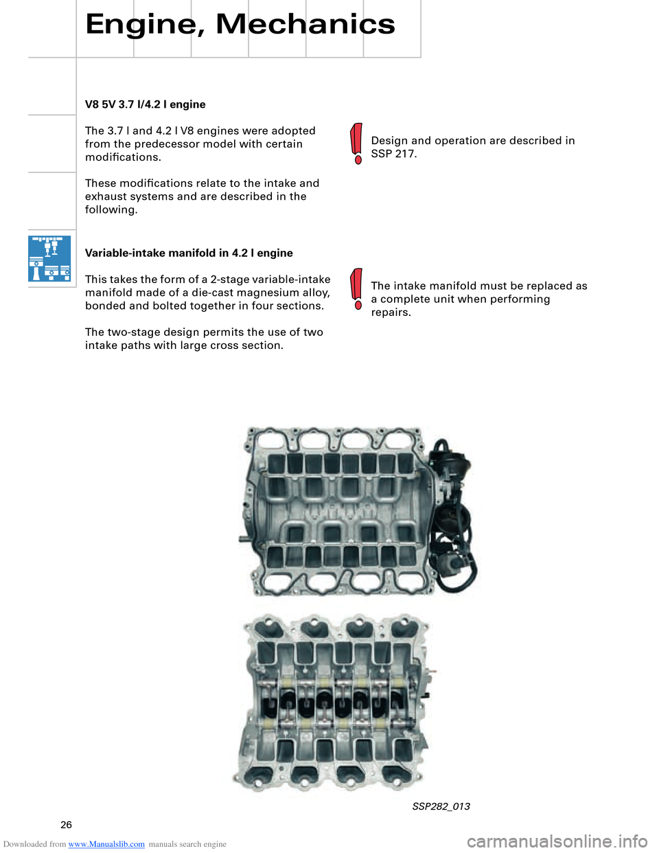
Variable-intake manifold in 4.2 l engine
This takes the form of a 2-stage variable-intake
manifold made of a die-cast magnesium alloy,
bonded and bolted together in four sections.
The two-stage design permits the use of two
intake paths with large cross section.The intake manifold must be replaced as
a complete unit when performing
repairs.
SSP282_013
Page 27 of 96
Downloaded from www.Manualslib.com manuals search engine 27
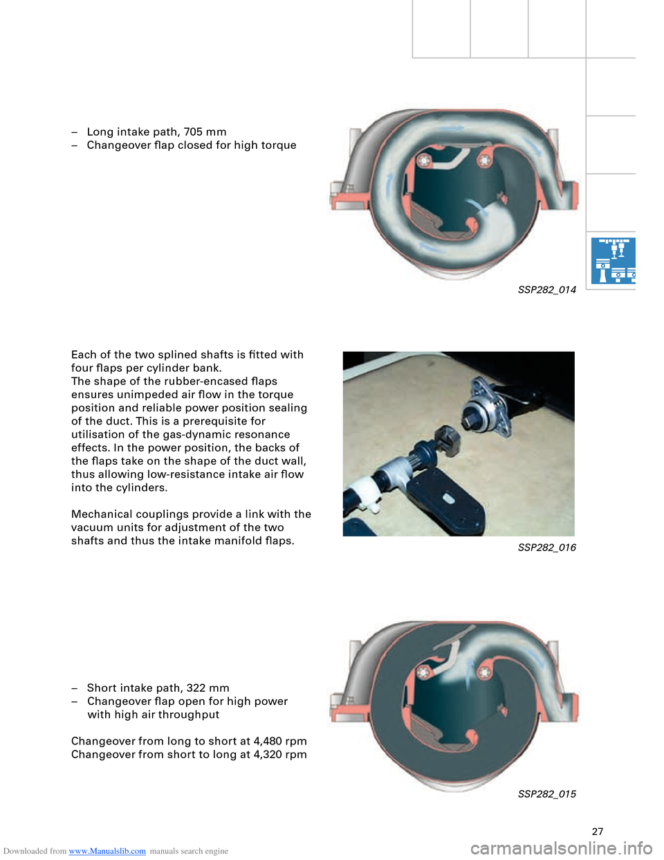
– Long intake path, 705 mm
– Changeover flap closed for high torque
Each of the two splined shafts is fitted with
four flaps per cylinder bank.
The shape of the rubber-encased flaps
ensures unimpeded air flow in the torque
position and reliable power position sealing
of the duct. This is a prerequisite for
utilisation of the gas-dynamic resonance
effects. In the power position, the backs of
the flaps take on the shape of the duct wall,
thus allowing low-resistance intake air flow
into the cylinders.
Mechanical couplings provide a link with the
vacuum units for adjustment of the two
shafts and thus the intake manifold flaps.
– Short intake path, 322 mm
– Changeover flap open for high power
with high air throughput
Changeover from long to short at 4,480 rpm
Changeover from short to long at 4,320 rpm
SSP282_014
SSP282_016
SSP282_015
Page 36 of 96
Downloaded from www.Manualslib.com manuals search engine 36
Engine, Mechanics
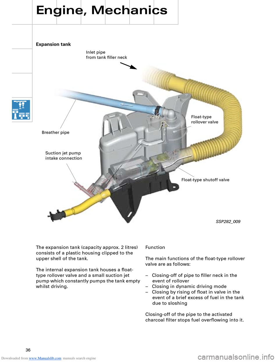
Function
The main functions of the float-type rollover
valve are as follows:
– Closing-off of pipe to filler neck in the
event of rollover
– Closing in dynamic driving mode
– Closing by rising of float in valve in the
event of a brief excess of fuel in the tank
due to sloshing
Closing-off of the pipe to the activated
charcoal filter stops fuel overflowing into it. Expansion tank
The expansion tank (capacity approx. 2 litres)
consists of a plastic housing clipped to the
upper shell of the tank.
The internal expansion tank houses a float-
type rollover valve and a small suction jet
pump which constantly pumps the tank empty
whilst driving.
SSP282_009
Inlet pipe
from tank filler neck
Float-type
rollover valve
Float-type shutoff valve Breather pipe
Suction jet pump
intake connection
Page 41 of 96
Downloaded from www.Manualslib.com manuals search engine 41
Automatically controlled
starting
The automatic start control is integrated into
the engine control unit.
A new feature is that starter control is no
longer implemented by way of the ignition/
starter switch D (switching of terminal 50),
but rather it is performed automatically by
the engine control unit.
Release for starter actuation is always
transmitted by the entry and start
authorisation control unit J518 to the engine
control unit J623.
In addition to general release by the
immobilizer, the following start release
conditions also have to be satisfied:
– Start signal from entry and start
authorisation switch E415 or entry and
start authorisation button E408
– Clutch pedal pressed, signal from clutch
pedal switch F194 (manual gearbox only)
– Selector lever position P or N (automatic
gearbox control unit J217)
– In the event of start signal via entry and
start authorisation button E408, brake
must be pressed (signal from brake light
switch F via separate interface)
As a safeguard, P/N signal or signal from
clutch pedal switch F194 must be applied
to the separate interfaces of the two
control units (J623 and J518).
Additional safeguard, as entry and start
authorisation button E408 can be
actuated by front passenger.
1
2 1
1
2
Page 42 of 96
Downloaded from www.Manualslib.com manuals search engine 42
Engine, Mechanics
Sequence of operations
1 Entry and start authorisation switch E415/entry and start authorisation button E408
2 Entry and start authorisation control unit J518
The entry and start authorisation control
unit checks for authorisation – in the form
of information on selector slide position N
or P – from the automatic gearbox control
unit J217 and for brake application in the
case of a start signal from the entry and
start authorisation button E408.
3 Engine control unit J623 Application of selector slide position P/N or
"clutch pressed" information to the engine
control unit (separate interface) causes the
two starter relays J53 and J695 to be
actuated simultaneously. The relays then
switch terminal 50 for starter actuation.
The starter operates and cranks the engine.
On exceeding a defined engine speed, the
engine control unit J623 recognises that
the engine has started and the relays are
deenergised (thus terminating starting
process).
As a safeguard, two relays are connected in
series. In the event of fusion welding of the
make contacts (relay remains closed
following deenergisation), the engine
control unit J623 can thus interrupt the
circuit (terminal 50) by way of the other
relay in each case.
The two relays are deenergised alternately
in order to ensure even make contact wear
(break spark) in both relays. The
deenergisation sequence alternates. The driver triggers a brief start signal
(min. 20 ms) by turning the ignition key to
start position or by pressing the entry and
start authorisation button E408.
If the start prerequisites have been
satisfied, the entry and start authorisation
control unit J518 transmits a start request
– terminal 50 ON – to the engine control
unit J623.
The entry and start authorisation control unit J518 also controls the terminal 15 and
terminal 75x circuits.
Relay operation is monitored and faults diagnosed by evaluating the alternating
deenergisation with the aid of the terminal
50R interface.
The terminal 50R interface represents a link
with terminal 50 and provides the engine
control unit J623 with feedback for start
control/diagnosis.
Automatically controlled starting is not
permitted in the event of undervoltage or a
system fault.
The engine can however be started
manually by way of corresponding start
signal actuation.
To relieve the load on the starter and
battery, the relay actuation time is
limited to approx. 10 seconds per starting
operation (automatic or manual starting).
Page 48 of 96
Downloaded from www.Manualslib.com manuals search engine 48
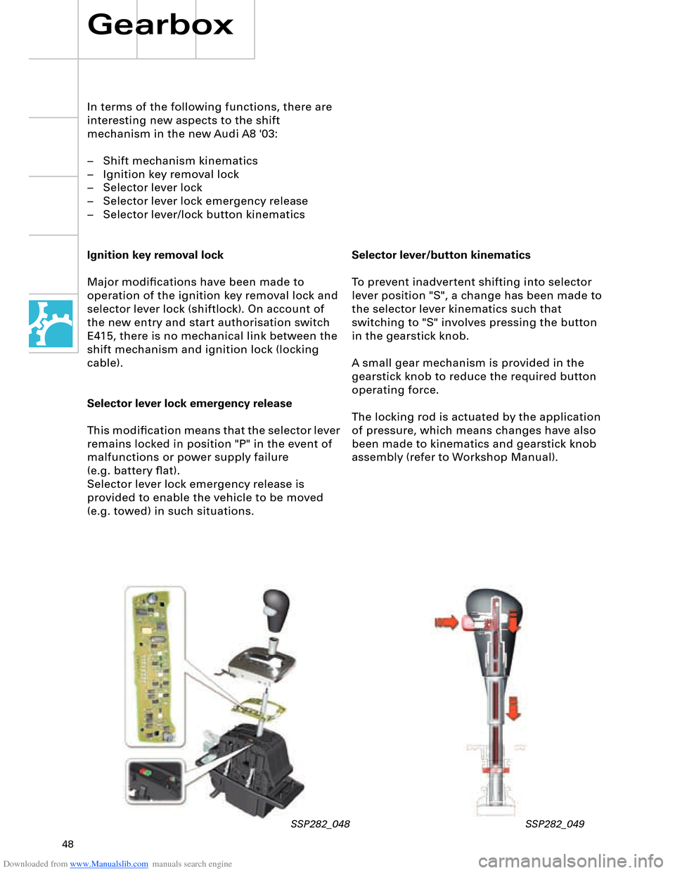
Selector lever/button kinematics
To prevent inadvertent shifting into selector
lever position "S", a change has been made to
the selector lever kinematics such that
switching to "S" involves pressing the button
in the gearstick knob.
A small gear mechanism is provided in the
gearstick knob to reduce the required button
operating force.
The locking rod is actuated by the application
of pressure, which means changes have also
been made to kinematics and gearstick knob
assembly (refer to Workshop Manual).
In terms of the following functions, there are
interesting new aspects to the shift
mechanism in the new Audi A8 '03:
– Shift mechanism kinematics
– Ignition key removal lock
– Selector lever lock
– Selector lever lock emergency release
– Selector lever/lock button kinematics
Ignition key removal lock
Major modifications have been made to
operation of the ignition key removal lock and
selector lever lock (shiftlock). On account of
the new entry and start authorisation switch
E415, there is no mechanical link between the
shift mechanism and ignition lock (locking
cable).
Selector lever lock emergency release
This modification means that the selector lever
remains locked in position "P" in the event of
malfunctions or power supply failure
(e.g. battery flat).
Selector lever lock emergency release is
provided to enable the vehicle to be moved
(e.g. towed) in such situations.
Gearbox
SSP282_048 SSP282_049
Page 53 of 96
Downloaded from www.Manualslib.com manuals search engine 53
The following functions are provided by the
electric parking brake:
– Parking brake function
– Emergency braking function
– Holding function when driving off on a hill
– Brake pad wear indicator
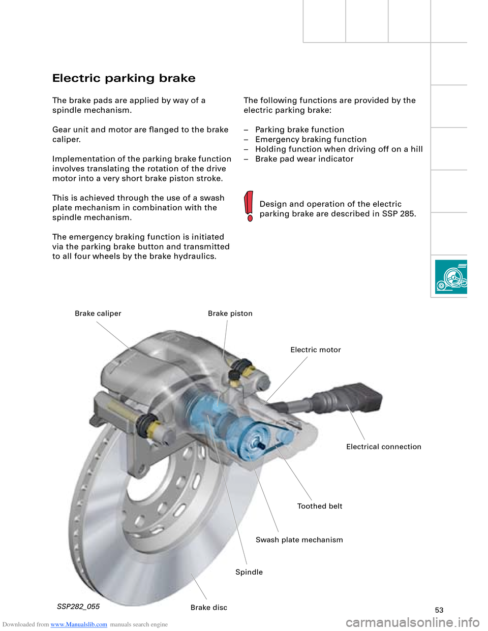
Electric parking brake
The brake pads are applied by way of a
spindle mechanism.
Gear unit and motor are flanged to the brake
caliper.
Implementation of the parking brake function
involves translating the rotation of the drive
motor into a very short brake piston stroke.
This is achieved through the use of a swash
plate mechanism in combination with the
spindle mechanism.
The emergency braking function is initiated
via the parking brake button and transmitted
to all four wheels by the brake hydraulics.
Design and operation of the electric
parking brake are described in SSP 285.
SSP282_055
Toothed belt
Swash plate mechanismElectric motor Brake piston
SpindleElectrical connection
Brake disc Brake caliper