display AUDI A8 2012 User Guide
[x] Cancel search | Manufacturer: AUDI, Model Year: 2012, Model line: A8, Model: AUDI A8 2012Pages: 300, PDF Size: 75.06 MB
Page 28 of 300
26 Instruments and warning /indicator lights
After abo ut 5 seconds the display sw itches
back to normal. The distance and time re
maining are updated eac h time the ignition is
switched on until the date due for service is
reached .
Service due
When the due date for service is reached , the
message
Serv ice due! appears in the instr u
ment cluster immediately after you switch the
ignit io n on . Additionally, a warning tone
sounds . After about
5 seconds the display
sw itches back to no rmal.
Calling up the service schedules
If or when an oil change or inspection is due,
can be shown in the MMI d isplay by select ing
the service interva l display in the car menu .
Select the
!CAR ! function button> Car sys
tems
co ntrol button > Servicing & checks >
Service interval disp lays.
Re setting the service interval display
Your author ized Audi dealer w ill reset the cor
responding service sched ule after performing
the app rop riate se rv ice on you r vehicle . You
a lso have the possibili ty to reset the o il
change sched ule after having performed an
oil c hange a ccor ding to Audi s pecifications.
Selec t the
I CAR I func tion button > Car sys
tems
c on trol b utt on > Servicing & checks >
Service interval displays > Reset oil change
inte rval.
{[) Note
If you disconnec t the b attery termi nals, no
calc ulations can be made for the serv ice
interva l display during this t ime and no
service rem inder w ill appea r. Remembe r
that obse rv in g the prope r se rv ice interva ls
is vitally impo rtant to extend ing the life of
your v eh icle, part icu larly the eng ine, and
main taini ng its va lue . Ev en i f th e m ileage
driv en is low, th e maximum per iod o f one
yea r from o ne se rvi ce to the nex t mus t not
be e xcee ded.
(D Tips
- Do not reset the display betwee n oil
c h anges, otherwise the d isp lay w ill be in
co rrect.
- Th e info rmation in the Se rvice Remin der
remains stored even w hen t he vehicle
battery is disconnected.
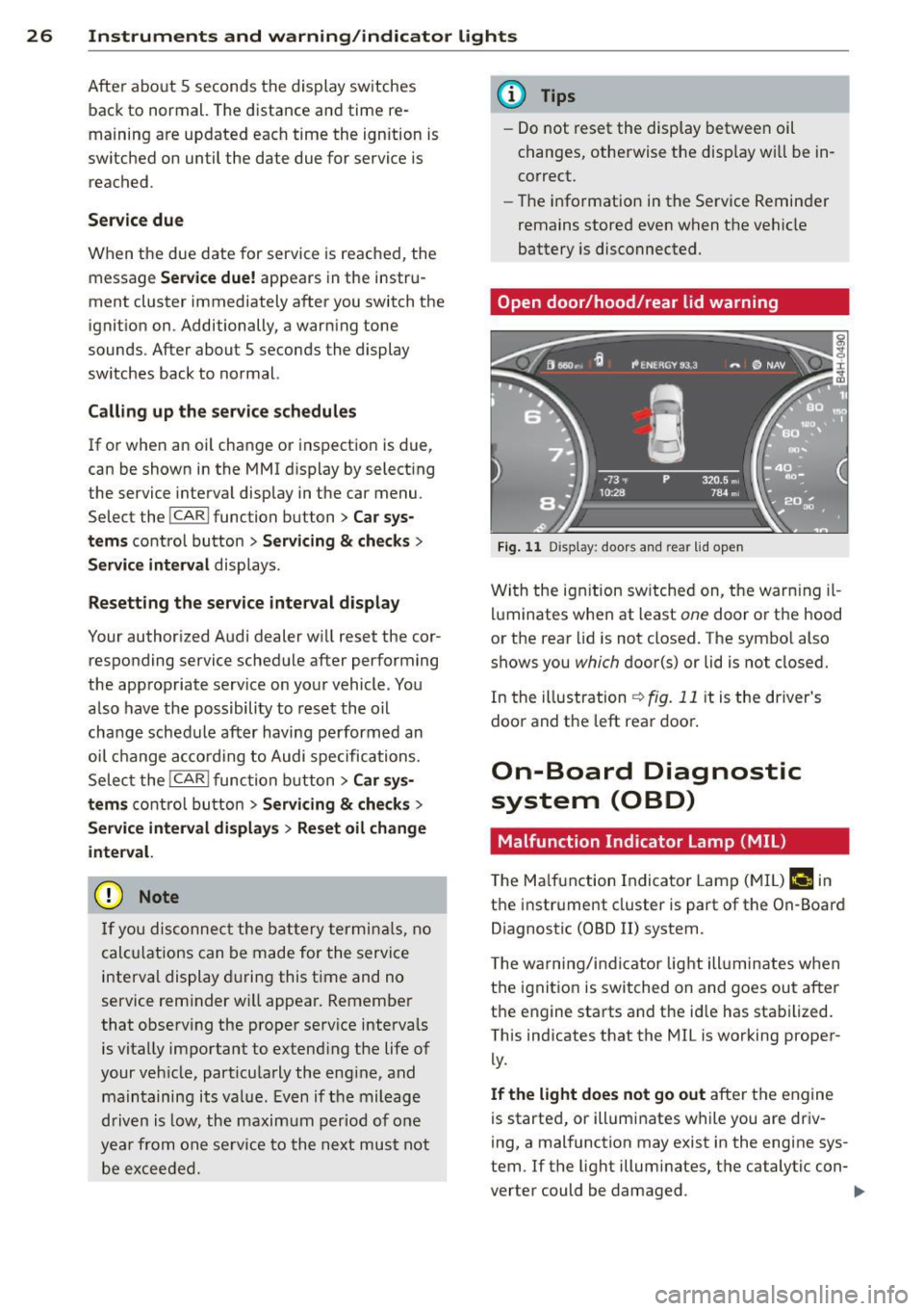
Open door /hood /rear lid warning
F ig. 1 1 Display : doors and rea r lid open
Wi th the ig nition sw itched on, t he warn ing il
lu minates when at least
one doo r or th e hood
or the rear lid is not closed. The sym bo l also
shows you
which d oor(s) or lid is not closed.
In the illustration
r:!> fig. 11 it is the driver's
doo randt he leftrea rdoo ~
On-Board Diagnostic
system (OBD)
Malfunction Ind icator Lamp (MIL )
The Ma lf u nction Indicator Lam p (M IL) f-4 in
t h e instr ume nt cluster is part of t he On -Board
Diagnostic (OBD
II) system .
T he wa rn ing /indic ator lig ht ill uminates when
the ignitio n is switched on and goes ou t after
t h e engine sta rts and t he id le has sta bilized.
This ind icates that the MIL is working proper
ly.
If the light does not go out afte r the e ngine
is starte d, or illumi nates w hile you are driv
i ng, a mal function may exist in the engine sys
tem . If t he light illum inates, t he catalytic con-
verter could be damaged .
IIJ,-
Page 29 of 300
Instruments and warning/indicator lights 2 7
Continue driving with reduced power (avoid
ing sustained high speeds and/or rapid accel
erat ions) and have the condition corrected.
Contact your author iz ed Audi dealer.
If the light ill uminates, the electronic speed
limiter may also be ma lfunctioning . For more
information ¢
page 2 7, Electronic speed
limiter .
An improperly closed fuel fi ller cap may also
cause the MIL light to ill uminate ¢
page 217.
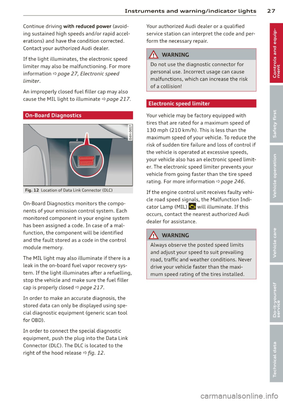
On-Board Diagnostics
Fig. 12 Loca tion of Data Li nk Connector (DLC)
On-Board Diagnostics monitors the compo
nents of yo ur emission control system. Each
mon itored component in your engine system
has been assigned a code. In case of a ma l
function, the component will be identified and the fault stored as a code in the contro l
module memory.
The MIL light may a lso illuminate if there is a
l eak in the on-board fue l vapor recovery sys
tem. If the light illuminates after a ref uelling,
stop the veh icle and make sure the fue l filler
cap is properly closed ¢
page 217.
In order to make an accurate diagnosis, the
stored data can only be displayed using spe
cial diagnostic equipment (gener ic scan tool
for OBD).
In order to connect the special diagnostic
eq uipment, push the plug into the Data Link
Connector (DLC). The DLC is located to the right of the hood release¢
fig. 12.
Your authorized Audi dea ler or a qualified
service station can interpret the code and per
form the necessary repair.
A WARNING
Do not use the diagnostic connector for
personal use. Incorrect usage can cause
malfunctions, wh ich can increase the risk
of a collision!
Electronic speed limiter
-
Your vehicle may be factory equipped w ith
t ir es that are rated fo r a maximum speed of
130 mph (210 km/h). This is less than the
maximum speed of your vehicle . To reduce the
risk of sudden tire fai lure and loss of control if
the vehicle is operated at excessive speeds,
your vehicle a lso has an e lectronic speed limit
er . The e lectronic speed limiter prevents your
vehicle from going faster than the tire speed rating . For more information ¢
page 246.
If the engine contro l unit receives faulty vehi
cle road speed signa ls, the Ma lfunction Indi·
cator Lamp (MIL)
fllllij w ill illuminate. If this
occurs, contact the nearest authorized Audi
dealer for assistance .
A WARNING
-
Always observe the posted speed limits
and adjust your speed to suit prevailing road, traffic and weather conditions. Never
drive your vehicle faster than the maxi
mum speed rating of the tires installed.
Page 31 of 300

Removing the mechanical key
Fig. 14 Remote control maste r key : re mov ing the me
c han ical key
• Press the release button@ ¢ fig. 14.
• Pull the mechanica l key @ out of the mas
ter key.
Using the mechan ica l key, you can:
- lock and unlock* the storage compartment
on the passenger's side
<=:> page 71.
-lock and unlock the vehicle manually
c:>page 33 .
-lock the front and rear passenger doors me
chanically
c:> page 34.
- unlock the rear lid manua lly ¢ page 37 .
Check light and battery in the master
key
Fig. 15 Remote master key : Re mov ing the battery
holder
Check light in the master key
The check light @<=:> fig. 15 in the master key
prov ides information about different cond i
tions.
• The check light turns on brief ly once when a
button is pressed, and during an "inqu iry"
by the convenience key system .
Opening and closing 29
• If the check light does not come on, the
battery is dead and has to be replaced. In
add ition, when the battery is dead
the m
indicator light appears in the instrument
cluster display as well as the message
Please change the key battery .
Master key battery replacement
We recommend having the battery changed
by an authorized Audi dealer. However, if you
wish to replace the dead battery yourse lf , pro
ceed as follows:
• Remove the mechanical key
c:> page 29.
.. Press the re lease button ® c:> fig. 15 on the
battery holder and at the same time pull the
battery holder out of the master key in the
direction of the arrow .
.. Install the new battery CR 2032 with the
"+" sign facing down.
• Push the battery holder carefu lly into the
master key.
• Install the mechan ical key.
(® For the sake of the environment
Dispose of dead batteries properly so as
not to poll ute the environment.
(D Tips
The replacement battery must be the
same specification as the original.
Electronic immobilizer
The immobilizer helps to prevent unauthor
ized use of your vehicle .
A computer chip inside your key automatically
deact ivates the electronic immobilizer when
the key is inside the vehicle . When you remove
the key from the vehicle, the elect ronic immo
bilizer is automatically activated once again.
& WARNING
Always take the key with you when you
leave the vehicle. The key can disarm the
e lectronic engine immobilizer and permit
an unauthorized person to start the engine
and enable operation of the vehicle
IIJI,-
Page 41 of 300

- The buttons for the power sun shades* in
the side windows,
- The buttons for the power sun shade* in the
rear window,
- Front passenger power seat adj ustment *
button.
_& WARNING
- When you leave your vehicle -even if on
ly briefly- always take the ignition key
with you. This applies particularly when
children remain in the veh icle. Otherw ise
the ch ildren could start the engine or op
erate electrical equ ipment (e.g. power
w indows) . The power windows are func
t ional until t he driver's door or passeng
er's door has been opened.
- Be careful when closing the windows.
Check to see that no one is in the way, or
serious injury could result!
- When lo cking the veh icle from outside,
t he ve hicle must be unocc upied s in ce the
w indows can no longer be opened in an
emergency.
(D Tips
- The dr iver can lower or raise the power
sun shades * in the side windows by us ing
swi tches © and
@.
-After the ignition has been switched off,
the windows can still be opened o r
closed for about 10 minutes . The powe r
windows are not switched off until the
driver's door or passenger's door has
been opened.
What to do after a malfunction
The one-touch open and close function must
be reactivated if the battery hos been discon
nected.
• Pull and hold the power window switch un
ti l the window is fully closed.
• Release the switch and then pull it again for
at least one second .
Openin g an d clos ing 39
Valet parking
The valet parking feature protects the lug
gage comportment from unauthorized ac
cess.
F ig. 30 Valet par king button
Wi th "valet parking" a ctivated, the rear lid
cannot be opened.
• Remove the mechanical key
c::;, page 29 .
• Open the glove compartment and activate
c::;, fig. 30 the "valet parking" feature by
pressing the
! VALET I b utton. The indicator
light in the swi tch illuminates.
• Close the glove compartment and lock it
w ith the mechanical key.
• Leave the master key with the se rvice per
sonnel for park ing and keep the mechanical
key with you.
When the "valet parking" feature is activated:
- the unlocki ng button fo r the rear l id
c:s in
the dr ive r's door is inactive
- the button
c:s on the mas ter key is inac tive
- the opening handle in the rear lid is inact ive .
The vehicle can be driven and locked and un
locked with the master key. Access to the lug
gage compartment is blocked.
When the valet parking function is switched
on, the message
Vale t par king acti vated ap
pears in the instrument cluster display when
you sw itch the ignition on.
Page 46 of 300
44 Clear vision
Highway light function* (vehicles with LED
headlights) -this function adapts the lighting
for highway driving based on vehicle speed.
.&_ WARNING
- Automatic headlights are only intended
to assist the driver. They do not relieve
the driver of his responsibility to check
the headlights and to turn them on man
ually according to the current light and
visibility conditions. For example, fog
cannot be detected by the light sensors.
So always switch on the headlights §.0
under these weather conditions and
when driving in the dark.
- Crashes can happen when you cannot see the road ahead and when you cannot be
seen by other motorists. Always turn on
the headlights so that you can see ahead
and so that others can see your car from
the back.
- Please observe legal regulations when
using the lighting systems described.
(D Note
The rear fog lights should only be turned
on in accordance with traffic regulation, as
the lights are bright for following traffic.
@ Tips
- The light sensor* for automatic dynamic
headlight range control* is located in the
rear view mirror mount. You should
therefore not apply any stickers to the
windshield in this area in order to pre
vent malfunctions or failures .
- In the event of a light sensor malfunc
tion, the driver is notified in the instru
ment cluster display¢
page 21 .
- You will hear a warning tone if you open
the driver door when the exterior lights
are switched on.
- In cool or damp weather, the inside of
the headlights, turn signals and tail
lights can fog over due to the tempera
ture difference between the inside and
outside. They will clear shortly after switching them on. This does not affect
the service life of the lighting.
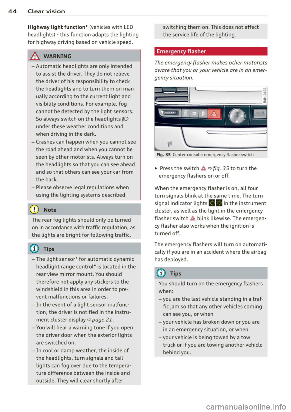
Emergency flasher
The emergency flasher makes other motorists
aware that you or your vehicle ore in an emer
gency situation.
,--~
,_'
. ;.' --- --~-.sc-
Fig. 35 Center console: emergency flasher switch
.,. Press the switch 11 ¢ fig. 35 to turn the
emergency flashers on or off .
When the emergency flasher is on, all four
turn signals blink at the same time. The turn
s ignal ind icator lights
ea in the instrument
cluster, as well as the light in the emergency
flasher switch
11 blink likewise. The emergen
cy flasher also works when the ignition is
turned off.
The emergency flashers will turn on automati
cally if you are in an accident where the airbag
has deployed.
(D Tips
You should turn on the emergency flashers
when:
- you are the last vehicle standing in a traf
fic jam so that any other vehicles coming
can see you, or when
- your vehicle has broken down or you are
in an emergency situation, or when
-your vehicle is being towed by a tow
truck or if you are towing another vehicle
behind you.
Page 49 of 300
Selecting a color pr ofile
You can select from the Iv ory , Polar and Ru
b y/ Pol ar
color profiles .
(D Tips
The settings are automa tically sto red and
assigned to the remote con tro l key that is
in use.
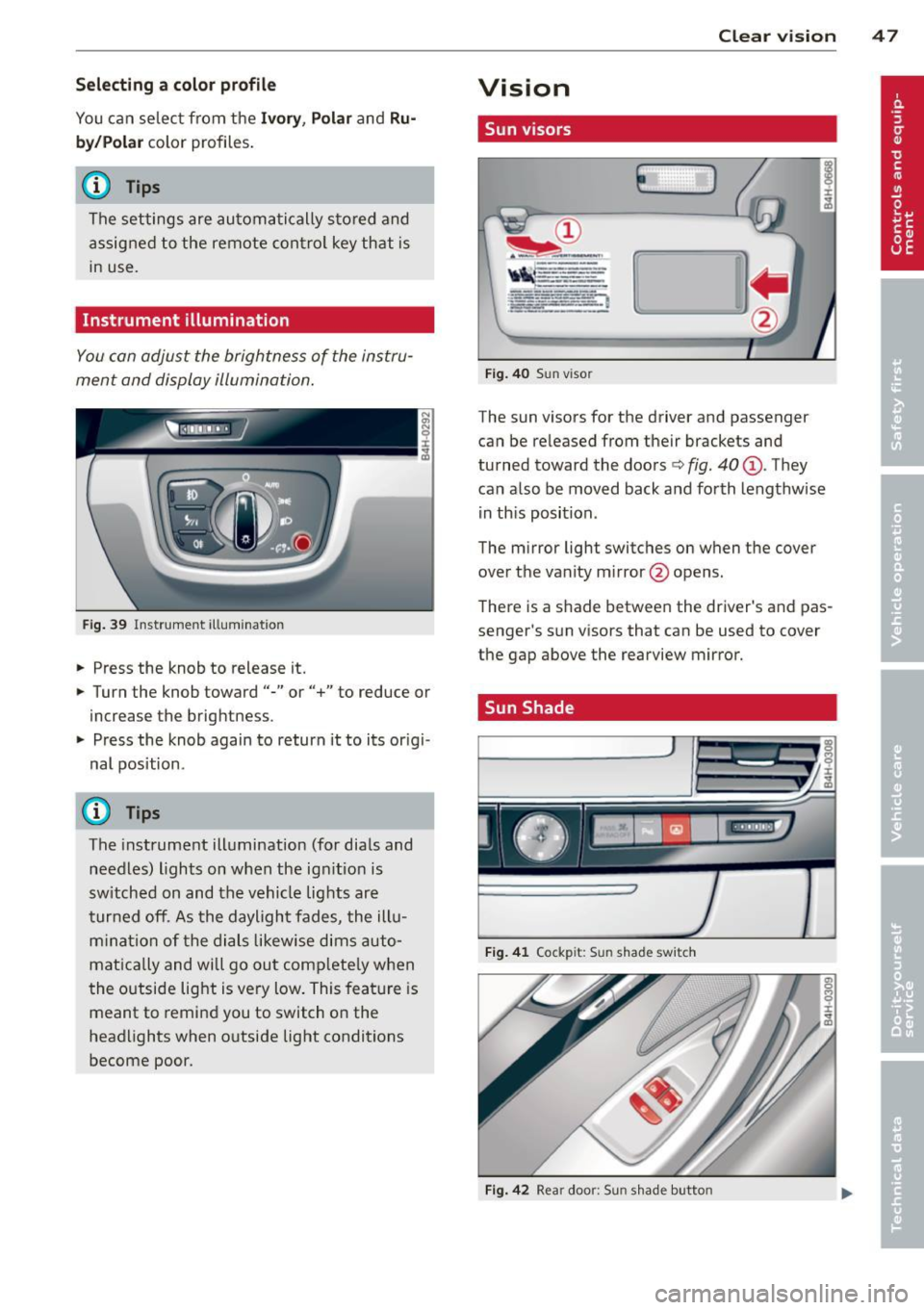
Instrument illumination
You con adjust the brightness of the instru
ment and display illumination .
Fig . 39 In strument ill um ination
• Press the knob to release it.
• Turn the knob toward"-" or"+" to reduce or
increase the brigh tness .
• Press the knob again to return it to its or igi
nal position .
Q Tips
The instrument illumination (for dials and
needles) lights on when the ig nitio n is
sw itched on and the vehicle lig hts are
turned off. As the daylight fades, the ill u
m ina tion of the dials likewise dims auto
mat ica lly and will go out com plete ly when
t he o utside light is very low . This fea ture is
meant to remind you to switch on the
headlights when o utside light conditions
become poor. Clear vi
sion 4 7
Vision
Sun visors
E J
Fig . 4 0 Sun viso r
The sun visors for the driver and passenger
can be re leased from their bracke ts and
turned toward the doors
c:> fig. 40 (D . They
can a lso be moved back and forth lengthwise
in th is position .
The m irror light switches on when the cover
over the vanity m irror @opens.
T here is a shade between the dr iver 's and pas
senge r's s un visors that can be used to cover
the gap above the rearview mirror.
. Sun Shade
Fi g. 41 Cock pit: Sun shad e swit c h
Fig. 4 2 Rear doo r: S un s had e butto n
Page 55 of 300
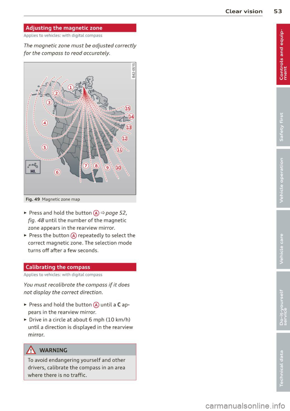
Adjusting the magnetic zone
Applies to vehicles: with digital compass
The magnetic zone must be adjusted correctly
for the compass to read accurately .
Fig. 49 Magnet ic zo ne map
.,.. Press and ho ld the button @ ¢page 52,
fig. 48
until the number of the magnetic
zone appears in the rearview mirror .
.,.. Press the but to n @ repeated ly to select the
correc t magnetic zone. The selectio n mode
turns off after a few seconds .
Calibrating the compass
Applies to vehicles: with digital compass
You must recalibrate the compass if i t does
not display the correct direction .
.,.. Press and ho ld the button @unti l a C ap·
pears in the rearview mi rror .
.,.. Drive in a circle at abou t 6 mph (1 0 km/h)
u ntil a direction is disp layed in the rearview
mir ror.
A WARNING
To avoid endangering yourself and other
drivers, calibrate the compass in an area
w here there is no traff ic.
Clear vi sion 5 3
Page 58 of 300
56 Seats and storage
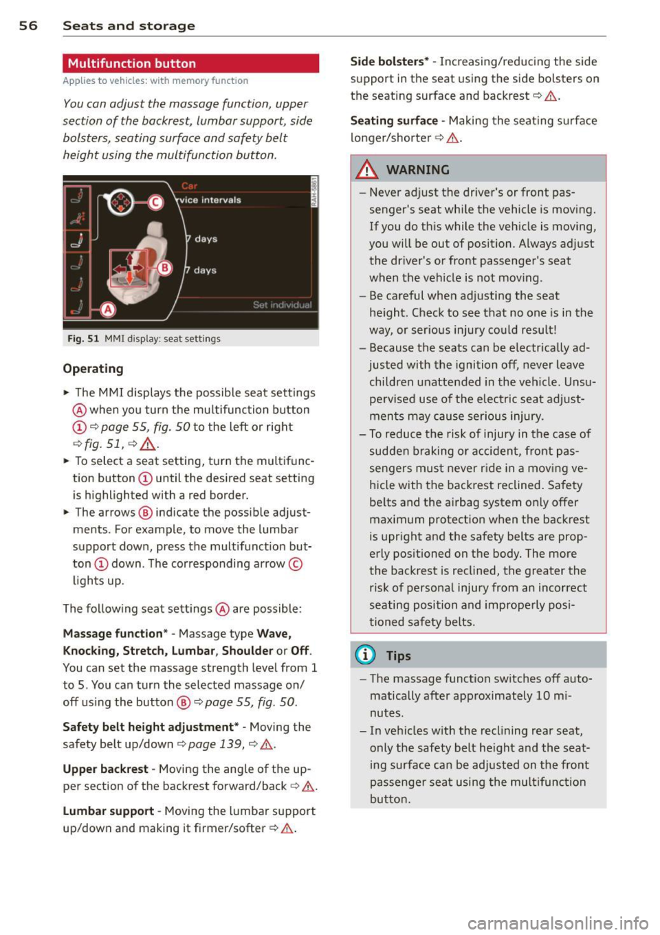
Multifunction button
App lies to vehicles: wit h memory fu nctio n
You can adjust the massage function, upper
section of the backrest, lumbar support, side
bolsters, seating surface and safety belt
height using the multifunction button.
F ig. 51 MMI display : seat settings
Operating
• The M MI displays the possible seat settings
@ when yo u turn the mu ltifunction button
c:> fig. 51, c:> .&_.
• To select a seat setting, turn the multifunc
tion button
• The arrows @ indicate the possible adjust
ments . For example, to move the lumbar
support down, press the multifunct ion but
ton
The following seat settings @are possible:
Mas sage funct ion * -Massage type Wave,
K nock in g, Stretch, Lumbar , Sho ulder or Off .
You can set the massage strength level from 1
to 5 . You can turn the selected massage on/
off us ing the button @
c:> page 55, fig. 50 .
Safety belt h eight adju stment * -Moving the
safety belt up/down
c:> page 139, c:> .&..
Upper backre st -Moving the ang le of the up
per section of the backrest forward/back
c:> &.
Lu mb ar support -Moving the lumbar support
up/down and making it firme r/softer
c:> .&. .
Side bol ster s* -Increasing/reducing the side
support in the seat using the side bolsters on
the seating surface and backrest
c:> &.
Seat ing surfa ce -Making the seat ing s urface
longer/shorter
c:> A .
A WARNING
-
-Never ad just the driver's or front pas
senger's seat whi le the vehicle is moving.
If you do this while the vehicle is moving,
you will be out of position. A lways adjust
the dr iver's or front passenge r's seat
when the vehicle is not mov ing.
- Be careful when adjusting the seat
he ight . Check to see that no one is in the
way, or serious injury cou ld result!
- Because the seats can be electrically ad
justed with the ignition off, never leave
children unattended in the veh icle. Unsu
perv ised use of the e lectr ic sea t adj ust
men ts may cause serious injury.
- To reduce the risk of injury in the case of
sudden b raking or acc iden t, front pas
sengers mus t
never ride in a movi ng ve
hicle with the backrest reclined . Safety
be lts and the airbag system only offer
maximum protection when the backrest
is upright and the safety belts are prop
erly positioned on the body . The more
the backrest is reclined, the greater the risk of personal injury from an incorrect
seating position and improperly pos i
tioned safety belts .
@ Tips
-The massage function switches off auto
matically after approximately 10 mi
nutes.
- In vehicles w ith the reclining rear seat,
only the safety belt he ight and the seat
ing surface can be adjusted on the front
passenge r sea t using the mul tifunc tion
butto n.
Page 61 of 300
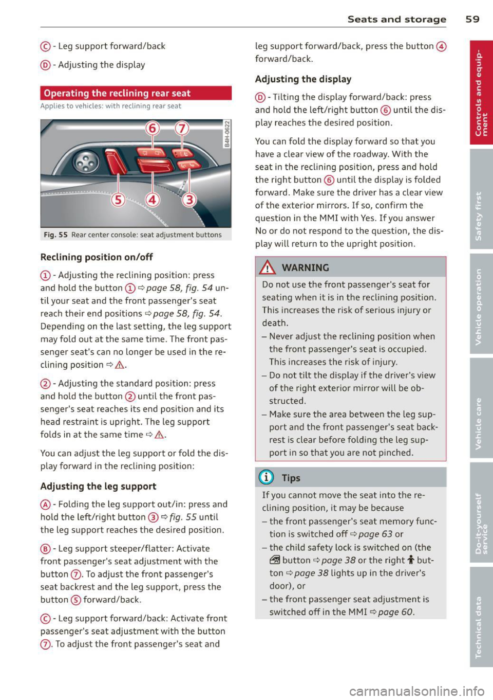
©-Leg support forward/back
@ -Adjusting the display
Operating the reclining rear seat
Ap plies to vehicles : wit h recl in ing rea r seat
Fig. 55 Rear ce nter console : seat adjustment buttons
R eclining po sition on /off
@ -Adjusting the reclining position: press
and hold the button@c:>
page 58, fig . 54 un
til your seat and the front passenger's seat
reach their end pos itions ¢
page 58, fig. 54.
Depending on the last setting, the leg support
may fold out at the same time. The front pas
senger seat 's can no longer be used in the re
clining position
¢ & .
@ -Adjusting the standard position: press
and hold the button @ unt il the front pas
senger's seat reaches its end position and its
head restra int is upr ight . The leg s upport
folds in at the same time
¢ .&, .
You can adjust the leg support or fold the dis
p lay forward in the reclining position:
Adju sting th e leg support
@ -Folding the leg support out/in: press and
hold the left/right button@¢
fig. 55 unt il
the leg support reaches the des ired posit ion .
@ -Leg support steeper/flatter: Activate
front passenger's seat adjustment with the
button
(Z) . To adjust the front passenger's
seat backrest and the leg support, press the button ®forwa rd/back.
© -Leg support forward/back: Activate front
passenger's seat adjustment w ith the button
Sea ts a nd s to rage 59
leg support fo rward/back, p ress the button @
forward/back.
Adju sting the d ispl ay
@ -Tilting the display forward/back: press
and hold the left/right b utton @ unti l the d is
play reaches the desired position.
You can fold the display forward so that you have a clear view of the roadway. With the
seat in the recl ining posit ion, press and hold
the right button @ unti l the display is folded
forward . Make sure the driver has a clear view
of the exterior mirrors. If so, confirm the
question in the MMI with Yes. If you answer
No or do not respond to the question, the dis
play will return to the upright position.
.&_ WARNING
Do not use the front passenger 's seat for
seating when it is in the reclin ing pos ition .
This increases the risk of serious injury or
death.
- Never adjust the recl ining posit ion when
the front passenger's seat is occupied.
This inc reases the r isk of injury.
- Do not t ilt the display if the driver's view
of the right exter io r mirro r will be ob
s truc ted .
- Ma ke sure the a rea between the leg sup
port and the front passenger's seat back
rest is clear before fo lding the leg sup
port in so that you are not pinched.
(D Tips
If you cannot move the seat into the re
clin ing position, it may be because
- the front passenger's seat memory func
tion is switched off c:>
page 63 or
- the ch ild safety lock is switched on (the
~ button c:> page 38 or the right t but
t on¢
page 38 lights up in the dr iver's
door), o r
- t he front passe nger seat adjustment is
switched off in the MM I c:>
page 60.
Page 78 of 300

76 Warm and cold
Operation
We recommend pressing the IAU TOI button and setting the temperature to 72 °F (22 °C) .
Fig. 77 Cockp it co ntrols
F ig . 78 fou r zone automat ic cl imate co ntrol: rea r con
trols
Press the buttons to t urn the f unctions on or
off . Use the d ials to adjust the temperature,
the blower speed and the air distribution . The
LED in a button will light up when the func
tion is sw itched on. The settings are show n in
the cl imate co ntrol d isplay a nd are also shown
in the MMI display for a few seconds . The driv
er and front passenger settings ca n be ad just
ing separately.
You can a lso adjust the rear left and r ight
sides in the fo ur zone automat ic climate co n
trol* ~
fig. 78.
IO FF ! Switching the clim ate control
system on/off
The IO FFI b utton switches the climate control
system on or off . It a lso switches on when you
turn the dia l or press any b utton . Airf low from outside is blocked when the c
limate control
system is switched off .
You can a ctivate the residual hea t fu nction
when the ignition is off by p ressing and hold
i ng the ~ button . The residua l heat from the
coolant is used to heat the vehicle interior.
The residua l heat function switches off a uto
matically after about 30 minutes.
IACI Switching cooling mode on /off
T he air is not coo led and h umidity is not re
moved when cooling mode is switched off.
T his can ca use fog on the windows. Cooling
mode switches off automatically when the
outside temperature is below zero.
1 -1 Switching reci rculation mode on /off
In recircu lation mode, the air inside the vehi
cle is c irculated and f iltered. This prevents the
u nfiltered air outs ide the vehicle from enter
ing the vehicle interior . We recommend
switching recircu lation mode on when driving
t h rough a tunne l or when s itting in traff ic
q &_ .
The !AU TO I button or~ button switches reci r
cu lation mode off.
IAU TOI Switching automatic mode on
A utomat ic mode maintains a cons tant tem
perature inside the vehicle. A ir temperature,
IJli>