center console AUDI A8 2013 User Guide
[x] Cancel search | Manufacturer: AUDI, Model Year: 2013, Model line: A8, Model: AUDI A8 2013Pages: 318, PDF Size: 79.34 MB
Page 72 of 318
70 Seats and storage
Pass-through with ski
sack
Preparing the pass-through
Appl ies to vehicles: with pass-through and ski sack
Long objects such as skis con be transported
in the ski sock.
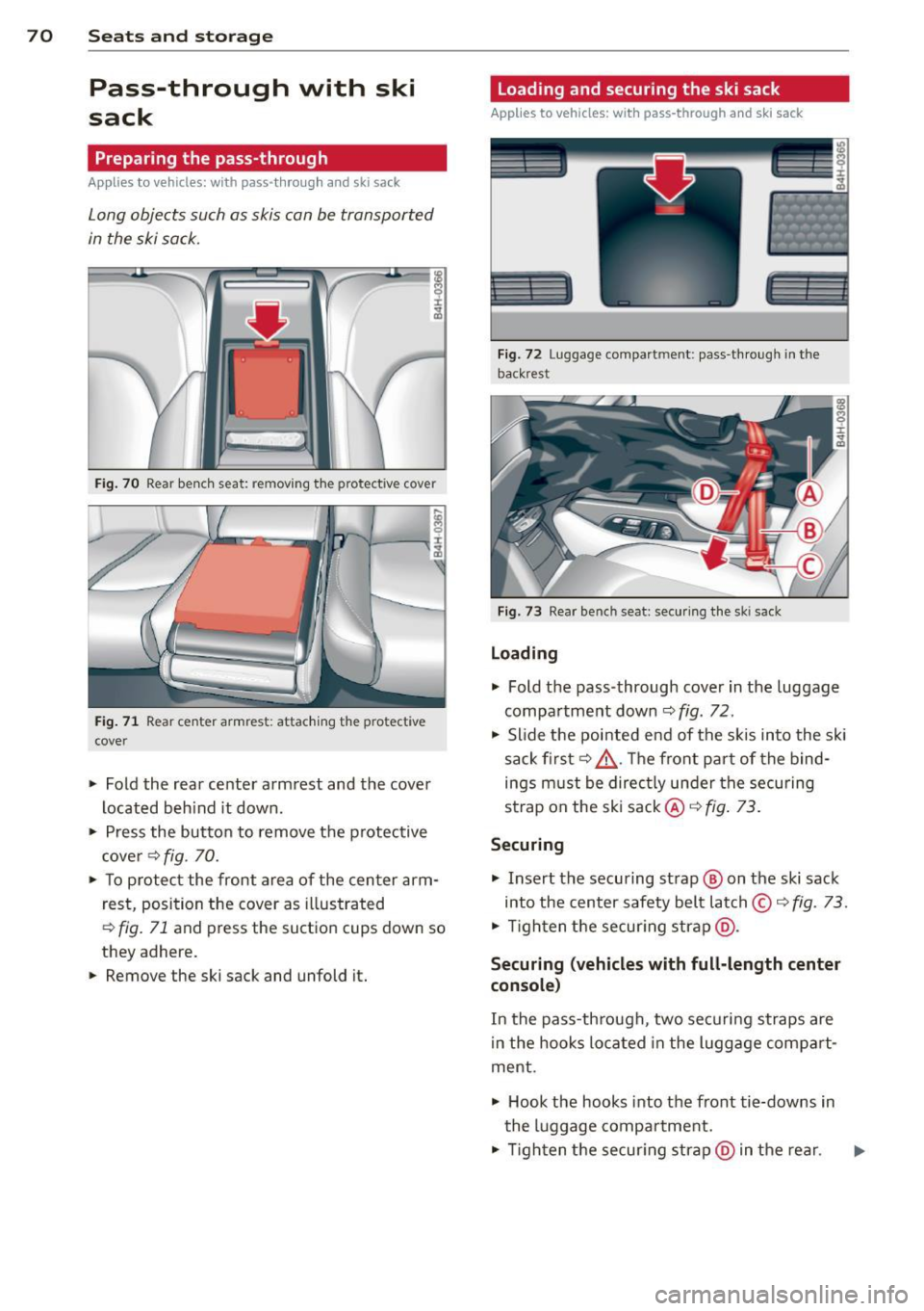
Fig. 70 Rear benc h seat: removing t he protective cover
Fig . 71 Rear center armres t: attaching the protective
cover
.. Fold the rear center arm rest and the cover
located beh ind it down .
.,. Press the butto n to remove the p rotective
c ove r¢
fig . 70.
.. To p rotect the front area of the center arm
r est, position the cover as illustrated
,::;, fig. 71 and press the suct io n cups down so
they adhere.
.. Remove the ski sack and unfold it.
Loading and securing the ski sack
Applies to vehicles: with pass -through and ski sack
--~ --
--· ---
Fig. 72 Luggage compartmen t: pass -th roug h in th e
back rest
F ig. 73 Rear bench seat: secu ring the sk i sack
Loading
.,. Fold the pass-through cover in the luggage
compa rtment down ¢
fig. 72.
.,. Slide the pointed end of the s kis into the sk i
sack first¢ &. The front par t of the bind
ings must be direc tly under the securing
strap on the ski sack@¢
fig. 73.
Securing
.,. Insert the securing strap@ on the ski sack
into the center safety belt latch © ¢
fig. 73 .
.,. Tigh ten t he secur ing strap @.
Securing (vehicles with full-length center
console )
In the pass-th rough, two securi ng straps are
i n the hooks lo cated in the lugg age compa rt·
ment .
.,. Hook the hooks into the front tie-downs in
the luggage compartment .
.,. Tigh ten the secur ing str ap @ in the rear .
Page 75 of 318
-Never exceed the maximum permissible
load carry ing capacity of the roof of your
vehicle, the permissible axle weights and
the permissible total weight of your vehi cle
~ page 290, Weights.
@ For the sake of the environment
As a result of the increased wind resistance created by a roof rack, your vehicle is
using fue l unnecessarily. So remove the
roof rack after using it.
12-volt sockets
Applies to vehicles: 12-volt sockets
Electrical accessories can be connected to ev
ery 12-volt socket.
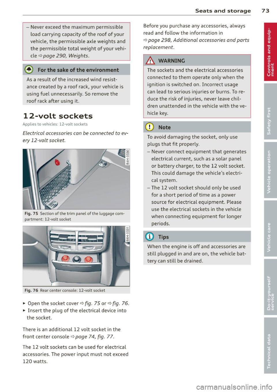
Fig. 75 Section of the trim panel of the luggage com
part men t; 12-volt socket
Fig. 76 Rear center console: 12-volt socket
"' Open the socket cover¢ fig. 75 or¢ fig. 76.
"' Insert the plug of the e lectrical device into
the socket.
There is an additional 12 volt socket in the
front center console¢
page 74, fig. 77.
The 12 volt sockets can be used for electrical
accessories. The power input must not exceed
120 watts.
Seats and storage 73
Before you purchase any accessories, always
read and follow the information in
~ page 298, Additional accessories and parts
replacement.
A WARNING
The sockets and the electrical accessories
connected to them operate only when the ignition is switched on. Incorrect usage
can lead to ser ious injuries or burns. To re
duce the risk of injuries, never leave chil
dren unattended in the vehicle with the ve
hicle key.
(D Note
To avoid damaging the socket, only use
plugs that fit properly.
- Never connect equipment that generates
electrical current, such as a solar pane l
or battery charger, to the 12 volt socket.
This could damage the vehicle's electri
cal system .
- The 12 volt socket should only be used
for a short period of ti me as a power
source for electrical equ ipment . Please
use the electrical sockets in the vehicle
when connecting equipment for longer periods.
(D Tips
When the engine is off and accessories are
still plugged in and are on, the vehicle bat
tery can still be drained.
Page 76 of 318
7 4 Seats and storage
Storage
(upholder
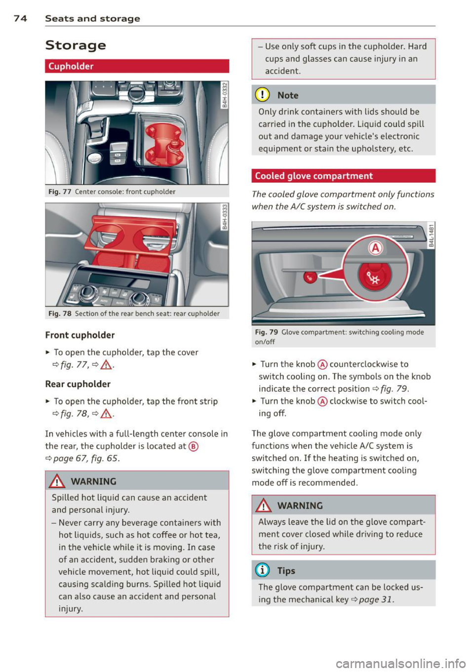
Fig . 77 Center conso le: front cupholder
Fig. 78 Section of the rear bench seat: rear cupholder
Fr ont cuphold er
., To open the cupholder, tap the cover
¢ fig. 77, ¢ &_ .
Rear cupholder
., To open the cupholder, tap the front strip
¢ fig. 1a, ¢ A .
In vehicles with a full-length center console in
the rear, the cupholder is located at @
¢ page 67, fig. 65.
A WARNING
Spilled hot liquid can cause an accident
and personal inj ury .
- Never car ry any beverage containers wi th
hot liquids, s uch as hot coffee or hot tea,
in the veh icle while it is mov ing. In case
of an accident, sudden braking or other
vehicle movement, hot liqu id could spill,
causing scalding burns. Spi lled hot liquid
can also cause an accident and personal injury. -
Use on ly soft cups in the cupholder. Hard
cups and glasses can cause injury in an
accident.
(D Note
Only drink containers with lids should be
carried in the cupholder. Liquid could spill
out and damage your vehicle's electronic
equipment or stain the upholstery, etc.
Cooled glove compartment
The cooled glove compartment only functions
when the AIC system is switched on.
Fig. 79 Glove compartme nt: sw itching cool ing mode
on/off
., Turn the knob @counterclockwise to
sw itch cooling on . The symbols on the knob
indicate the correct position¢
fig. 79 .
., Turn the knob @clockwise to switch cool·
ing off.
The glove compartment cooling mode only
funct ions when the vehicle A/C system is
switched on. If the heat ing is sw itched on,
switching the glove compa rtment cooling
mode off is recommended.
A WARNING
A lways leave the lid on the glove compa rt
ment cove r closed while dr iving to reduce
t he r isk o f injury.
(1) Tips
The glove compartment can be Locked us·
i ng the mechanical key
¢page 31.
Page 77 of 318
Additional storage
There are a variety of storage compartments
and fasteners in various places in the vehicle.
- Storage compartments in the doors
- Net in the front passenger footwell
- Eyeglasses compartment in the headliner (near the rearview mirror)
- Storage compartments under the center
armrests
- Compartments* on the back of the front
seat backrests
- Garment hooks over the rear doors
- Compartment in the center console with
pass-through)* (rear)
- Compartment behind the rear center arm
rest (in vehicles without the pass-through*
or refrigerator*)
- Bag hooks in the luggage compartment
A WARNING
-When driving, do not leave any hard ob
jects on the rear window shelf or allow
your pet to s it on the shelf. They could
become a hazard for veh icle occupants in
the event of sudden brak ing or a crash.
- Always remove objects from the instru
ment panel. Any items not stored could
slide around inside the vehicle while driv
ing or when accelerating or when apply
ing the brakes or when driv ing around a
co rner.
- When you are driving make sure that
anything you may have placed in the cen
ter console o r othe r storage lo cat ions
cannot f all out in to the footwells. In case
of sudden braking you would not be able
to brake or acce lerate .
- Any articles of clothing that you have
hung up must not interfere with the driv
er's view . The coat hooks are designed
only for lightweight clothing. Never hang
any clothing w ith hard, pointed or heavy
objects in the pockets on the coat hooks.
During sudden braking or in an accident -
especially if the airbag is deployed -
Seat s an d sto rage 75
these objects co uld inj ure any passen
gers ins ide the vehicle.
- To reduce the risk of persona l injury in an
accident or sudden stop, a lways keep the
glove compartment closed wh ile driving.
- Read and follow a ll WARNINGS
¢ page 172, Important safety instruc
tions on the side airbag system.
- Hang clothes in such a way that they do
not impair the driver's vision.
- The coat hooks must only be used for
lightweight clothing. Do not leave any
heavy or sharp edged objects in the pock
ets which may interfere with the s ide cur
tain airbag deployme nt and can cause
pe rsonal injury in a crash .
- Do not use coat hangers for hanging cloth ing on the coat hooks as t his can in
terfere with proper deployment of the
side curta in a irbags in an acc ident.
- Do not hang heavy objects on the coat
hooks, as they could cause perso nal in
jury in a sudden stop.
(D Note
Objects located on the rear shelf that rub
against the rea r window could damage the
heating wires for the rear window defog
ger.
@ Tips
- A vent slot is located between the shelf
and the rear w indow. Do not bloc k the
vent with any items you may place o n the
rear window she lf.
- Do not place bu lky i tems o n the rear win
dow shelf as they could res tri ct or bloc k
t he drive r's vision in the rear view m irror.
Cooler
Introduction
App lies to vehicles : wi th coo ler
Please clean the cooler before using it for the
first time
¢ page 226.
You can only sw itch on the coo ler if
Page 82 of 318
80 Warm and cold
airflow and air distribution are controlled au
tomatically.
Adjusting the temperature
Temperatures between 60 °F (+16 °() and
84
°F (+28 °C) can be set. Outside of this
range,
lo or hi will appear in the climate con
trol system display. At both of these settings,
the climate control system runs continuously
at maximum cooling or heating power. There
is no temperature regulation.
~ Adjusting the airflow
You can adjust the airflow manually to suit
your needs. To have the airflow regulated au
tomatically, press the
! AUTO ! button.
~ Adjusting the air distribution
You can manually select the vents where the
air will flow. To have the air distribution regu
lated automatically, press the
IAUTOI button.
~ I lil* Adjusting Seat heating/
ventilation*
Pressing the button switches the seat heat
ing/ventilation on at the highest setting (level
3). The L EDs indicate the temperature level.
To reduce the temperature, press the button
again. To switch the seat heating/ventilation
off, press the button repeatedly until the LED
turns off.
After 10 minutes, the seat heating/ventilation
automatically switches from level 3 to level 2.
In vehicles without the four zone automatic
climate control*, buttons in the rear center
console control the seat heating for both out
er rear seats*.
~ Switch the defroster on/off
The windshield and side windows are defrost
ed or cleared of condensation as quickly as
possible. The maximum amount of air flows
mainly from the vents below the windshield.
Recirculation mode switches off. The tempera
ture is controlled automatically.
The
IAUTOI button switches the defroster off.
~ Switching rear window heater on/off
The rear window heater only operates when
the engine is running. It switches off auto
matically after 10 to 20 minutes, depending
on the outside temperature.
To prevent the rear window heater from
switching off automatically , press and hold
the~ button for more than 2 seconds. This
r ema ins stored until the ignition is switched
off.
I SYNC I Synchronization*
When synchronization is switched on, the set
tings for the driver's side are applied to the
front passenger's side (except for seat heat
ing/ventilation*). The rear seat is also
synchronized in vehicles with the 4-zone de
luxe automatic climate control system*. Syn
chronization switches off if the settings are
adjusted on the front passenger's side or in
the rear*.
You can synchronize the settings in a row by
pressing and holding a knob. For example, to
apply the settings for the front passenger's side to the driver's side, press and hold the
knob on the front passenger's side.
Air vents
You can open or close the center and rear
vents in the cockpit and the vents in the rear
center console and door pillars using the
ridged thumbwheels. The levers adjust the di
rection of the airflow from the vents.
,&. WARNING
- Do not use the recirculation mode for ex
tended periods of time. The windows
could fog up since no fresh air can enter
the vehicle. If the windows fog up, press
the air recirculation button again imme
diately to switch off the air recirculation
function or select defrost.
- Individuals with reduced sensitivity to
pain or temperature could develop burns
when using the seat heating function. To reduce the risk of injury, these individu-
als should not use seat heating . .,..
Page 85 of 318

the stored position as soon as you switch on
the ignition.
Starting and stopping
the engine
Starting the engine
This button switches on the ignition and
starts the engine.
Fig. 85 Center console: S TART ENGINE S TOP b utton
Switching the ignition on/off
• To switch the ignition on/off, press the
I START ENGINE STOPI button. Do not press
the brake pedal while doing this.
Starting the engine
• Press the brake pedal QA .
• Press the !START ENGINE STOPI button
Q fig . 85. The engine will start.
If the engine does not start immediately, the
starting process is automatically stopped af
ter a short time. Repeat starting procedure.
Start-Stop-System*:
When you stop and the Start -Stop -System*
turns off the engine, the ignition still remains
switched on.
- If you press the !S TART ENGINE STOPI but
ton now, the ignition will be switched off.
The engine will not start
¢page 89.
- Make sure that the ignit ion is switched off
before exiting the vehicle.
Switching the ignition/engine off
automatically*
The follow ing applies to vehicles with Start
Stop-System*: to prevent the battery from
On the road 83
draining, the ignition and the engine will
switch off automatically under the following
cond itions:
- The vehicle has already been driven.
- The driver's door is opened.
- The driver's seat belt is removed .
- The brake pedal is not pressed down.
- The vehicle is stationary.
In this case, the activated low beam will be re
placed by the side marker lights. The side
marker lights will switch off after a certain pe
riod of time or when you lock the vehicle .
A WARNING
-Never allow the engine to run in conf ined
spaces -danger of asphyx iation.
- Never turn off the engine until the vehi
cle has come to a complete stop.
- The brake booster and power steering
only work when the engine is running. If
the engine is off, you have to use more
force when steering or braking. Because
you cannot steer and brake as you usual
ly would, this could lead to crashes and
serio us injuries.
(D Note
- Avo id h igh engine rpm, full throttle and
heavy engine loads until the engine has
reached operating temperature - other
w ise you risk engine damage.
- The engine cannot be started by pushing
or towing the vehicle.
@ Tips
-After a co ld engine is started, there may
be a brief period of inc reased noise be
cause oil pressure must first build up in
the hydraulic valve adjusters. This is nor
ma l and not a cause for concern.
-If you leave the vehicle with the ignition
switched on, the ignition w ill switch off
after a certain period of time. Please
note that electrical equipment such as
exterior lights will sw itch off as well
when that happens.
Page 91 of 318

@ Tips
When you stop and the start-stop-system
turns the engine off, the ignition remains on. Make sure that the ign ition is switched
off before exiting the vehicle.
General information
App lies to vehicles: with Start-Stop-System
The standard Start-Stop-mode can be cancel·
led for different system-related reasons.
Fig. 89 Instrument cluster : eng ine-Stop temporar ily
u navailable
Engine will not switch off
Before each stop phase, the system checks if
certain cond itions have been met . For exam
p le, the engine will
not be switched off in the
following situations:
- The engine has not reached the minimum
required temperature for Start -Stop-mode .
- The interio r temperature selected by the A/C
system has not been reached.
- Th e outside temperature is extremely h igh/
low.
- The windshield is being defrosted
9page 81.
- The parking system* is switched on.
- The battery charge level is too low .
- The steering wheel is sharply turned or there is a steer ing movement.
- After engaging the reverse gear.
- On sharp inclines .
The
(jj indicator light appears in the informa
tion line in the instrument cluster display
9fig. 89.
On the road 89
Engine automatically restarts
The stop phase is interrupted in the following
situations, for example. The engine restarts
without any action by the driver.
- The interior temperature varies from the
temperature selected in the A/C system.
- The windsh ield is being defrosted
9page 81.
-The brake pedal is pressed severa l times in a
row.
- The battery charge level becomes too low .
- High power consumpt ion.
@ Tips
If you shift into the D, Nor S positions af
ter sh ifting into
reverse, the vehicle must
be driven faster than 6 mph (10 km/h) in
order for the engine to sw itch off aga in.
Switching the Start-Stop-System on/off
manually
App lies to vehicles: wi th Start-Stop-Sys te m
If you do not wish to use the system, you can
switch it off manually.
Fig. 90 Center console: Start-Stop-System button
.,. To switch the Start-Stop-System off/on
manually, press the
l "'I button. The LED in
the button turns on when the system is
sw itched off.
@ Tips
If you switch the system off during a stop
phase, the engine will start again auto
matically.
Page 126 of 318
124 Park in g sy ste m s
Switching on /off
Appl ies to vehicles: with advanced parking system wit h
rear view camera
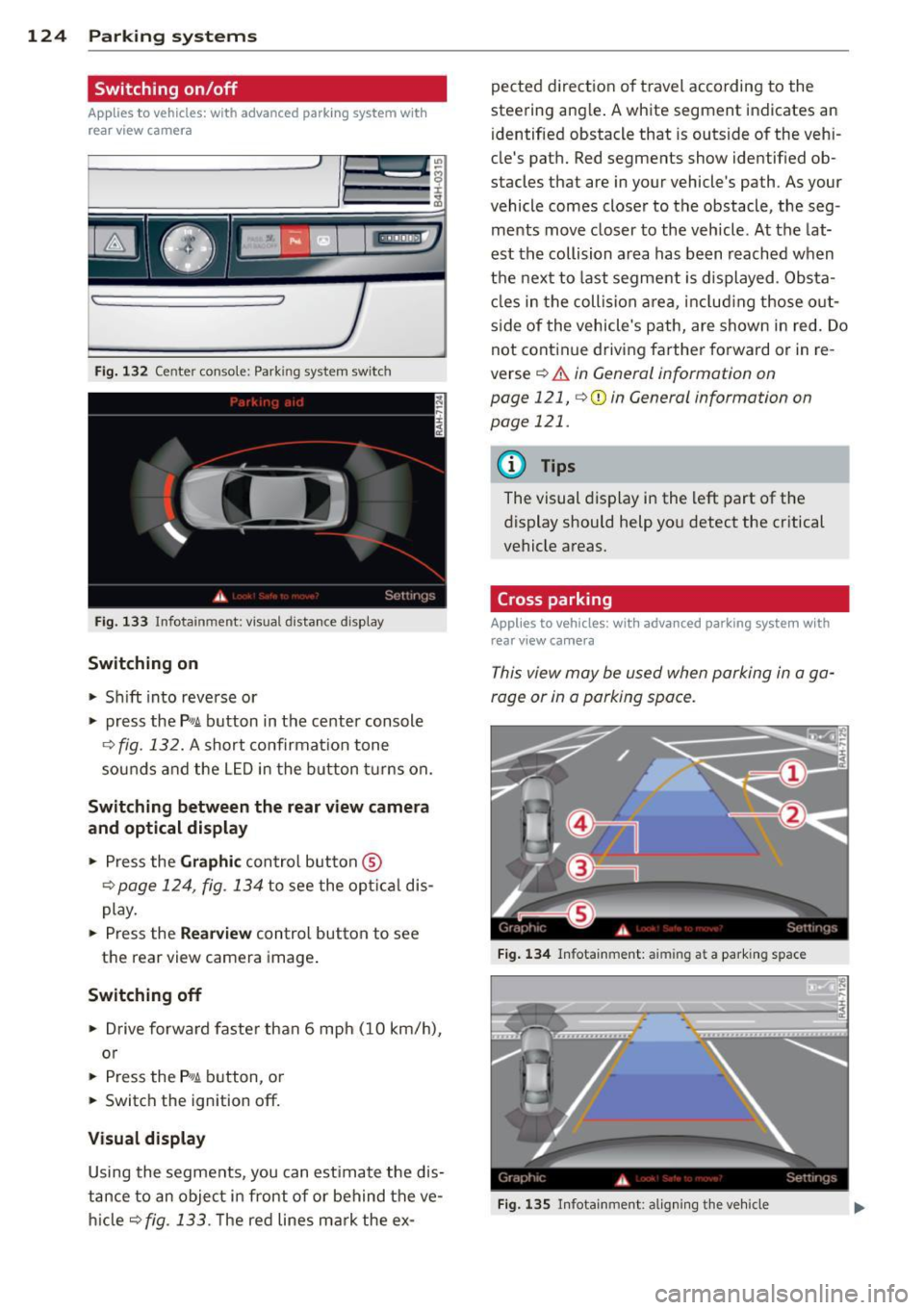
Fig. 132 Center console: Park ing system switch
Fig. 133 Infota inment: visual distance d isplay
Switching on
.. Shift into reverse or
.. press the
P,#A button in the center console
¢ fig. 132. A short confirmat ion tone
sounds a nd the L ED in the button t urns on.
Sw itching between the rear view camer a
and optical displa y
.. Press the Graphic control button ®
¢ page 124, fig. 134 to see the opt ical dis
play .
.. Press the
Rearv ie w control button to see
the rear view camera image .
Switching off
.. Drive forwa rd faster than 6 mph (10 km/h),
o r
.. Press the
P'#A b utton, o r
.. Switch the ignition off.
Visual displa y
Using the segments, you can estimate the dis
tance to an object in front of or behind the ve
h icle
¢fig .133. T he red lines mark the ex-pected direction of t
ravel according to the
steering ang le . A white segment indicates an
identified obstacle that is outside of the vehi
cle's path. Red segments show identified ob
stacles that are in your vehicle's path. As your
vehicle comes closer to the obstacle, the seg
ments move closer to the vehicle. At the lat
est the collision area has been reached when
the next to last segment is displayed . Obsta
cles in the collision area , includ ing those out
s ide of the vehicle's path, are shown in red. Do
not cont inue driving farther forward or in re
verse
¢ .&. in General information on
page 121,
¢ 0 in General information on
page 121.
(D Tips
The visual display in the left part of the
display should help you detect the critical
vehicle areas.
Cross parking
Applies to vehicles: with advanced parking system with
rear view ca mera
This view may be used when parking in a ga
rage or in a parking space .
Fig . 1 34 Infota inment: aimi ng a t a parking space
Fig. 135 Infotainment: aligning th e ve hicle
Page 129 of 318
your outside mirror or a corner of your
vehicle does not collide with any obsta
cles.
@ Tips
If the 8/cr;sJ/c:::::5, symbol appears in the
disp lay and the respect ive display area is
grayed out, then the power exter ior mir
rors were fo lded in or the dr iver's door/
front passenger's door/luggage compart ment lid was opened .
Switching on or off
Applies to vehicles: with top view camera system
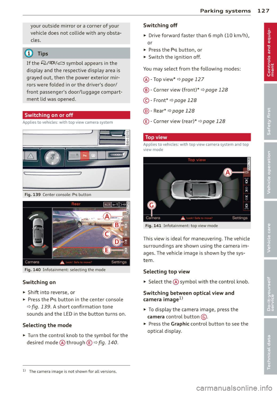
Fig. 139 Center console: P.,.1,_ button
Fig. 14 0 Infotainment : se lect ing t he mode
Switching on
.. Sh ift into reve rse, or
.. Press the P
10A button in t he center console
r::!v fig. 139 . A short confirmat ion tone
sounds and the LED in the button turns on .
Selecting the mode
.. Turn the contro l knob to the symbol for the
desired mode @th ro ugh
© co fig. 140 .
11 The ca mera image is not show n fo r al l versions.
P arking systems 12 7
Switching off
.. Drive fo rward fas ter than 6 mph (10 km/h),
or
.. Press the
PwA button, or
.. Switch the ignit ion off .
You may select from the following modes:
@ -Top view*¢
page 127
® -Corner view (front)*¢ page 128
©-Front* co page 128
@-Rear* ¢ page 128
©-Corner view (rea r)* co page 128
Top view
App lies to veh icles: w ith top v iew camera system and top
v iew mode
Fig . 141 In fotainment: top view mode
T his view is ideal for maneuvering. The ve hicle
s u rroun din gs are shown usi ng the came ra im
ages . The veh icle im age is shown by the sys
tem.
Selecting top view
.. Select the @symbo l with the control knob .
Switching between optical view and
camera image
1 )
.. To display the came ra image, press the
camera control button @ .
.. Pres s th e
Graphi c control button to see the
optical d isp lay .
Page 169 of 318
and safety belts with pretensioners are
scrapped, all applicable laws and regula
tions must be observed. Your authorized
Audi dealer is familiar with these require
ments and we recommend that you have
your dealer perform this service for you .
Other things that can affect Advanced
Airbag performance
Changing the vehicle's suspension system can
change the way that the Advanced Airbag Sys
tem performs in a crash. For example, using
tire-rim combinations not approved by Audi,
lowering the vehicle, changing the stiffness of
the suspension, including the springs, suspen
sion struts, shock absorbers etc. can change
the forces that are measured by the airbag
sensors and sent to the electronic control
unit. Some suspension changes can, for exam ple, increase the force levels measured by the
sensors and make the airbag system deploy in
crashes in which it would not deploy if the
changes had not been made. Other kinds of
changes may reduce the force levels meas
ured by the sensors and prevent the airbag
from deploying when it should.
The sensors in the safety belt buckle for the
driver and front passenger seat tell the elec
tronic control module if the safety belt is
latched or not. If the safety belt is being used,
the front airbag will deploy at a slightly high
er rate of vehicle deceleration than if the safe
ty belt is not being used. Therefore, in a par
ticular collision, it is possible that an airbag
will not deploy at a seating position where the safety belt is being used but will inflate at the
position where the safety belt is not being
used . It is important that nothing interfere
with the safety belt buckles so that the sen
sors can send the correct information about
safety belt use to the electronic control unit.
A WARNING
Changing the vehicle's suspension includ
ing use of unapproved tire-rim combina
tions can change Advanced Airbag per-
Airbag system 167
formance and increase the risk of serious
personal injury in a crash.
- Never install suspension components
that do not have the same performance characteristics as the components originally installed on your vehicle.
- Never use tire-rim combinations that have not been approved by Audi.
A WARNING
Items stored between the safety belt buckle and the center console can cause
the sensors in the buckle to send the
wrong information to the e lectronic con
trol module and prevent the Advanced Air
bag System from working properly.
- Always make sure that nothing can inter
fere with the safety belt buckles and that
they are not obstructed.
Knee airbags
Description of knee airbags
The knee airbag system can provide supple
mental protection to properly restrained
front seat occupants.
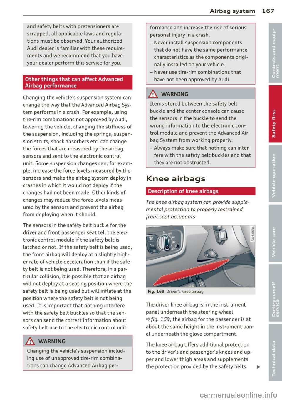
Fig . 169 Driver 's knee airbag
The driver knee airbag is in the instrument
panel underneath the steering wheel
¢ fig . 169, the airbag for the passenger is at
about the same height in the instrument pan
el underneath the glove compartment.
The knee airbag offers additional protection
to the driver 's and passenger's knees and up
per and lower thigh areas and supplements
the protection provided by the safety belts.
Ill-