light AUDI A8 2014 Owners Manual
[x] Cancel search | Manufacturer: AUDI, Model Year: 2014, Model line: A8, Model: AUDI A8 2014Pages: 314, PDF Size: 78.47 MB
Page 246 of 314
24 4 Ch eck ing and filling
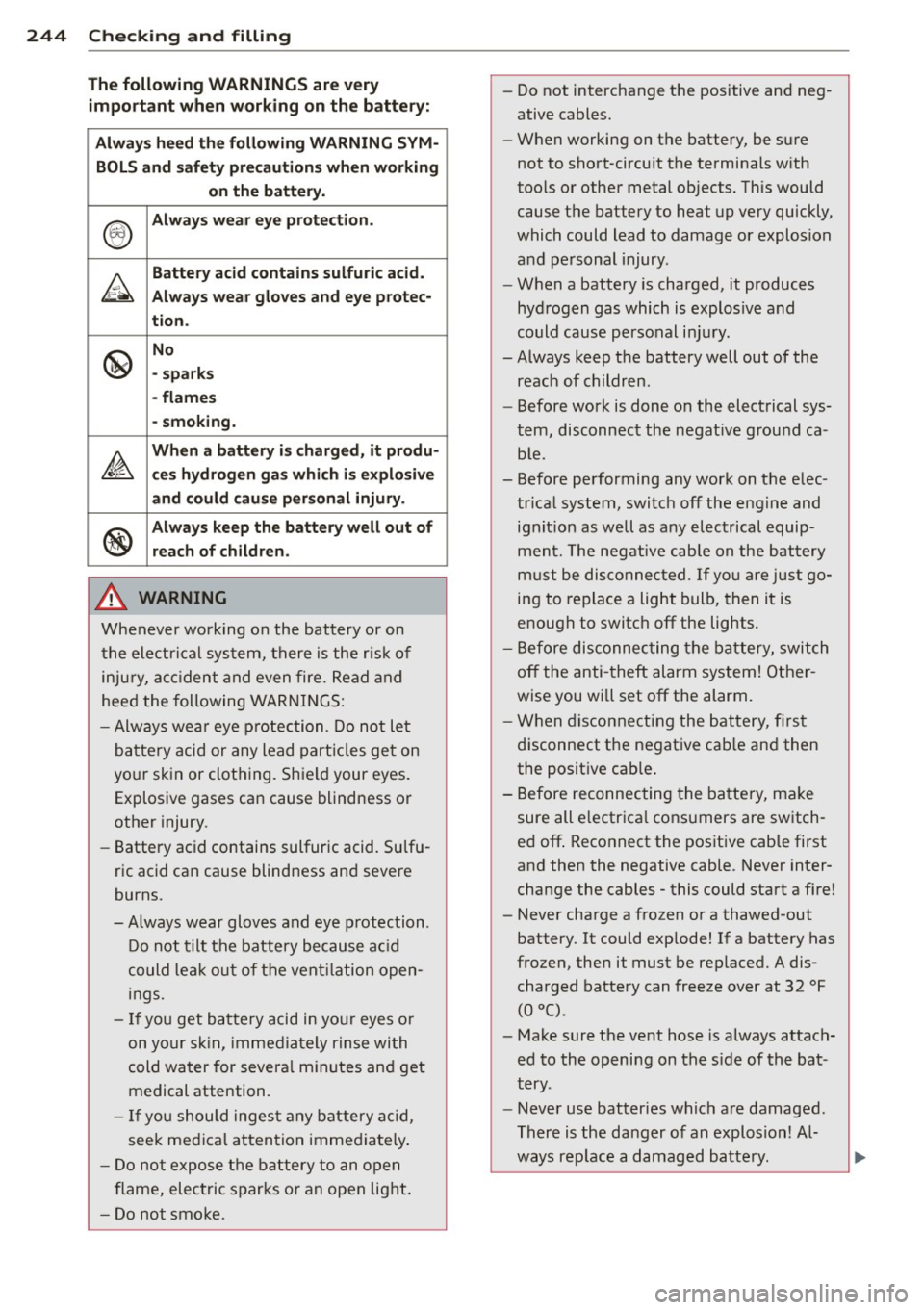
Th e following WARNINGS are v ery
impo rtant when w ork ing on the b att ery :
Alway s heed t he fo llowin g WARNING SYM ·
BOLS and s afety pr ecaution s wh en w orking
on the batter y.
®
Always wear ey e prot ection .
~
Batte ry a cid contains sulfuric acid .
Al way s w ea r glo ves and e ye prote c-
tion .
@
No
· spa rks
- fl ame s
- sm oking.
~
Wh en a batt ery is c harge d, it p rodu-
c e s hy drog en g as whi ch i s e xplo siv e
a nd c ould c ause persona l injury.
®
Alway s keep the b attery well o ut of
reach of childr en .
.8, WARNING
Whenever working on the battery or on
the electrical system, there is the r is k of
inju ry, acc ident and even fire. Read and
heed the following WARNINGS:
- Always wea r eye protection. Do not let
battery acid or any lead part icles get on
yo ur skin or clothing. Shield your eyes.
Explosive gases can cause blindness or
other injury.
- Battery acid contains sulfuric acid. Sulfu
ric acid can cause blindness and severe
burns.
- Always wear gloves and eye p rotection .
Do not tilt the battery because ac id
could lea k out of the vent ilation open
ings.
- I f you get battery acid in your eyes or
on your sk in, immediately rinse with
cold water for severa l m inutes and get
medical attention.
- If you should ingest any battery acid,
seek medical attention immediately .
- Do not expose the battery to an open
flame, electric sparks or an open light .
- Do not smoke. -
Do not interchange the positive and neg
ative cables.
- When working on the battery, be s ure
not to short-circu it the terminals with
too ls or other metal objects. This would
cause the battery to heat up very quickly,
which could lead to damage or explosion and pe rsonal injury.
- When a battery is charged, it produces
hydrogen gas which is explosive and
could cause personal in jury.
-Always keep the battery well out of the reach of children.
- Before work is done on the electrical sys
tem, disconnect the negat ive ground ca
b le.
- Before performing any work on the elec trical system, switch off the engine and
ignit ion as well as any electrical equip
ment. The negative cable on the battery
m ust be disconnected.
If yo u are just go
ing to replace a light bulb, then it is
enough to switch off the lights .
- Before disconnec ting the bat tery, switch
off the anti -theft alarm system! Other
wise you wi ll set off the alarm.
- When disconnecting the battery, f irst
disconnect the negative cab le and then
the positive cab le .
- Before reconnecting the battery, ma ke
sure all e lectr ica l consumers are sw itch
ed off . Reconnect the positive cable first
and then the negative cable. Never inter
change the cables· this could start a fire!
- Never charge a frozen or a thawed-out
battery. It could exp lode! If a battery has
frozen, then it must be replaced. A dis
charged batte ry can freeze over at 32 °F
(0 °() .
-Make sure the vent hose is always attach
ed to the opening on the s ide of the bat
tery .
- Never use batteries which are damaged.
There is the danger of an explosion! Al ways rep lace a damaged battery .
Page 249 of 314

Windshield/headlight washer container
Fig . 207 Eng ine co mpartmen t: cove r on the win dshield
w ash er flui d reservo ir
The washer flu id container is marked with the
symbol ~ on its cap
c> fig. 207, c> page 233 .
.. Before you check anyth ing in the engine
compartment ,
always read and heed all
WARNINGS c> A in Working in the engine
compartment on page 231 .
.. Lift the filler cap tongue to add washer flu
id . You can fill the container to the top .
.. Press the cap back onto the filler neck after
filling the containe r.
You can find the reservoir
capacity in the tab le
in
c> page 290 .
Clean water should be used when fill ing up. If
possible, use soft water to prevent scaling on
washer jets . Always add a glass cleaner solu
tion (with frost protection in the winter).
(D Note
Do not mix engine coolant antifreeze or
any other additives to fill up the wind
shield washer reservoir.
Checking and filling 247
Page 255 of 314
Tires an d wheel s 253
Bear in mind that the ti re press ure monitoring
system* can only monitor the tire pressures
you have stored. The system does not recog
n ize the load condit ion of your vehicle.
The effectiveness of the tire pressure monitor
ing system* will be impaired if you store nor
mal load pressures but then operate the vehi
cle at its maximum load
c;, &.
See the i llustration c;, fig. 208 for the location
of the label on driver's side B-pillar (co lor of
the actua l labe l and exact location on the ve
h icle wi ll vary slightly). Note that the
following table is accurate at
the time of going to press and is subject to
change. In the event of d iscrepancies, the tire
pressure label is located on the driver's side B
pillar always takes precedence.
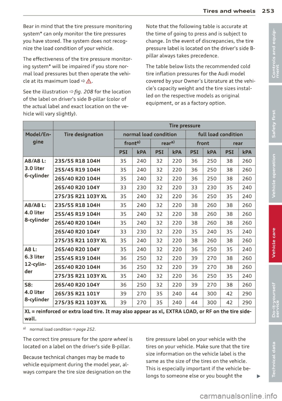
The table below lists the recommended cold
tire inflat ion pressures for the Audi mode l
covered by your Owner's Literature at the vehi
cle's capacity weight and the t ire sizes instal
led on the respective models as orig inal
equipment, or as a factory option.
Tire pressure
Model /En-
Tire design ation normal load condition
full load condition
gine fronta> reara>
front rear
PSI kPA PSI kPA PSI kPA PSI kPA
AB /AB L: 235/55 R18 104H
35 240 32 220 36 250 38 260
3 .0 lit er
255/45 R1 9 104H 35 240
32 220 36 250 38 260
6-cy lind er
26 5/40 R2 0 104H 35 240 32 220 36 250 38 260
265 /40 R20 104 V 33 230 32 220 33 230 35 240
275
/35 R 2110 3Y XL 35 240 32 220 36 250 35 240
A8/A8 L: 235 /55 R1 8 104H 35 240
32 220 38 260 38 260
4.0 l it e r
255/4 5 R19 104H 35 240 32 220 38 260 38 260
a-cy lind er
26 5/ 40 R 20 104H 35 240
32 220
38 260
38 260
2
6 5/40 R 20 104V 33 230 32 220 35 240 35 240
27
5/35 R2 110 3Y XL 35 240 32
220
38 260
38 260
AB L
: 265/40 R20 104 V 35 240 32 220 36 250 35 240
6.3 liter
255 /45 R1 9 104H 36 250 32 220
39 270
38 260
12
-cy lin-
26 5/40 R 20 104H 36 250 32 220 39 270 38 260
der
275/35 R 21 103 YXL
35 240 32 220 36 250
35 240
58
: 2 65/40 R 20 10 4V 36 250 32 220 39 270 38 260
4.0 liter
265 /35 R21101 Y 39 270 35 240 44 300 42 290
a-cy lind er
275/35 R 2110 3Y XL 39 270 35 240
44
300 42
290
XL= reinf orce d or extra lo ad tir e. It ma y als o appe ar a s x l, E XTRA LOAD, or RF on th e tire s ide-
w all .
al no rmal load co ndit ion c:> page 252.
The correct tire pressure for the spare wheel is
l ocated on a label on the dr iver's side B-pilla r.
Because technical changes may be made to
ve hicle equ ipment dur ing the model yea r, a l
ways compa re the tire size designation on the tire pressu
re label on you r vehicle with the
t ires on you r vehicle. Make sure that the t ire
size in formation on the vehicle labe l is the
same as the size of the tires on the vehicle.
This is especially important if the vehicle be-
l ongs to someone else or yo u bought the ...,
•
•
Page 257 of 314

of people and the amount of luggage into ac
count when adjusting tire pressure for a trip -
even one that you would not consider to be
"long." See
c> page 256 , Tires and vehicle
load limits
for more important information.
Always use an accurate tire pressure gauge
when checking and adjusting inflation pres
sures . Check all of the tires and be sure not to
forget the spare tire. If the pressure in any tire
is too high when the tire is "cold," let air out
of the tire slowly with the edge of the tire
gauge and keep checking the pressure until
you reach the pressure that is correct for the
load (passengers and luggage) and kind of
driving you plan to do.
If the pressure in any tire is too low, note the
difference between the pressure in the cold
tire and the pressure you need and add the air
that you need to reach the correct pressure for
the vehicle load (passengers and luggage) for
the tires on your vehicle as listed on the on
your vehicle and in this manual and the kind
of driving you plan to do.
Never exceed the maximum inflation pres
sure listed on the tire sidewall for any rea
son.
Remember that the vehicle manufacturer, not
the tire manufacturer, determines the correct
tire pressure for the tires on your vehicle.
It is important to check the tire pressure when
the tires are cold.
- Read the required tire pressure from the tire
pressure label. The tire pressure label is lo
cated on the driver's side 8-pillar.
- Turn the valve stem cap counter-clockwise
to remove it from the tire valve.
- Place the air pressure gauge on the valve .
- The tire pressures should only be checked
and adjusted when the tires are cold . The
slightly raised pressures of warm tires must
not be reduced.
- Adjust the tire pressure to the load you are
carrying.
- Reinstall the valve stem cap on the valve .
Tires and wheels 255
When should I check the tire pressure?
The correct tire pressure is especially impor
tant at high speeds. The pressure should
therefore be checked at least once a month
and always before starting a journey. Do not
forget to check the tire pressure for the spare
wheel
c::;,page 271.
When should I adjust the tire pressures?
Adjust the tire pressure to the load you are
carrying. After changing a wheel
or replacing
wheels you have to adjust the tire pressures on all wheels. In addition, you must then
store the new tire pressures in the tire pres
sure monitoring system*
c::;, page 266 .
A WARNING
Incorrect tire pressures and/or underinfla
tion can lead sudden tire failure, loss of
control, collision, serious personal injury
or even death.
- When the warning symbol
[I] appears in
the instrument cluster, stop and inspect
the tires.
- Incorrect tire pressure and/or underinfla
tion can cause increased tire wear and
can affect the handling of the vehicle and
stopping ability.
- Incorrect tire pressures and/or underin
flation can also lead to sudden tire fail
ure, including a blowout and sudden de
flation, causing loss of vehicle control.
- The driver is responsible for the correct
tire pressures for all tires on the vehicle.
The applicable pressure values are locat
ed on a sticker on the driver's side B-pil
lar.
- Only when all tires on the vehicle are fil led to the correct pressure, the tire pres
sure monitoring* system can work cor rectly .
- The use of incorrect tire pressure values
can lead to accidents or other damage .
Therefore it is essential that the driver
observe the specified tire pressure values
for the tires and the correct pressures for
IIJ,
•
•
Page 269 of 314
remain continuously illuminated. This se
quence will continue upon subsequent vehicle
start-ups as long as the malfunction exists.
When the malfunction indicator is illuminat
ed, the system may not be able to detect or
signal low tire pressure as intend ed . TPMS
malfunctions may occur for a variety of rea
sons, including the installation of replace
ment or alternate tires or wheels on the vehi
cle that prevent the TPMS from functioning
properly . Always check the TPMS malfunction
telltale after replacing one or more tires or
wheels on your vehicle to ensure that the re
placement or alternate tires and wheels allow
the TPMS to continue to function properly.
Tire pressure indicator appears
Applies to vehicles: with tire pressure monitoring system
The tire pressure indicator in the instrument
cluster informs you if the tire pressure is too
low or if there is a system malfunction.
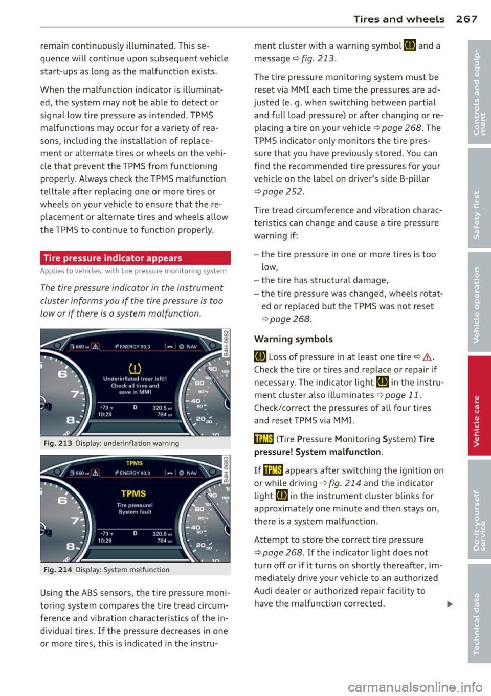
Fig. 213 Display : underi nflatio n warning
Fig. 214 Di splay: Syste m mal functio n
Using the ABS sensors, the tire pressure moni
toring system compares the tire tread circum
ference and vibration ch arac teristics of the in
dividual tires. If the pressure decreases in one
or more tires, this is indicated in the instru-
Tires and wheels 267
ment cluster with a warning symbol [I] and a
message
r::!) fig. 213.
The tire pressure monitoring system must be
reset via MMI each time the pressures are ad
justed (e.g. when switching between partial
and full load pressure) or after changing or re
placing a tire on your vehicle
r::!) pag e 268. The
TPMS indicator only monitors the tire pres
sure that you have previously stored. You can
find the recommended tire pressures for your
vehicle on the label on driver's side 8-pillar
<=:>page 252 .
Tire tread circumference and vibration charac
teristics can change and cause a tire pressure
warning if:
- the tire pressure in one or more tires is too
low,
- the tire has structural damage,
- the tire pressure was changed, wheels rotat-
ed or replaced but the TPMS was not reset
r::!) page 268 .
Warning symbols
[I] Loss of pressure in at least one tire q &..
Check the tire or tires and replace or repair if
necessary. The indicator light
[I] in the instru
ment cluster also illuminates
¢page 11.
Check/correct the pressures of all four tires
and reset TPMS via MMI.
i:mJ) (Tire Pressure Monitoring System) Tire
pressure! System malfunction .
If@m appears after switching the ignition on
or while driving
q fig. 214 and the indicator
light
[I] in the instrument cluster blinks for
approximately one minute and then stays on,
there is a system malfunction .
Attempt to store the correct tire pressure
¢ page 268. If the indicator light does not
turn off or if it turns on shortly thereafter, im
mediately drive your vehicle to an authorized
Audi dealer or authorized repair facility to
have the malfunction corrected .
Page 275 of 314

-Always store the vehicle tool ki t, the jack
and t he replaced t ire in the luggage com
partment ¢
page 141 .
@ Tips
Before chang ing the wheel, you must acti
vate the jacking mode, so that the auto
mat ic controls for the Adaptive Air Sus
pens ion do not make it more difficu lt to
lift the vehicle with the jack¢
page 2 75.
Changing a wheel
When you change a wheel, follow these
quence described below step-by-step and in
exactly that order .
1. Activate the vehicle jack mode
c:;.page275.
2. Remove the decorative whe el co ver* . For
mo re deta ils see also
c:;, page 2 73, Deco
rative wheel covers
or c:;, page 2 7 4,
Wheels with wheel bolt caps.
3 . Loosen the wheel bo lts c:;, page 2 7 4.
4. Locate the proper mo unt ing po int for the
jack and align the jack below that point
c:;, page 2 75.
5 . Rai se the car w ith the jack c:;, page 275.
6. Remove the wheel with the flat tire and
then install
the spare c:;, page 2 76 .
7. Tighten all wheel bo lts light ly .
8 .
Lower the ve hicle w it h the jack.
9 . Use t he wheel bolt wre nch and
firmly
tighte n all whee l bolts c:;. page 274.
10. Rep lace the de corative wheel cover* .
11. D eactivate the vehicle jack mode in t he
MMI:
! CARI fu nction button > Car system s
control button > Servicing & che cks > Air
susp.: jack mode > Off .
The vehicle jack mode sw itches off automati
cally at speeds above 10 km/h.
A WARNING
Always read and follow all WARNINGS and
information
c:;, .&. in Raising the vehicle on
page 275
and c:;, page 277.
What do I d o now ? 273
After changing a wheel
A wheel change is not complete without the
doing the following.
.,. Always store the vehicle tool kit, the jack*
and the replaced tire in the luggage com
partment
c:;, page 141 .
.,. Check the tire pressure on the spare whee l
immed iate ly afte r mounting i t.
.,. As soon as poss ib le, have the
tight ening
torque s
on all wheel bolts checked w ith a
torque wrenc h. The co rrec t tighten ing tor
que is 90 ft lb (120 Nm).
.,. Have the flat tire
replaced as soon as possi
ble .
@ Tips
-If you notice that the wheel bo lts a re
corroded and difficult to turn while
chang ing a tire, they should be replaced
before you c heck the tightening torque.
- Drive at reduced speed until you have the tightening torques checked .
- After changing a whee l, the ti re press ure
in all four tires must be checked/correct
ed and the tire press ure monitoring ind i
cator must be sto red in the M MI
c:;. page268 .
Decorative wheel covers
Applies to veh icles: w ith decorative w hee l cove rs
The decorative wheel covers mus t be removed
first to access the wheel bolts.
Fi g. 22 1 Chang ing a whee l: Re moving th e w hee l cover
Removing
.,. Insert the hook (provided with the vehicle
t oo l kit) in the ho le in the whee l hub cover .
i,,.
Page 278 of 314
276 What do I do n ow ?
(D Note
Do not lift the vehicle by the si ll. Position
the vehicle jack only at the designated lift
ing points on the sill. Otherwise, your vehi
cle will be damaged.
{l) Tips
The vehicle jack mode switches off auto
mat ica lly at speeds above 10 km/h .
Taking the wheel off/installing the spare
Follow these instructions step-by-step for
changing the wheel.
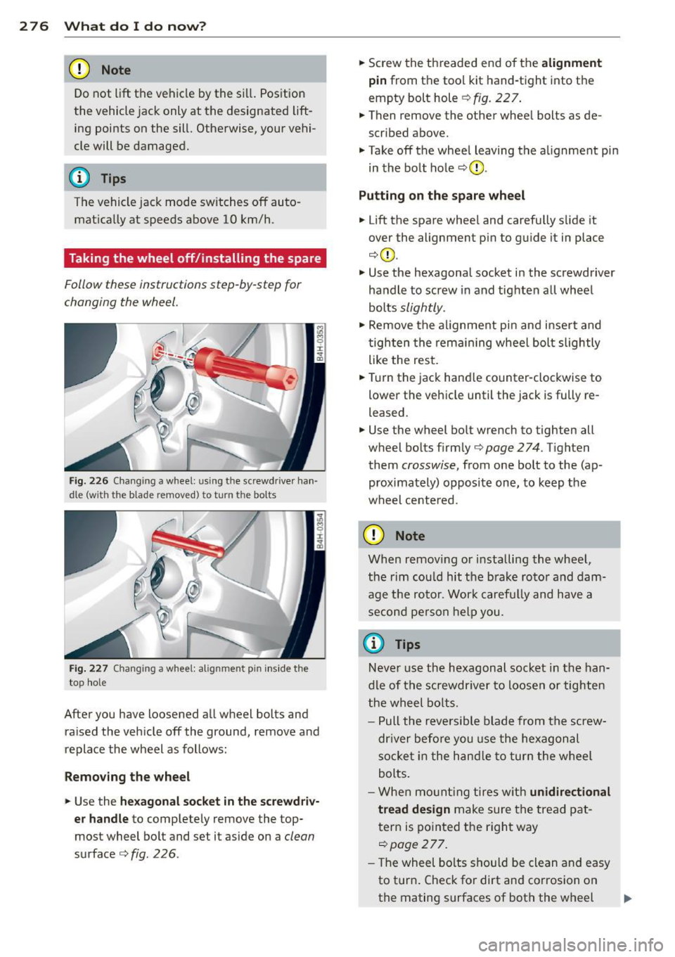
Fi g. 2 26 Cha ngin g a w hee l: u sing t he sc rewdrive r ha n·
dl e (w it h th e blade r emov ed) t o tu rn th e bolt s
F ig. 22 7 Chang ing a w hee l: a lig nm en t pi n inside t he
t op hole
After you have loosened a ll wheel bolts and
ra ised the ve hicle off the ground,
remove and
replace the wheel as follows:
Removing the wheel
.. Use the hexagonal socket in the screwdri v
er handle
to comp letely remove the top·
most wheel bo lt and set it as ide on a
clean
surface ¢fig . 226 .
.. Sc rew the th readed end of the alignment
pin
from t he tool kit hand-tight into t he
empty bolt hole¢
fig. 22 7 .
.. Then remove the other whee l bolts as de
scribed above.
.. Take off the whee l leaving the a lignment pin
in the bo lt hole
c::> (D .
Putting on the spare wheel
.. Lift the spare whee l and carefu lly s lide it
over the alignment p in to g uide it in place
¢ (D .
.. Use the hexagonal socket i n the screwdriver
ha ndle to screw in and tighten a ll whee l
bolts
slightly .
.. Remove the alignment pin and inse rt and
tighten the rem aining wheel bol t slightly
like the res t .
.. Turn the jack hand le co unter-cloc kwise to
lower the vehicle until the jack is fully re
leased .
.. Use the wheel bo lt wrench to tighten all
wheel bo lts firm ly
c;, page 2 74 . Tighten
them
crosswise, from one bolt to the (ap
proximately) opposite one, to keep the
wheel ce nte red.
(D Note
When remov ing or installing th e whe el,
th e rim cou ld hit the b rake ro to r and dam
age the ro tor. W ork caref ully and have a
s eco nd pers on h elp yo u.
{i) Tips
N eve r use the he xagona l socket in the han
d le of t he s crewdr iver to lo ose n or t igh ten
t he wheel bo lts .
- P ull the revers ible blade from the screw
dr iver be fore y ou use the hexagon al
s o ck et in t he han dle to tur n t he w heel
bolts.
- W he n m oun tin g ti res w ith
unidirectional
tread design
make sure t he tre ad pat
t er n is poin ted t he righ t way
c;, page277.
- Th e wheel bolts shou ld be clean and easy
to t urn. Check for dirt an d corrosion on
the mating surfaces of both the w heel
Page 281 of 314
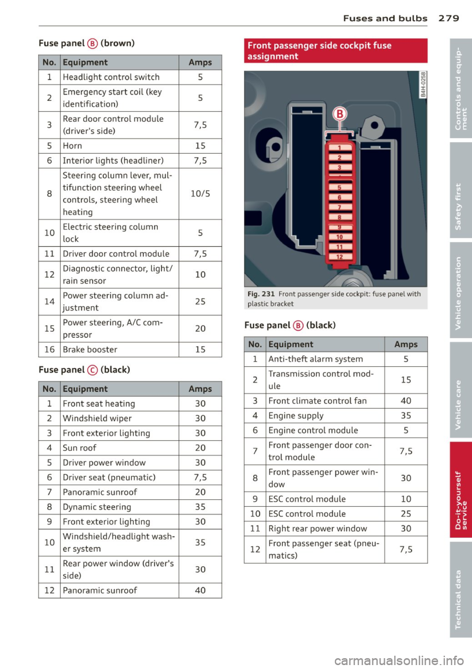
Fuse pa nel @ (brown )
No . Equipment
1 Headlight contro
l switch
2 Emergency
start coil (key
i dentification)
3 Rear door
control module
(driver's side)
5 Horn
6 Interior
lights (headliner)
Steer ing column leve r, mul-
8
tifunction steering wheel
controls, steering wheel
heating
10 E
lectric steering column
l ock
11 Driver door
control module
12 D
iagnostic connector, light/
rain sensor
14 Powe
r steering column ad-
justment
15 Power steering, A/C com-
presser
16 Brake booster
Fu se p anel © (black )
No. Equipment
1 Front seat heating
2 Windshield
wiper
3 Front exte rior lighting
4 Sun roof
5 D river power window
6 Driver
seat (pneumatic)
7 Pano ramic sunroof
8 Dynamic
steering
9 Front exterior lighting
10 W
indshield/headlight wash-
er system
11 Rear power
window (driver's
side)
12 Panoramic sunroof
Amp s
5
5
7,5 15
7,5
10/5
5
7,5
10
25
20 15
Amp s
30
30 30
20
30
7,5 20
35
30
35
30
40
Fu ses and bulb s 2 79
Front passenger side cockpit fuse
assignment
Fig . 231 Front passenger side cockpit: f use pane l with
plast ic bracket
Fu se panel @ (bl ac k)
No. Equipment Amps
1 Anti-theft alarm system 5
2 Transmission control
mod-
15
ule
3 Front climate control fan
40
4 Engine supply 35
6 Engine cont ro l modu le 5
7 Front
passenger door con-
7,5
trol module
8
Front passenger power win-
30
dow
9 E5C contro l module 10
10 ESC
contro l modu le
25
1 1 Right rear power window 30
1 2 Front
passenger seat (pneu-
7,5
matics)
•
•
Page 282 of 314

280 Fuses and bulbs
Luggage compartment fuse assignment
Fig. 23 2 Luggage compartment: fuse pa nel with plas tic bracket
Fuse panel @ (black )
No. Equipment Amps
No. Equipment Amps
11 Dynam ic steer ing 5
E SC button, da ta logger, di· 12
Selector lever,
BCM-2
5
1 agnostic connector, BCM · 1,
5 13 Audi s ide ass ist 5
adap tive light ing system
14 Engine control modu le
5
2 Networking gateway
5
15 Sta rter 40
3 adap tive air s usp ension 5
4 Parking system
5 16 Left headlight/Headlight
10/5
range control system
5 Steering colum n leve r 5
6
Suspension contro l system
5
sensor
Fu se panel @ (red)
No. Equipment Amps
7 Bel
t tensione rs, airbag con-
5
trol module
Heated washe r fl uid no zzles, 1
Left reversible be
lt tens ioner
2S
2 Right revers
ible belt ten -
25
sioner
H ome link (garage door
Starter diagnos is, DC/DC
8 opener), nig ht vision system 5
3 co
nverter (S tart-Stop-Sys·
5
con trol mod ule, sport diffe r-
tern)
ent ia l, ionizer
9
Electromechan ica l park ing
5
brake contro l modu le 4
DC/DC converter (Start-
7,5
Stop-System)
5 Image proce ssing 7,5
10 Rear seat heating, coo
ler, in·
5
terior rearview mirror
Page 283 of 314
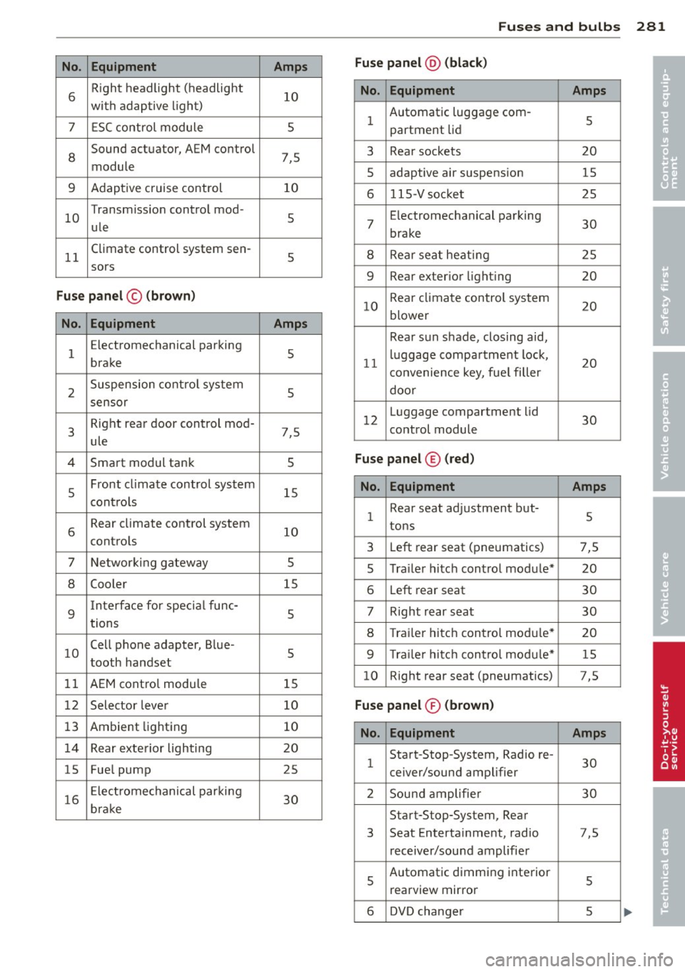
Fuses and bulb s 281
No . Equ ipment Amps Fus
e pan el@ (bla ck)
•
6 R
ight headlight (headlight
10
with adaptive light)
7 ESC control module 5 No. Equipment Amps
1 Automatic luggage com
-
5
partment lid
•
8
Sound actuator, AEM control
7,5
module 3 Rear
sockets 20
5 adaptive air suspension
15
9 Adaptive cruise control 10
6 115-Vsocket 25
10 Transmiss
ion control mod-
5
ule 7 E
lectromechanical parking
30
brake
11 Climate control
system sen-
5
8 Rear seat heating 25
sors
9 Rear exterior lighting 20
Fuse pan el© (bro w n)
No. Equipment Amps
10 Rear climate control system
20
blower
1 E
lectromechanical parking
5
brake
2 Suspension control system
5 Rear
sun shade, closing aid,
11 luggage
compartment lock,
20
convenience key, fue l filler
door
sensor
3 Right rear door
control mod-
7,5
ule 12
Luggage compartment
lid
30
control module
4 Smart modul tank 5
Fuse panel ® (red)
5 Front
climate control system
15
contro ls
6 Rear climate control
system
10
controls N o. Eq uipm ent Amps
1 Rear
seat adjustment but-
5
tons
3 Left rear seat (pneumatics) 7,5
7 Networking gateway 5
5 Tra
iler hitch control module* 20
8 Cooler
15
6 Left rear seat 30
9
Interface for specia l func-
5
tions 7 Right rear seat
30
8 Trailer hitch contro l module*
20
10 Cell phone
adapter, Blue-
5
tooth handset
9 T ra iler hitch control modu le* 15
11 AEM control modu le 15 10
Right rear
seat (pneumatics) 7,5
12 Selector lever 10
Fuse pan el® (bro wn)
13 Ambient lighting
10 No. Equipment Amps
14 Rear exterior lighting 20
15 Fuel
pump
25 1 Start-Stop-System,
Radio re-
30
ceiver/sound amplifier
16 Electromechanical parking
30
brake 2 Sound amplifie
r 30
Start-Stop-System, Rear
3 Seat
Entertainment, radio 7,5
receiver/sound amplifier
5 Automatic dimming interior
5
rearview mirror
6 DVD changer 5