AUDI A8 2015 Owners Manual
Manufacturer: AUDI, Model Year: 2015, Model line: A8, Model: AUDI A8 2015Pages: 312, PDF Size: 79.18 MB
Page 271 of 312

.... N .... N
0 J:
-
"' ....
Spare wheel
Applies to vehicles: with spare wheel
The spare wheel is stored in the wheel well
underneath the floor panel in the luggage
compartment.
F ig. 220 Luggag e co mpartm ent : spar e wh eel
Taking out the sp are whee l
• Lift the cargo floor by the plast ic handle
c:::>fig . 220.
• Hook the hand le into the luggage compart
ment weather strip .
• Turn the large screw
c:::> fig. 220 counter
clockwise.
• Takeout the spare tire.
• Always store the vehicle tool kit , the jack*
and the replaced tire in the luggage com
partment
c:::> page 139 .
• Unhook the ca rgo floor before closing the
rear lid.
& WARNING
-
Loose items in the passenger compart
ment can cause serious pe rsonal in jury
during hard braking or in an accident.
- Never store the spare wheel or jack and
tools in the passenger compartment.
@ Tips
Check the inflat ion p ressu re of the spare
tire periodically to keep the tire ready for
use.
What do I d o now ? 269
Changing a wheel
Before changing a wheel
Observe the following precautions for your
own and your passenger's safety when chang
ing a wheel.
• After you experience a t ire failure, pull the
car well away from moving traffic and try to
reach
leve l ground before you stop c:::> ,&.
• All passengers should le av e t he ca r and
move to a safe location (for ins tance, behind
t he guardra il)
c:::> ,& .
• Engage the parki ng br ake to prevent your
vehicle from rolling unintentionally
c:::> ,& .
• Move sele ctor lever to po sit ion P c:::> ,&. .
• If you are towing a trailer, unhitch the trailer
from your ve hicle.
• Take the
jac k and the sp are tire out of the
luggage compartment
c:::> page 267,
c:::> page 268 .
& WARNING
You o r you r passengers could be i njured
while changing a wheel if you do not fo l
low these safety precaut ions:
-I f you have a flat tire, move a safe d is
tance off the road. Turn off the engine,
turn the eme rgency flashers on and use
other warning devices to a lert other mo
torists .
- Make sure that passengers wait in a safe
place away from the vehicle and well
away from the road and traffic.
- To help prevent the vehicle from moving
suddenly and possibly slipping off the
jack, always f ully set the parking brake
and b lock the wheel d iagonally opposite
the wheel be ing changed. When one
front wheel is lifted off the ground, plac ing the Automatic Transmission in "P"
(Par k) will
not prevent the vehicle from
mov ing .
- Before you change a wheel, be sure the
ground is level and firm. If necessary,
use a sturdy board under the jac k.
-
Page 272 of 312
2 70 What do I do now ?
-Always store the vehicle tool kit, the jack
and the replaced t ire in the luggage com
partment ¢
page 139.
@ Tips
Before changing the wheel, yo u m ust acti
vate t he jac king mode, so t hat the auto
mat ic cont rols fo r the Adaptive Air S us
pens io n do not make it mo re diff ic u lt to
lift the vehicle with the jack
c.';> page 2 72.
Changing a wheel
When you change a wheel, follow these
quence described below step-by-step and in
exactly that order .
1. Activate the vehicle jack mode
¢page 272.
2. Remove the decorative wheel cover* . For
more deta ils see also
¢ page 270, Deco
rative wh eel covers
o r ¢ page 2 71 ,
Wheels with wheel bolt caps.
3 . Loosen the wheel bolts ¢ page 2 71.
4. Locate the proper mo unt ing po in t for the
j ack and align t he jack be low tha t poi nt
¢ page 272 or r::!>page 273.
5. Raise the car with the jack¢ page 272 or
¢page 273.
6. Remove the wheel with the flat tire and
then i nstall
the spare ¢page 274.
7. Tighten all wheel bolts ligh tly.
8 .
Lower th e ve hicle w it h the jack .
9 . Use the whee l bolt wren ch and
firmly
tig hte n al l whee l bolts ¢p age 271.
10. Rep lace the decorative wheel cover* .
11. D eactivate t he ve hicle jack mode in the
M MI :
!CARI function button > Car systems
control button > Se rvicing & checks > Air
susp.: jack mode
> Off .
The vehicle jac k mode sw itches off automati
cally at speeds above 10 km/h.
A WARNING
Always read and follow all WARNINGS and
informati on
¢ .&. in AB: Raising the vehicle
on page 272
and ¢page 275 .
After changing a wheel
A wheel change is not complete without the
doing the following .
.,. Always store the vehicle tool kit, the jack"
and the rep laced tire in the luggage com
pa rtment
¢ page 139.
.,. Check the tire pressure on the spare whee l
immed iate ly afte r mounting i t.
.,. As soon as poss ible, h ave the
tightening
torques
on all whee l bolts che cked with a
torque wre nch. The correc t tig hten ing tor
que is 90 ft l b (120 Nm).
.,. Have the flat tire
replaced as s oon as possi
ble.
@ Tips
- If you not ice that the w heel bo lts a re
co rroded and difficult to turn while
chang ing a tire, t hey shou ld be rep laced
before you check the tig htening to rque.
- Dr ive at reduced speed until you have the
t ightening torques checked.
- After changing a whee l, the t ire p ress ure
in all four tires must be chec ked/co rrect
ed and the tire p ress ure monito ring in di
cator must b e sto red in th e MMI
¢ page 265.
' Decorative wheel covers
Applies to vehicles: w ith decorative whee l covers
The decorative wheel covers must be removed
first to access the wheel bolts.
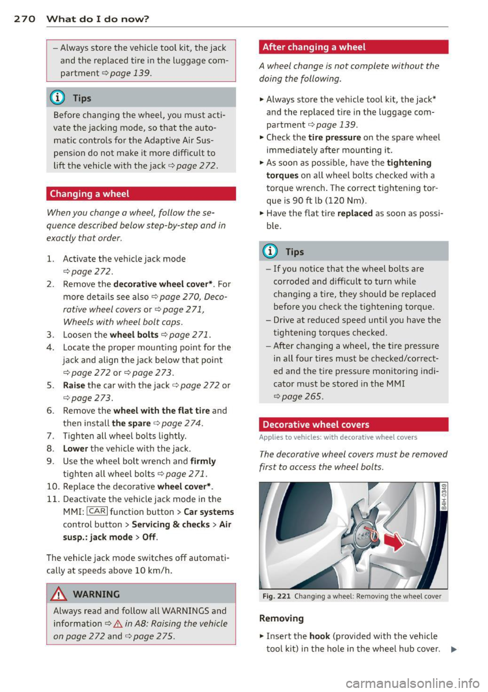
Fig. 2 21 Cha ngin g a w hee l: Remov ing th e w heel cove r
Removing
.,. Insert the hook (prov ided w ith th e vehicle
t oo l ki t) in the hole in the whee l hub cover . ..,.
Page 273 of 312
.... N .... N
0 J:
"". .... I.O
"' ....
"' ....
.. Pull off the decorati ve wheel c over
r=>fig. 221 .
Wheels with wheel bolt caps
Applies to vehicles: with wheel bolts with caps
The caps must be removed first from the
wheel bolts before the bolts can be un
screwed .
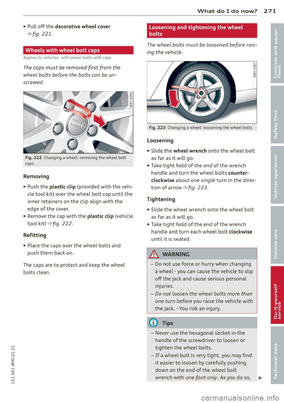
Fig. 222 C hanging a wheel: remov ing the wheel bolt
caps
R em oving
.. Push the pla stic clip (provided with the vehi
cle tool kit) over the whee l bolt cap unt il the
inner retainers on the clip al ign with the
edge of the cover.
.. Remove the cap with the
plas tic clip (vehicle
tool kit)
r=>fig . 222.
R efitting
.. Place the caps ove r the wheel bo lts and
push them back on.
The caps are to protect and keep the wheel
bol ts clean.
What do I d o now ? 271
Loosening and tightening the wheel
, bolts
The wheel bolts must be loosened before rais
ing the vehicle .
Fig . 2 23 Changing a whee l: loosen ing the wheel bolts
Loosen ing
.. Slide the w he el wrench onto the wheel bo lt
as far as it will go .
.. Take tight hold of the
end of the wrench
handle and turn the wheel bo lts
c ounter
cloc kwi se
about one single turn in the direc
tion of arrow
r=> fig . 223.
T ight ening
.. Slide the wheel wrench onto the wheel bolt
as far as it will go.
.. Take tight hold of the
end of the wrench
handle and turn each wheel bolt
clockwise
until it is seated .
A WARNING
-Do not use fo rce or hurry when changing
a wheel - you can ca use the vehicle to slip
off the jack and cause ser ious pe rsonal
inj uries.
- Do not loosen the wheel bo lts more than
one turn
befo re you raise the vehicle with
the jack . -Yo u risk an injury .
(D Tips
-Never use the hexagona l soc ket in the
hand le of the screwdr iver to loosen or
t igh ten the wheel bolts .
- If a wheel bolt is very tight, you may find
it eas ier to loose n by carefully pushing
down on the end of the wheel bolt
wrench with
one foot only. As you do so, Ill>-
Page 274 of 312

272 What do I do now?
hold on to the car to keep your balance
and take care not to slip.
AB: Raising the vehicle
The vehicle must be lifted with the jack first
before the wheel can be removed.
Fig. 224 Sill pa nels : m ark ings
Fig. 225 Sill: position ing t he veh icle jack
.. Activate the vehicle jack mode in the MMI:
I CAR ! function button > Car systems control
button>
Servicing & checks> Air susp.:
jack mode
> On.
.. Engage the parking brake to prevent your
vehicle from rolling unintentionally.
.. Move the
selector lever to position P .
.. Find the marking (imprint) on the sill that is
nearest the wheel that will be changed
o
fig. 224. Behind the marking, there is a
lifting point on the sill for the vehicle jack.
.. Turn the
vehicle jack located under the lift
ing point on the sill to raise the jack until its
arm @o
fig. 225 is located under the des
ignated plastic mount o ,& o0 .
.. Align the jack so that its arm @ o
fig. 225
engages in the designated lifting point in
the door sill and the movable base @ lies
flat on the ground. The base @ must be
ver
tical
under the lifting point @. ..
Wind the jack up further until the flat tire
comes off the ground o
.&,.
Position the vehicle jack only under the desig
nated lifting points on the sill
c:> fig. 224.
There is exactly one location for each wheel.
The jack must not be positioned at any other
location
c:> .&, c:>Q).
An unstable surface under the jack can cause
the vehicle to slip off the jack. Always provide
a firm base for the jack on the ground. If nec
essary place a sturdy board or similar support
under the jack. On
hard, slippery surfaces
(such as tiles) use a rubber mat or similar to
prevent the jack from slipping
c:> .&,.
A WARNING ~
-You or your passengers could be injured
while changing a wheel if you do not fol
low these safety precautions:
- Position the vehicle jack only at the
designated lifting points and align the
jack. Otherwise, the vehicle jack could slip and cause an injury if it does not
have sufficient hold on the vehicle.
- A soft or unstable surface under the
jack may cause the vehicle to slip off
the jack . Always provide a firm base for
the jack on the ground. If necessary,
use a sturdy board under the jack.
- On hard, slippery surface (such as tiles)
use a rubber mat or similar to prevent
the jack from slipping.
- To help prevent injury to yourself and
your passengers:
- Do not raise the vehicle until you are
sure the jack is securely engaged.
- Passengers must not remain in the ve
hicle when it is jacked up.
- Make sure that passengers wait in a
safe place away from the vehicle and
well away from the road and traffic .
- Make sure jack position is correct, ad
just as necessary and then continue to
raise the jack.
- Changes in temperature or load can af
fect the height of the vehicle.
Page 275 of 312

.... N .... N
0 J:
'
"' ....
(D Note
Do not lift the vehicle by the sill. Position
the vehicle jack only at the designated lift
ing points on the sill. Otherwise, your vehi
cle will be damaged.
(D T ips
The vehicle jack mode switches off auto
matically at speeds above 10 km/h.
58: Raising the vehicle
The vehicle must be li~ed with the jack first
before the wheel can be removed.
Fig . 226 S ill pane ls: mark ings
F ig. 227 S ill: posit ion ing the veh icle jack
.. Activate the vehicle jack mode in the MMI:
I CAR I funct ion button > Car syste m s control
button
> Se rvi cing & check s> Air sus p.:
ja ck m ode
> On.
.,. Engage the par kin g brake to prevent your
vehicle from rolling un intentionally.
.. Move the
sel ec tor le ver to po sition P .
.. Find the ma rki ng (imprint) on the sill that is
nearest the wheel that w ill be changed
r=> fig . 226. Behind the marking, there is a
lifti ng po int on the si ll for the vehicle jack.
.. Turn the
ve hicle jack located under the lift
i ng point on the sill to raise the jack until its
What do I d o now ? 273
arm @r=> fig . 22 7 is located under the des
ignated plastic mount
r=> A. in AB: Raising
the vehicle on page 272i::>(f).
.. Align the jack so that its arm @c::> fig. 22 7
engages in the designated lifting point in
the door sill and the movable base @ lies
flat o n the ground. The base @ must be
ver
tical
under the lifting point @.
.. Wi nd the jack up fu rther until the flat t ire
comes off the ground
r=> &,. in AB: Raising
the vehicle on page 272.
Position the vehicle jack only under the desig
na ted lifting points on the s ill
c::>page 272,
fig. 224 .
There is exact ly one l ocation fo r each
whee l. The jack must not be positioned at any
other location c::>
.&. in AB: Raising the vehicle
on page 2 72r=>
(J).
An un sta ble surf ace unde r the jack can cause
the ve hicle to slip
off the jack . Always provide
a firm base for the jack on the gro und. If nec
essary place a sturdy board or simi lar support
under the jack. On
h ard , sl ipp ery surf aces
(such as tiles) use a rubber mat or similar to
prevent the jack from slipping c::>
,&. .
.&_ WARNING
-You or your passengers cou ld be injured
while changing a wheel if you do not fo l
low these safety p re cautions:
- Position the vehicle jack on ly at the
designated lifting points and align the
j ack. Otherw ise, the vehicle jack could
slip and cause an injury if it does not
have sufficient hold on the vehicle.
- A soft or unstable surface under the
j ack may cause the veh icle to slip off
the jack . Always provide a firm base for
the jack on the ground .
If necessary,
u se a st urdy board under the jack .
- On hard, slippery surface (such as t iles)
use a rubber mat or similar to prevent
the jack from slipping .
- To help pr event injury to yourself and
your passengers:
- Do not raise the vehicle until you are
sure the jack is securely engaged .
Page 276 of 312
274 What do I do now ?
-Passengers must not rema in in the ve
h icle when it is jacked up.
- Make sure that passengers wait in a
safe p lace away from the vehicle and
well away from the road and traffic.
- Make sure jack position is correct, ad
just as necessary and then continue to
raise the jack.
- Changes in temperature or load can af
fect the height of the vehicle.
CD Note
D o not lift t he vehicle by the si ll. Position
the vehicle jack only at the designated lift
ing points on the sill. Otherwise, your vehi
cle will be damaged.
@ Tips
The vehicle jack mode switches off auto mat ica lly at speeds above
10 km/h.
Taking the wheel off/installing the spare
Follow these instructions step-by-step for
changing the wheel.
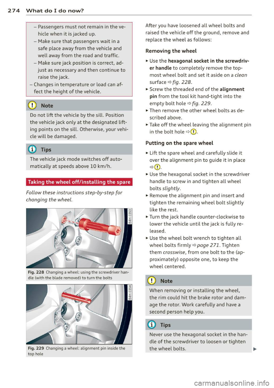
Fi g. 228 Changing a wheel: using the screwdrive r han
dle (w ith t he blade r emoved) to turn the bo lts
F ig . 2 29 Changing a whee l: a lignmen t pin inside th e
top hole
After yo u have loosened all wheel bo lts and
raised the vehicle off the ground, remove and
replace the wheel as follows:
Removing the wheel
.,. Use the hexagonal soc ket in the scr ewdriv
er handle
to completely remove the top
most whee l bolt and se t it aside on a
clean
surface r=> fig. 228 .
.,. Screw the threaded end of the alignme nt
pin from the tool kit hand-t ight into th e
empty bolt hole
Q fig. 229 .
.,. Then remove the other whee l bolts as de
scribed above.
.,. Take off the whee l leaving the a lignment pin
in the bo lt ho le r=> 0 .
Putting on the spare wheel
.,. Lift the spare whee l and carefully s lide it
over the alignment p in to g uide it in place
Q0 .
.,. Use the hexagona l socket in th e screwdriver
ha ndle to screw in and tig hten all whee l
bolts
slightly.
.,. Remove the al ignment pin and insert and
tighten the remain ing wheel bolt slightly
like the rest .
.,. Turn the jack hand le counter-clockwise to
lower the vehicle until the jack is fully re
leased .
.,. Use the wheel bo lt wrench to tighten all
wheel bo lts fi rm ly
r=> page 271 . Tighten
them
crosswise, from o ne bolt to the (ap
p rox ima tely) opposi te one, to keep the
wheel ce nte red .
CD Note
When remov ing or i nsta lling the whee l,
the rim could hit t he b ra ke ro to r and d am
age the ro tor. Wor k caref ully and have a
seco nd person hel p you.
(D Tips
Never use the hexagon al socke t in the han
d le of t he screwdriver to loosen or tighten
the wheel bo lts .
Ill-
Page 277 of 312
,....,
N .... N
0 J:
'SI: .... \!) ..,.,
.... ..,., ....
-Pull the reversible blade from the screw
driver before you use the hexagonal
socket in the handle to turn the wheel
bolts.
- When mounting tires with
unidirectional
tread design
make sure the tread pat
tern is pointed the right way
<=>pag e 275.
- The wheel bolts should be clean and easy
to turn. Check for dirt and corrosion on
the mating surfaces of both the wheel
and the hub . Remove all dirt from these
surfaces before remounting the wheel.
Tires with unidirectional tread design
Tires with unidirectional tread design must be
mounted with their tread pattern pointed in the right direction.
Using a spare tire with a tread pattern
intended for use in a specific direction
When using a spare tire with a tread pattern
intended for use in a specific direction, please
note the following:
- The direction of rotation is marked by an ar
row on the side of the tire.
- If the spare tire has to be installed in the in
correct direction, use the spare tire only
temporarily since the tire will not be able to
achieve its optimum performance character
istics with regard to aquaplaning, noise and
wear.
- We recommend that you pay particular at
tention to this fact during wet weather and
that you adjust your speed to match road
conditions.
- Replace the flat tire with a new one and
have it installed on your vehicle as soon as
possible to restore the handling advantages
of a unidirectional tire.
Notes on wheel changing
Please read the information <=> page 256, New
tires and replacing tires and wheels
if you are
going to use a spare tire which is different
from the tires on your vehicle .
What do I do now? 275
After you change a tire:
-Check the tire pressure on the spare imme
diately after installation.
- Have the wheel bolt tightening torque
checked with a torque wrench as soon as
possible by your authorized Audi dealer or
a qualified service station.
- With steel and alloy wheel rims, the wheel
bolts are correctly tightened at a torque of
90 ft lb (120 Nm).
- If you notice that the wheel bolts are cor
roded and difficult to turn while changing
a tire, they should be replaced before you
check the tightening torque.
- Replace the flat tire with a new one and
have it installed on your vehicle as soon as
possible. Remount the wheel cover.
Until then, drive with extra care and at re
duced speeds.
A WARNING
-
- If you are going to equip your vehicle
with tires or rims which differ from those
which were factory installed, then be sure to read the information<=>
page 256,
New tires and replacing tires and
wheels .
-Always make sure the damaged wheel or
even a flat tire and the jack and tool kit
are properly secured in the luggage com
partment and are not loose in the pas
senger compartment .
- In an accident or sudden maneuver they
could fly forward, injuring anyone in the
vehicle.
-Always store damaged wheel, jack and
tools securely in the luggage compart
ment. Otherwise, in an accident or sud
den maneuver they could fly forward,
causing injury to passengers in the vehi
cle. •
•
Page 278 of 312
2 76 Fuses and bulbs
Fuses and bulbs
Fuses
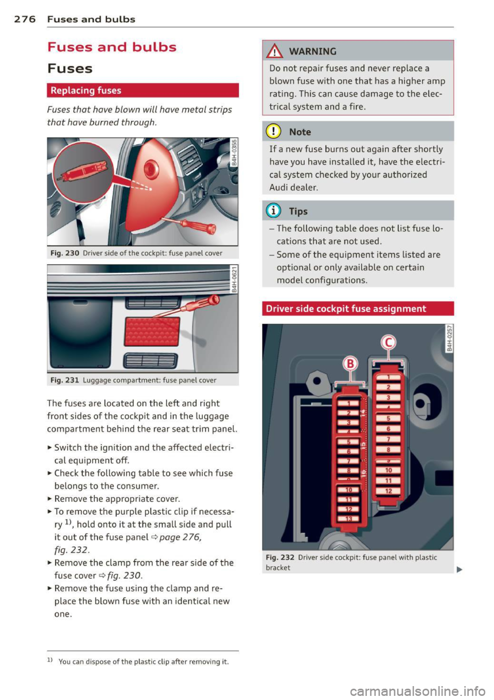
Replacing fuses
Fuses that have blown will have metal strips
that have burned through.
Fig. 230 Dr iver side of the cockpit: fuse panel cover
Fi g. 231 Luggage compartment: fuse panel cover
The fuses are located on the left and r ight
front sides of the cockp it and in the luggage
compartment behind the rear seat tr im panel.
.,. Switch the ign ition and the affected electri-
cal equ ipment off .
.,. Check the following table to see which fuse
belongs to the consume r .
.,. Remove the appropriate cover .
... To remove the purple plastic clip if necessa
ry
1l, ho ld onto it at the sma ll s ide and pull
it out of the fuse panel <=>
page 2 76,
fig. 232.
.,. Remove the clamp from the rear s ide of the
fuse cover <=>
fig. 230 .
.,. Remove the fuse using the clamp and re
pla ce the blown fuse w ith an identical new
one.
l l You can dispose of t he plastic clip after removing it .
A WARNING
-Do not repair fuses and never replace a
b lown fuse with one that has a higher amp
rat ing. Th is can cause damage to the elec
tr ica l system and a fire.
(D Note
If a new fuse burns out again after shortly
have you have insta lled it, have the electri
ca l system checked by you r authorize d
A udi dealer.
(D Tips
- The following table does not list fuse lo
cat ions that are not used.
- Some of the equipment items listed are
optional or only ava ilable on certa in
mode l configurations.
Driver side cockpit fuse assignment
Fig . 232 Dr iver side cockp it: fuse pane l w ith plast ic
b racket
Page 279 of 312

.... N .... N
0 J:
'SI: .... \!) 1.1'1
.... 1.1'1 ,-0
Fuse pa nel @ (brown )
No . Equipment
1 Headlight contro l switch
2
Emergency start coil (key
i dentification)
3
Rear door control module
(driver's side)
4 Head-up Display
5 Horn
6 Inter ior lights (head liner)
Steering column lever, mul-
8
tifunction steering wheel
controls, steering wheel
heat ing
10
Electric steering co lumn
lock
11 D river door contro l modu le
12
D iagnostic connector, light/
rain sensor
14
Power steering col umn ad -
justment
15
Power steering, A/C com-
presse r
16 Brake booster
Fu se pa nel © (b la ck)
No . Equipment
1 Front seat heating
2 Windshield w iper
3 Front exterior lighting
4 Sun roof
5 Driver power window
6 Driver seat (pneumat ic)
7 Panoramic sunroof
8 Dynamic steering
9 Front exterior lighting
10 Windshield/headlight
wash-
er system
11
Rear power w indow (driver's
side)
12 Panoramic sunroof
Amps
5
5
7,5 5
15
7,5
10/5
5
7,5 10
25
20
15
Amps
30 30
30 20
30
7,5
20 35
30
35
30
40
Fu ses and bulb s 2 77
Front passenger side cockpit fuse
assignment
Fig . 233 Fro nt passe nger side cockpit: f use pane l with
plast ic brac ket
Fu se panel @ (bl ac k)
No. Equipment Amps
1 Anti-theft alarm system 5
2
Transmission control mod-
15
ule
3 Front climate control fan 40
4 Engine supply 35
6
Engine cont ro l modu le 5
7
Front passenger door con-
7,5 trol module
8
Front passenger power win-
30 dow
9 ESC contro l module
10
10
ESC contro l modu le 25
1 1
Right rear power window 30
1 2
Front passenger seat (pneu-
7,5 matics)
•
•
Page 280 of 312
2 78 Fuses and bulbs
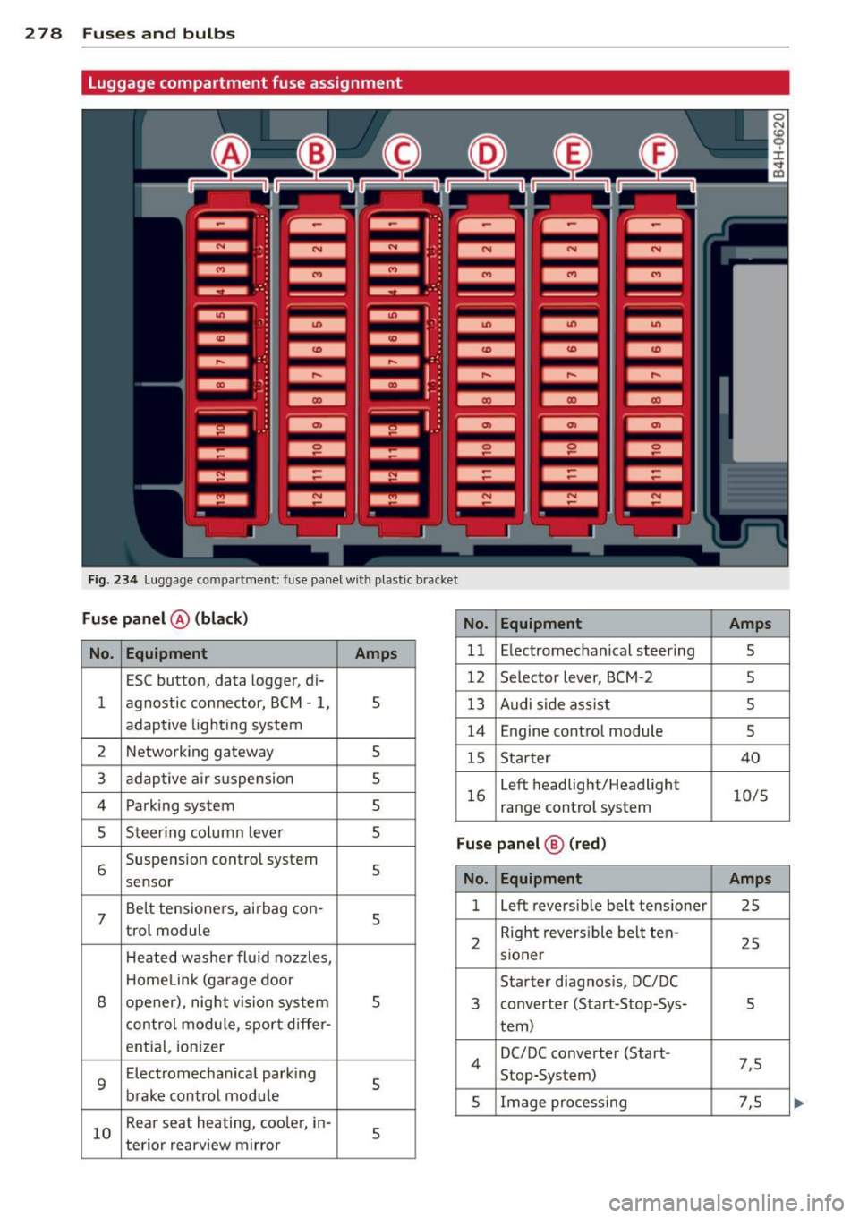
Luggage compartment fuse assignment
Fig. 234 Luggage compartment: fuse pa nel with plastic bracket
Fuse p ane l@ (black) No. Equipment Amps
No . Equ ipm ent Amps
11 E lectromechanical steering 5
ESC button, data logger, di· 12
Selector lever,
BCM-2
5
1 agnostic connector, BCM · 1, 5
13 Audi side ass ist 5
adaptive light ing system
14 Engine control module
5
2 Networking gateway
5
15 Starter 40
3 adaptive air suspension 5
4 Parking system
5 16 Left headlight/Headlight
10/5
range control system
5 Steering column lever
5
6 Suspension control system 5 sensor
Fu
se p an el@ (red )
No. Equipment Amps
7
Belt tensioners, airbag con-
5
trol module
Heated washer fluid nozzles, 1
Left reversible belt
tensioner
2S
2 Right reversible belt
ten-
25
sioner
H ome link (garage door
Starter diagnos is, DC/DC
8 opener), night vision system 5
3 converter (Start-Stop-Sys·
5
control module, sport differ- tern)
ential, ionizer
9
Electromechanical parking 5
brake control module 4
DC/DC converter (Start-
7,5 Stop-System)
5 Image processing
7,5
10 Rear
seat heating, cooler, in· 5 terior rearview mirror