radio AUDI A8 2016 Owners Manual
[x] Cancel search | Manufacturer: AUDI, Model Year: 2016, Model line: A8, Model: AUDI A8 2016Pages: 302, PDF Size: 75.68 MB
Page 18 of 302
Instruments and indicator lights
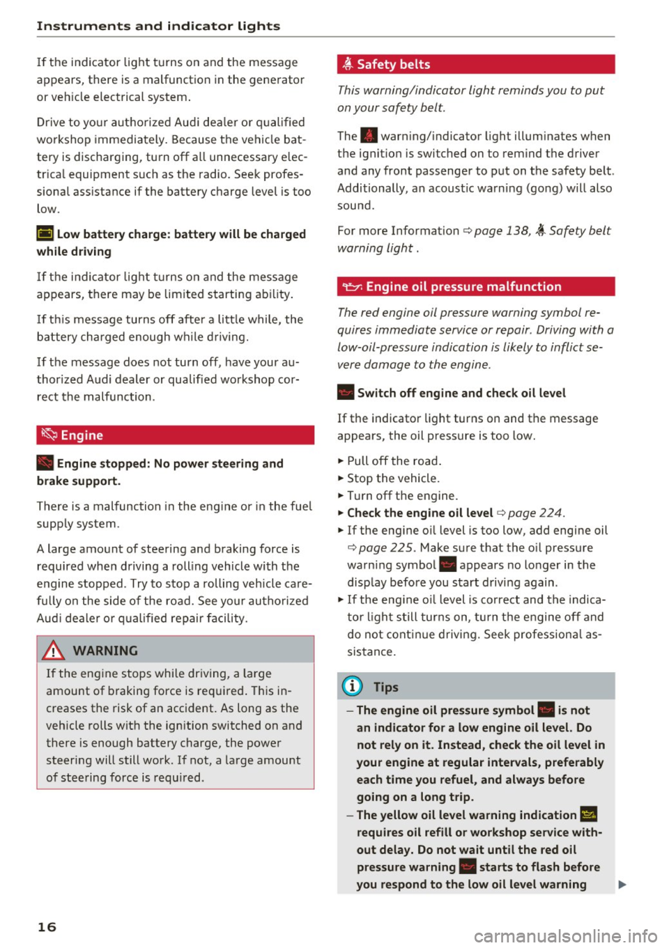
If the indicator light t urns on and the message
app ears, th ere is a malfunction in the gene rator
or veh icle electrical system .
Drive to yo ur autho rized Aud i dea le r o r q ual ified
workshop immediately . Because the vehicle bat
tery is discharging, turn off a ll unnecessary e lec
tr ica l equipment s uch as the radio. Seek profes
sional ass istance if the battery charge level is too
low.
(•) Low b attery charge: b attery w ill be charged
while dri ving
If th e ind icator lig ht tu rns on and the message
appears, there may be lim ited starting ab ility .
I f th is message turns off afte r a litt le while, the
b a ttery charged enough wh ile d riving.
If the message does not turn off, have your a u
thor ized Audi dealer or qualified wo rkshop cor
re ct the malfunction .
~ Engine
• Engin e stopp ed: No power steering and
brake support .
There is a malfunction in the eng ine or in the fue l
supp ly system .
A large amount of steering and braking force is required when driving a rolling vehicle with the
e ng ine stopped . Try to stop a rolling vehicle ca re
fu lly on the side of the road. See your autho riz ed
Aud i deale r or qualified repair facility.
A WARNING
-
If the eng ine stops while dr iving, a la rge
amount of braking force is req uired . This in
creases the risk of an accident. As long as the
vehicle rolls with the ignition switched on and there is enough battery charge, the powe r
steering will still work . If not, a la rge amount
o f stee ring force is requ ired .
16
~ Safety belts
This warning/indicator light reminds you to put
on your safety belt.
The . warn ing/ indicator light illumin ates when
the igni tion is swi tched on to remind th e driver
and any front passenger to put on the safety belt .
Additionally, a n acoust ic wa rning (go ng) w ill also
sou nd.
For more Information
c::> page 138, ~ Safe ty belt
warning light .
"1::::1': Engine oil pressure malfunction
The red engine oil pressure warning symbol re
quires immediate service or repair . Driving with a
low-oil-pressure indication is likely to inflict se
vere damage to the engine.
• Switch o ff engine and check oil le vel
If the indicator light turns on and the message
appears, the oil pressure is too low .
.. Pull off the road .
.. Stop the vehicle.
.. Turn off the engine .
.. Che ck the engine oil le vel c::> page 224.
.. If the eng ine o il level is too low, add engine oil
c::> page 22 5 . Make sure tha t t he o il pressure
warning symbol. appears no longer in the
display before you sta rt d riving again .
.. If the eng ine o il level is co rrect and the indica
to r li ght still turns on, tu rn t he e ngine off and
do not cont inue d riv ing. Seek professiona l as
sistance.
(D Tips
- The engine oil pres sure symbol. is not
an indicator for a low engine oil level. Do
not rel y on it . In stead , check the oil level in
your engine at regular inte rvals , preferably
each time you refuel , and always before
go ing on a long trip .
- The yellow oil level warning indication
II
require s oil refill o r workshop servi ce with
out delay. Do not wait until the red o il
pre ssure wa rning. starts to flash before
you respond to the low oil le vel warning .,.
Page 32 of 302
Opening and closing
Opening and closing
Keys
Key set
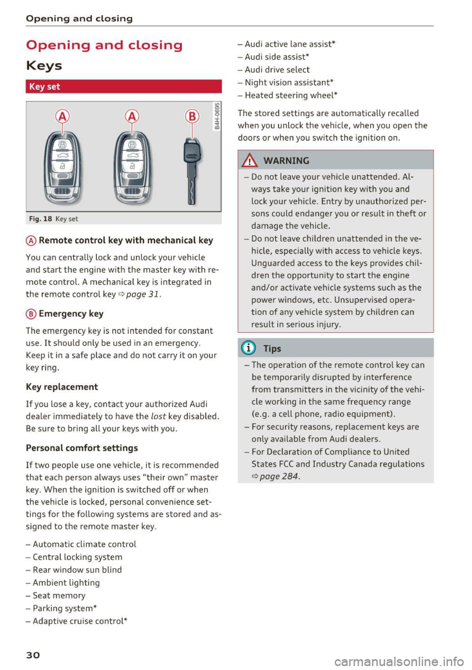
Fig. 18 Key set
@ Remote control key with mechanical key
You can centrally lock and unlock your vehicle
and start the engine w ith the master key with re
mote control. A mechanical key is integrated in
the remote control key¢
page 31.
@ Emergency key
The emergency key is not intended for constant
use. It shou ld only be used in an emergency.
Keep it in a safe place and do not carry it on your
key ring.
Key replacement
If you lose a key , contact your authorized Audi
dealer immediately to have the
lost key disab led .
Be sure to bring all your keys with you.
Personal comfort settings
If two people use one vehicle, it is recommended
that each person always uses "their own" master
key. When the ignition is switched off or when
the vehicle is locked , personal convenience set
tings for the following systems are stored and as
signed to the remote master key .
- Automatic climate contro l
- Central locking system
- Rear w indow sun blind
- Amb ient lighting
- Seat memory
- Parking system*
-Adaptive cruise contro l*
30
- Audi active lane assist*
- Audi side assist*
- Audi drive select
- Night vision assistant*
- Heated steering wheel*
The stored settings are automatica lly recalled
when you unlock the vehicle, when you open the
doors or when you switch the ignition on.
A WARNING
-
- Do not leave your vehicle unattended . Al
ways take your ignition key with you and
lock your vehicle. Entry by unauthorized per
sons could endanger you or result in theft or
damage the vehicle.
- Do not leave children unattended in the ve
hicle, especially with access to vehicle keys.
Ungua rded access to the keys provides chil
dren the opportunity to start the engine
and/or activate vehicle systems s uch as the
power windows, etc . Unsupervised opera
tion of any veh icle system by ch ildren can
result in serious injury.
(D Tips
- The operation of the remote control key can
be temporarily disrupted by interference
from transmitters in the v icinity of the vehi
cle working in the same frequency range
(e.g . a cell phone, radio equipment).
- For security reasons, replacement keys are
only available from Audi dealers.
- For Declaration of Compliance to United
States FCC and Industry Canada regulat ions
C?page 284.
Page 34 of 302
Opening and closin g
(D Tips
- The vehicle cannot be started if an unau
thorized key is used. The veh icle may not
start if another radio device such as a key
for another vehicle or a transponder is lo
cated on the key ring.
- For Declaration of Comp liance to Un ited
States FCC and Industry Canada regulations
<=> page 284.
Central locking
General description
The power locking system locks or unlocks all
doors and the luggage compartment lid simulta
neously .
You can lock and un lock the veh icle cent rally. You
have the following cho ices:
- Remote master key <=>
page 33,
-Door handles with convenience key*
¢ page 34,
-Lock cylinder at the driver's door<=> page 35,
or
- Power lock ing switch ins ide <=>
page 35.
Sel ective unloc king
When you lock the vehicle, the powe r locking sys
tem wi ll lock the doors and the luggage compart
ment lid . When un locking, you can set in the
MMI whether only the driver's door or the entire
ve hicle should be unlocked
<=>page 33.
Automatic locking
The automatic locking feature locks a ll the vehi
cle doors and the luggage compartment lid when
you drive faster than 9 mph (15 km/h).
The car is un locked again, when the open ing
function in the power locking system switch or at
one of the door levers is actuated . The Auto Lock
function can be turned on and off in the MMI
<=> page 33.
Ant i-theft alarm warning syst em
If t he anti-theft alarm warning system detects a
b reak -in into the vehicle, acoustic and visua l
warning signals are triggered.
32
The anti-the ft warn ing system is activated a uto
matically when you lock the vehicle. It is deacti
vated when unlock ing us ing the remote key, w ith
the mechanical key, and when you sw itch the ig
nit ion on.
The alarm also turns off when the alarm cycle has expired.
Turn signals
When yo u un lock the veh icle, the turn s ignals
flash twice . When you lock the vehicle once, the
turn signals flash once. If they do not flash, one
of the doors, the luggage compartment lid or the hood is not locked.
Unintentionally locking yours elf out
In the follow ing cases there safeguards to p re
vent you locking your remote master key in the
vehicle:
- T he vehicle does not lock w ith the cent ral lock
ing switch¢
page 35 if t he d river's doo r is
open.
- On veh icles with co nvenience key*, if the most
recent ly used master key is in the l uggage com
partment, the luggage compartment lid is a u
tomatically un locked again after it is closed .
Do no t lock your ve hicle w ith the
re mote ma ste r
key or conv enienc e ke y*
unti l all doors and the
lu ggage compartment lid are closed. In this way
you avoid locking yourse lf out accidenta lly.
Power s ide door closer *
The vehicle doo rs a re equipped with a power side
door closer. Whe n clos ing a door, you on ly have
to let i t fall lightly into the latch. The door w ill
then a utomatica lly close by itself¢& .
A WARNING
-
-When you lock yo ur vehicle from outside,
nobody -espec ially children -sho uld rema in
inside the vehicle. Remember, when you
lock the vehicle from the outside the win
dows cannot be opened from the inside.
- When you leave the vehicle, always take the
ign it ion key with you . This will prevent pas
sengers (ch ildren, for examp le) from acci-
dentally being locked i n the vehicle sho uld ..,.
Page 41 of 302

Luggage compartment with movement
activated opening
Applies to: vehicles with convenience key and sensor-control·
led luggage compartment lid
Fig. 31 Rear of vehicle: foot movement
Requirements: You must be carrying your vehicle
key with you. You must be standing at the center
behind the luggage compartment lid. The d is
tance to the rear of the vehicle must be at least
8 inches (20 cm) . The ignition must be switched
off. Make sure you have firm footing.
.. Swing your foot forth and back below the
bumper
r=) fig . 31. Do not touch the bumper.
Once the system recognizes the movement, the
luggage compartment lid will open.
The luggage compartment lid will only open if
you make the movement as described. This pre
vents the luggage compartment lid from opening
due to similar movements such as when you walk
between the rear of the vehicle and your garage
door.
General information
In some s ituations, the function is limited or
temporarily unavailable. This may happen if:
- the luggage compartment lid was just closed .
- you park close to a hedge and the branches
move back and forth under the vehicle for a
long period of time .
- you clean your vehicle, for example with a pres
s ure washer or in a car wash .
- there is heavy rain.
- the bumper is very dirty, for example after driv-
ing on salted roads.
- there is interference to the radio signal from
the vehicle key, such as from cell phones or re
mote controls.
Open ing and closing
Luggage compartment lid emergency
release
If the central locking system fails, the luggage
compartment lid can be opened at the lock cylin
der.
A U D ,.
Fig. 32 Luggage compartment lid : mechan ica l key in the
l ock cyli nder
.. Remove the mechanical key Q page 31.
.. Insert the key in the lock cylinder as p ictured.
.. Turn the key approximately 45° to the right
r=) fig. 32. The luggage compartment lid opens .
In this position the key cannot be pulled out of
the lock cylinder.
Parental control
Mechanical child safety lock in the rear
doors
The child safety lock prevents the rear doors
from being opened from the inside.
Fig. 33 Rear doors: chil d safety lock
The child safety lock is visible only when the door
is open.
.. Remove the mechanical key
Qpage 31.
.,. To switch on the child safety lock, turn the key
in the direction of the arrow.
39
Page 69 of 302

© -12 volt socket c:> page 72
@ -Folding table c:> page 68
©-center armrest and storage compartments:
to open the deep compartment, press the rig ht
button and fold the center armrest upward . To
open the compartment fo r the massage funct ion
r emo te contro l*
c:> page 63 and for the tele
phone*, press the left button and fo ld the center
armrest upward .
115-volt socket
Applies to: vehicles with 115-volt socket
The 115-vo lt socket can only be used when the
engine is running
c:> & . When you push the con
nector all the way into the socket, the ch ild safe
ty mechan ism releases and current flows through
the socket .
Equ ipment th at can be conn ect ed
Electrical devices can be connected to the 1 15
volt socket in the vehicle. Power consumption at
the 115-volt socket must not exceed 150 watts
(300 watts peak) . Check the power consumpt ion
of the equipment on the model plate .
LED on the socke t
-The socket is ready for use when the LED is
green.
- If the LED blinks red, there is a malfunction .
The socket will switch off automatically due to overcurrent or overheating. The socket will
switch on again automatically after a cool
down period . Any devices that are connected
and switched on will activate again automati ca lly
c:> ,& .
A WARNING
- T he so ckets and the electrical accesso ries
conne cted to them operate only when the
ignition is switched on . Incorrect usage can
lead to serious injuries or burns. To reduce
the risk of injuries, never leave children un
attended in the vehicle w ith the vehicle key.
- Heavy eq uipment or plugs with integrated
power supply units can damage the socket
and lead to injuries.
-
Seat s and sto rage
-Store all connected equipment securely
while the veh icle is moving so that they can
not be thrown through the vehicle in the
event of a braking maneuver or an accident.
- Never sp ill any liquids on the socket . If any
mo isture gets into the socket, make certain
that all the moisture has dried up before us
ing the socket again .
- Equipment that is connected to the vehicle
socket can heat up more than it does when
connected to the public grid .
- When us ing adapters and extens ion cords,
the child safety for the 115-volt socket is
disabled and the socket is live.
- Never insert anyth ing other than the plug of
an app ropr iate electrical accessory into the
soc ket, especially th ings that conduct ele c
tr icity, e.g. metal pens, knitting need les,
etc. into the contacts of the 115 -vol t sock
et .
- Turn the electrical equ ipment off if the
socket has switched off because of over
heating.
(D Note
- Always follow the manufacture r's i nstruc
tions for a ll electrical accessories yo u wan t
t o use with the e lectr ica l socket!
- Do not connect lamps tha t con tain a neon
t u be. Fo r tech nica l reasons the lamp may be
damaged.
- Do not connect any 230-volt equipment to
t he 115-vo lt socket . The equipment may be
damaged. If necessa ry , check the permiss i
ble vo ltage for the equipment on the mode l
label.
- In the case of some power packs, e.g. for a
laptop computer , the bui lt-in ove rcurrent
shutoff prevents it from being switched on
because of excessive start-up current. In
this case, disconnect the power pack from the consumer and reconnect it after abo ut
1 0 seconds .
(D Tips
-Unshielded equ ipment may cause interfer
ence in the radio and the vehicle electronics .
67
Page 161 of 302
(D Tips
If the weight-sensing mat in the front passen
ger seat detects an empty seat, the front air
bag on the passenger side will be turned off,
and the
P ASS ENGER AI R BA G OFF light will
stay on.
Repair , care and disposal of the airbags
Parts of the a irbag system are installed at many
d ifferent p laces on your Aud i. Installing , remov
ing, servic ing or repa iring a part in an area of the
vehicle can damage a part of an airbag system
and p revent that system from working properly
in a co llision.
There are some important things you have to
know to make su re that the effectiveness of the
system w ill not be impaired and that discarded
components do not cause injury or pollute the
environm ent .
A WARNING
Improper care, serv icing and repa ir proce
dures can increase the risk of personal injury
and death by preventing an airbag from de
ploying when needed or deploying an airbag
unexpectedly:
-
- Never cover, obstruct, or change the steer
ing wheel horn pad or a irbag cover or the in
strument panel or mod ify them in any way .
- Never attach any objects such as cup holders or telephone mountings to the surfaces cov
er ing the airbag units.
- For cleaning the horn pad or instrument
pane l, use on ly a soft, dry cloth or one mois
tened with plain water. Solvents or cleaners cou ld damage the a irbag cover or change
the stiffness or strength of the material so
that the airbag cannot dep loy and protect
properly.
- Never repair, adjust, or change any parts of
the airbag system.
- All work on the steering wheel, instr ument
pane l, front seats or electrical system (in
cluding the installation of audio equipment,
cellu lar telephones and CB radios, etc.)
must be performed by a qualified technician
Airb ag sys tem
who has the training and special equ ipment
necessary.
- For any wo rk on the airbag system, we
strong ly recommend that you see your au
thorized Audi dealer or qualified workshop .
- Never modify the front bumper or parts of
the vehicle body.
- Always make sure that the side a irbag can
inflate without interference:
- Never install seat covers or replacement
upholstery ove r the front seatbacks that
have not been specifica lly approved by
Audi .
- Never use addi tional seat c ushions that
cove r the areas where the side airbags in
flate.
- Damage to the orig inal seat cove rs or to
the seam in the area of the s ide airbag
module must a lways be repaired immedi
ate ly by an authorized Aud i dealer.
- The airbag system can be activated only
once . A fter an airbag has inflated, it must
be replaced by an authorized Audi dealer or
qualified technic ian who has the technical
information, t raining and spec ial equ ipment
necessary.
- The airbag system can be deployed only
once . After an airbag has been deployed, it
must be replaced with new rep lacement
parts des igned and approved especially for
your Aud i model version. Replacement of
comp lete airbag systems or airbag compo
nents must be performed by qualified work
shops only. Ma ke sure that any airbag serv
ice act ion is en tered in your Aud i Wa rranty
& Maintenance booklet under AIRBAG RE
PLACEMENT RECORD.
- For safety reasons in severe accidents, the
alternator and starter are separated from
the vehicle battery with a pyrotechnic circ uit
interrupter.
- Wo rk on the pyrotechnic c ircuit inte rrupt
er must on ly be performed by a qua lified
dealer -risk of an acc ident!
- If the vehicle or the circuit interr upter is
scrapped, all applicable safe ty p recau tions
mus t be followed.
159
Page 198 of 302
Smart Technology
ignition switched off, it controls the energy sup
p ly to the various electrical components. Data
from battery diagnosis is considered.
Depending on the battery's state of charge, indi
vidual consumers are gradually turned off to pre
vent excessive discharge of the battery and thus maintain starting capability.
Dynamic energy management
While the vehicle is being driven, dynamic energy
management distributes the energy generated
according to the needs of the individual compo
nents.
It regu lates consumption, so that more
electrical energy is not being used than is being
generated and ensures an optimal state of
charge for the battery.
(D Tips
- But even energy management cannot neg
ate the limits of physics . Cons ider that the
power and life of a battery are limited.
- If starting ability is threatened, the indica
tor light (•) appears
9 page 15, Cl Battery.
What you should know
The highest priority is given to maintaining start
ing capability .
The battery is severely taxed in short-distance
driving, in city traffic and during the cold time of
year. Abundant electrical energy is required, but
only a little is generated . It is also crit ica l if the
engine is not running and electrical components
are turned on . In this instance energy is be ing
consumed but none is being generated .
It is in precisely these situations that you will no
tice energy management actively regulat ing the
d istr ibut ion of energy .
Vehicle stands for an extended period
If you do not driv e your vehicle over a period of
several days or weeks, electrical components are
gradually cut back or switched off. This reduces
energy consumption and ma inta ins starting ca
pability over a longer period . Some of the con
ven ience funct ions may not operate, such as the
interior l ights or the power seat adjustment. The
196
convenience functions will be availab le again
when you switch on the ignition and start the en gine.
With the engine turned off
If you listen to the radio, for example, with the
engine turned off or use other MMI funct ions,
the battery is being d ischarged .
If starting capab ility is jeopardized due to energy
consumption, a message appears in the MMI dis
play .
The message indicates that the system will be
switched off automat ically in a moment . If you
wish to cont inue using the functions, you have to
start the engine.
With the engine running
Although electrica l energy is generated when the
vehicle is being driven, the battery can become
discharged. This happens mostly when little en
ergy is being generated and a great deal con
sumed and the battery's state of charge is not
opt imal.
To bring the energy balance back into equilibr i
um, consumers wh ich require espec ially large
amounts of energy are temporarily cut back or
switched off. Heating systems in particular re
quire a great dea l of energy. If you notice , fo r ex
amp le, that the heated seats* or the heated rear
window are not heating, they have been tempo
rarily cut back or switched off. These systems will
be available aga in as soon as the energy balance
has been restored.
You will also notice that engine idle speed has
been increased slig htly. This is norma l and not a
cause for concern . By increasing engine idle
speed the additional energy required is generat
ed and the battery is charged.
Page 236 of 302
Check ing and F illing
warm water and baking soda to neutralize
the acid.
CD Note
Never use a fast charger as a booster to start
the engine . This will serious ly damage sensi
tive electronic components, such as control
units, relays, radio, etc., as well as the battery
charger.
Battery replacement
T he new battery must have the same specifica
t ions and dimensions as the original equipmen t
bat tery.
Int elli g ent en ergy managem ent in your vehicle is
responsible for distributing the electrical energy
throughout your vehicle
r=> page 195. The intelli
gent energy management system will keep the
engine battery charged better than veh icles w ith
out this system . To make sure the addit ional
e lectrical energy is avai lab le once again after you
have changed the battery, we recommend that
you install batteries of the same type and manu facture on ly (the same as those installed at the
time your vehicle was delivered). Specifications
are listed on the battery housing. Your author
i z ed dealer must code the battery in the energy
management system to enable you to use the en
ergy management functions correctly after re
placing the battery .
The new battery must have the same capacity,
voltage (12 volts) , amperage, construction and
plug sealing .
When installing the battery, make sure the igni
tion and all electrical consumers are sw itched
off.
CD Note
- Make sure the ventilation hose on the s ide
of the battery is connected, otherw ise
fumes or battery ac id can leak out.
- Vehicles with the Start-Stop-System* are equipped with a special cycle-proof AGM battery . Installing a d ifferent type of bat
tery can cause problems in the vehicle elec -
234
trical system. When replacing the vehicle
battery, always install one with the same
specifications as the original battery .
- Battery mounts and clamps m ust always be
secured correctly.
- Read and follow the warnings under
¢ page 231, Working on the battery before
performing any work on the battery .
@ For the sake of the environment
Because of the p roblem of proper disposal of
a battery, we recommend your authorized
A udi dealer change the battery for you . Bat
teries contain sulfur ic acid and lead and must
a lways be disposed of properly in compliance
with all environmental regulations . Disposing
of veh icle batteries improperly is very danger
ous to the environment .
Windshield washer
system
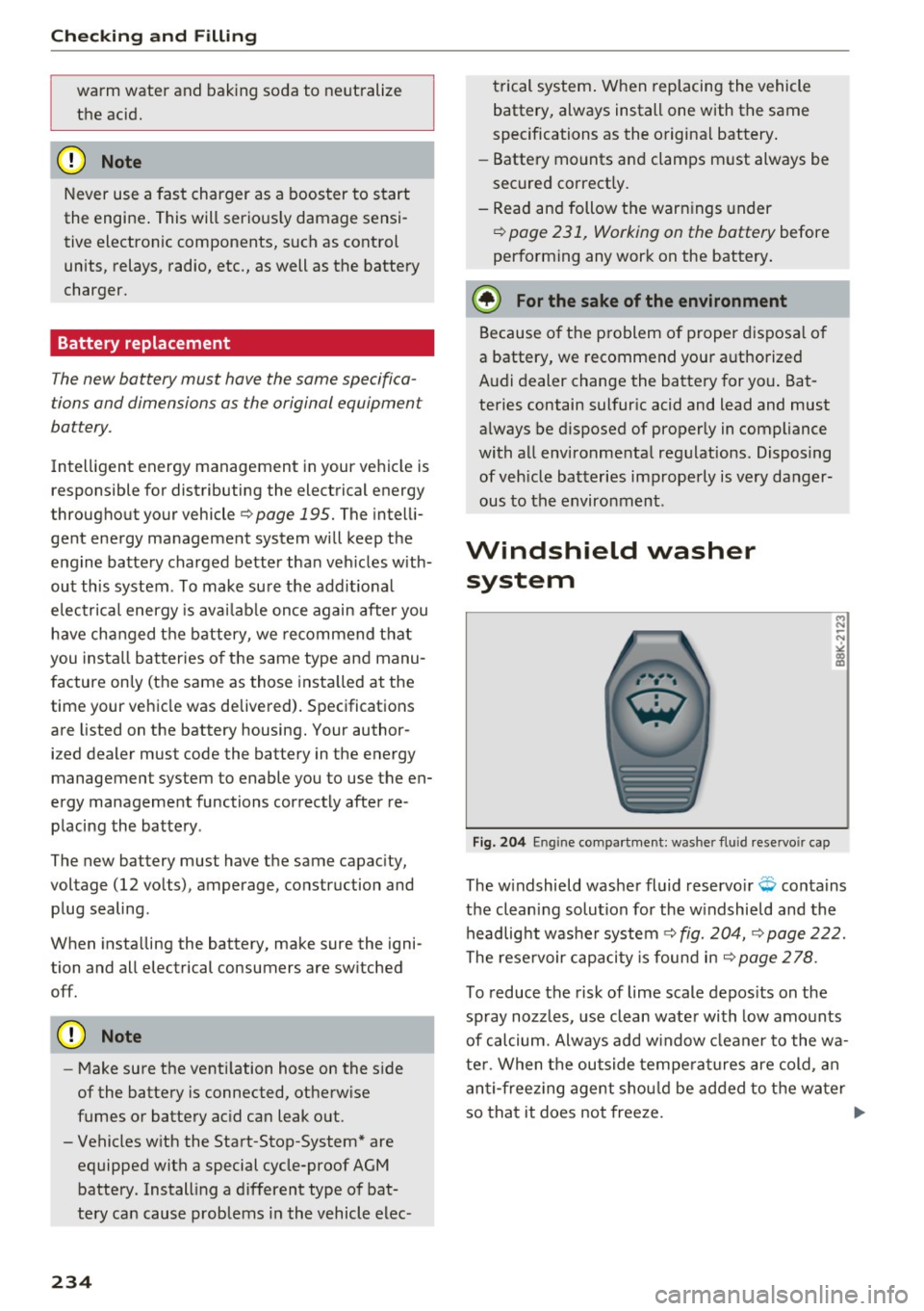
Fig. 204 En gin e compa rt ment: washer fluid rese rvoir cap
The w indshield washer fluid reservo ir Q conta ins
the cleaning solution for the w indshield and the
headlight washe r system ¢
fig. 204, ¢ page 222.
The reservoir capacity is found in
r=> page 2 78 .
To reduce the risk of lime scale depos its on the
spray nozzles, use clean water with low amounts
of calcium. Always add w indow cleaner to the wa
ter . When the outside temperat ures are cold , an
anti-freez ing agent shou ld be added to the water
so that it does not freeze. ..,.
Page 240 of 302
Wheel s
® Mud and snow capability
"M/5" or "M+S" indicates the tire
has characteristics that make it
suitab le for driving on mud and
snow. ~ indicates a winter tire.
@ Composition of the tire cord
and materials
The number of plies indicates the
number of rubberized fabric lay
ers in the tire . In general : the
more layers, the more weight a
tire can carry. Tire manufacturers
must also specify the materials
used in the tire. These include
steel, nylon, polyester and other materials.
@ Ma ximum permitted load
This number indicates the maxi
mum load in kilograms and
pounds that the tire can carry.
@ Uniform tire quality grade
standards for treadwear,
traction and temperature resistance
T readwear, traction and tempera
ture ranges ~
page 253.
@ Running direction
The arrows indicate the running
direction of unidirectional t ires.
You must always follow the speci-
238
fied running direction
~ page 264 .
(8) Maximum permitted
inflation pressure
This number indicates the maxi
mum pressure to which a tire can
be inflated under normal operat
ing condit ions.
Glossary of tire and loading
terminology
Accessory we ight
means the combined weight (in
excess of those standard items
which may be replaced) of auto matic transmission, power steer
ing, power brakes, power win
dows, power seats, radio, and
heater, to the extent that these
items are available as factory -in
stalled equipment (whether in
stalled or not).
Aspect rat io
means the rat io of the height to
the width of the tire in percent.
Numbers of 55 or lower indicate a
low sidewall for improved steer
ing response and better overa ll
handling on dry pavement.
Page 269 of 302
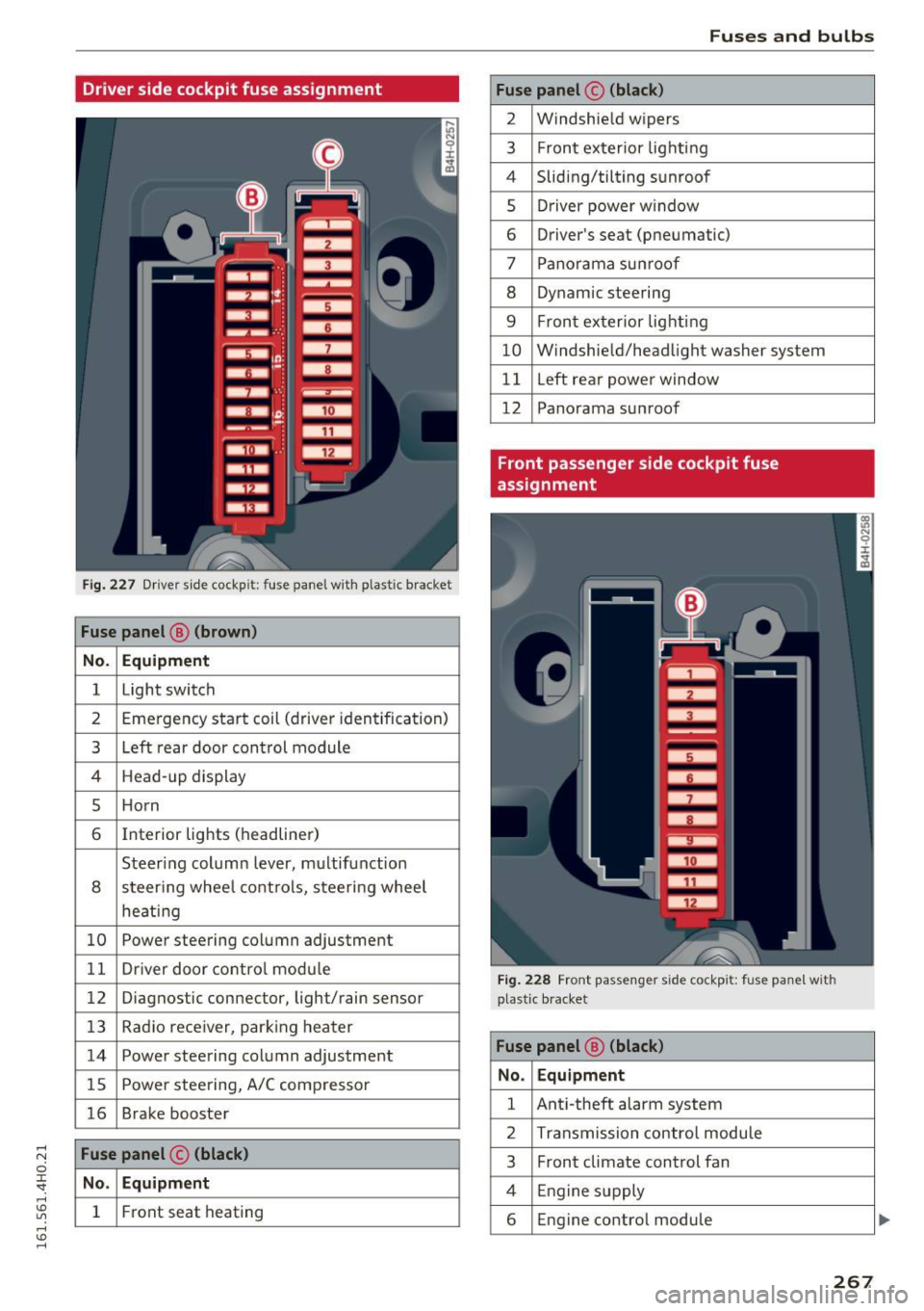
Driver side cockpit fuse assignment
Fig . 227 D river sid e cockpit: fuse panel with plastic bracket
Fuse panel @ (brown )
No . Equipment
1 Light switch
2 Emergency start coil (driver iden tification)
3 Left rear door con trol module
4 Head -up display
5 Ho rn
6 Interior lights (headliner)
Steering column lever, m ultifunction
8 steer ing whee l cont ro ls, steering wheel
heati ng
10 Powe r steering column adjustment
1 1 Dr iver door co ntro l mod ule
12 Diagnostic con nector, light/rain sensor
13 Radio rece iver, par king heater
14 Power steering column adjustment
15 Powe r stee ring, A/C comp resso r
16 Brake booster
Fuse panel © (black)
No . Equipment
1 Front seat heating
Fuses and bulbs
Fuse panel © (black)
2 Windshie ld w ipers
3 F ron t ex terior lig hti ng
4 Sliding/tilting s unroof
5 Dr iver power w indow
6 Driver's seat (pneumatic)
7 Pano rama su nroo f
8 Dynam ic steering
9 F ron t ex terior lig hting
10 W indshie ld/head light washer system
11 Left rea r powe r window
12 Panorama su nroof
Front passenger side cockpit fuse
assignment
Fig. 228 Front passenge r side cockp it: fuse panel with
p last ic b racket
Fuse panel @ (black)
No . Equipment
1 Ant i-theft alarm system
2 Transmission contro l modu le
3 Front climate control fan
4 Engine supply
6 Engine control module
267