height AUDI ALLROAD 2000 Owners Manual
[x] Cancel search | Manufacturer: AUDI, Model Year: 2000, Model line: ALLROAD, Model: AUDI ALLROAD 2000Pages: 306, PDF Size: 9.95 MB
Page 6 of 306
----------------------------------------------TABLE OFCONT ENTS
I GENERAL ILLUSTRATION
General illustration 0 0 0. • • • 8
Warning and indicator lights 10
I SAFETY
FIRST
W elcome ... 0 0 0 •• •• 13
Safety first 0 0
• 0 • 0 0 0 0 • 0 •
13
Safety belts
• . . 0 0 0 • 0 0
14
Airbag system 0 ••••••• 0 0 • • • • • • • 25
Child safety ........ 0 • 0 0 0 0 0 0 0 0 0 44
I CONTROLS AND EQUIPMENT
Keys 0 0 0 0 0 0 0 0 0 0 0 •••• ••••• 0 0 • • 0
56
Power locks 0 0 0 0
Power windows
Mirrors 0 •• 0 0 0 •••
Head restraints
Front seats 0 0 0 •
0.- . 0 0 0 • • 59
69
• •• - •••• 0 ••• 0 72
75
•• 0 •• 0 76
Memory for front seats , .... 0 •• 0 81
Center armrest 0 0 0 0 0 0 0 0 0 •••••• 0 85 Rear
seats 0 0 •• 0 •• 0 • • • • • •
86
Luggage compartment , 0 0 88
Rear facing child seat bench 0 0 0 0 0 92
Ski sack 0 0 0 0 0 0 0 0 0 0 0 0 0 0 0 0.
96
Adjustable steering column
(tilt and telescopic) 0 0 0 0 • 0 0
98
Pedals 0 0 • 0 0 0 0 0 0 0 0 0 0 0 0 0 0 0 0 0 0 0 , 1 02
Parking brake lever 0 • 0 0 0 0 0 0 0 •• 0 1 03
5-speed automatic transmission
(Trptronic ®) 0 0 0 0 0 0 0 0 0 0 • 0 0 0 0 0. 0 • 104
Acoustic park assist
112
Ignition switch 0 0 0 0 0 0 0
1 13
Starting procedures . 0 • • 114
Stopping engine 0 0 0 0 0 0 • • • 115
Instrument cluster 0 0 0 0 0 0 116
Service Interval Display
121
Warning I Indic ator lights 0 0 0 0 0 0 • 122
On Board Diagnostic system 0 0 0 128
Driver information system 0 • 0 • • • 130
Menu display 0 0 0 0 0 0 0 0 0 0 0 0 0
0 131
Rear lid I door open indicator 0 0 0 137
Outside air temp erature 0 • 0 0 0 0 0 0 137 Radio
frequency display 13
8
Auto-Check system 0 0 0 o 0 138
Speed warning . 0 0 0 • 0 0 • • • • 0 • 0 0 144
Tr ip computer 0 0 0 0 0 0 •• 0
146
Switches 0 • 0 •• 0 0 0 0 • 0 0 0 0 148
Ride height adjustment
(4 Level Air Suspension) 0
153
Turn signals,
headlight dimmer switch lever 0 0 156
Cruise control 0 0 0 0 0 0 0 0 0 0 0 0 0 0 0 • • 158
Wiper and washer system 0 ••• 0 0 150
Climate controls 0 0 0 0 0 0 0 0 0 0 0 • 0 152
Power roof 0 0 0 0 0 0 0 • 0 0 0 0 0 • • • • • • 168
Int erior lights, reading lights 171
Luggage compartment light 0 0 0 0 172
Audi Homelink ®
Uni versal Transmitter . 0 0 • • • •
173
Sun visors 00 00 00 00 ... • .. •
177
Sun shade 0 0 0 0 0 0 0 0 •• , • • • ••• 0 0 177
Glo ve compartment
Coat hooks
Ashtray 178
179
180
5
Page 14 of 306
--------------------------------------------------SAFETYRRST
Welcome Dear Audi Owner,
This chapter contains important informa
tion, tips and suggestions on occupant safe
ty.
We've prepared this chapter in order to
summarize what you need to know about
such topics as safety belts, airbags, child
safety, seats for children and infants.
Please make certain that you follow
the suggestions and warnings given
- it's in your own interest and in the
interest of all your passengers.
However, please note, that impor
tant safety information regarding
your vehicle and its operation will
also be found in all other chapters of
this Owner's Manual.
Remember -safety first! Safety
first
Yo ur safety and the safety of your passen
gers shouldn't be left to chance. Advances
in technology have made a variety of fea
tures available to help reduce the risk of in
jur y in an accident. The following is a listing
of just a few of the safety features in your
Audi:
sophisticated safety belts with tension
ers
optimized safety belt geometry through
safety belt ancho rages on front seats,
safety belt height adjustors front seats,
lateral belt adjustment on outer rear
seats,
safety belt guide for the center rear seat
- front airbags
side airbags in the front and rear* seats
- head airbags left and right above the
doors
special seat pan structure
- adjustable steering column
padded kneebar integrated into the dash
board. These
individual safety features, can work
together as a system to help protect you
and your passengers in a wide range of acci
dents. These features can't work as a sys
tem if they are not always properly adjusted
and properly used!
The following sections provide important in
formation about why these features are im
portant, how they work to help protect you
and your passengers and how they must be
adjusted and used to get the greatest bene
fit and reduce the likelihood of injury.
The sections also contain important
WA RNINGS which you and your passen
gers must always heed in order to reduce
the risk of personal injury.
Safety is everybody's responsibil
ity!
1'> ....
Page 21 of 306
SA
FETY RRST-----------------------------------------------------
Fastening the safety belt
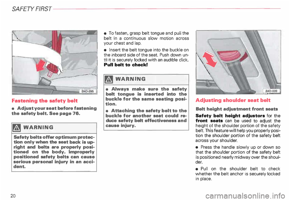
• Adjust your seat before fastening
the safety belt. See page 76.
� WARN ING
Safety belts offer optimum protec
tion only when the seat back is up
right and belts are properly posi
tioned on the body. Improperly
positioned safety belts can cause
serious personal injury in an acci
dent.
20 •
To fasten, grasp belt tongue and pull the
belt in a continuous slow motion across
your chest and lap.
• Insert the belt tongue into the buckle on
the inboard side of the seat. Push down un
til it is securely locked with an audible click.
Pull belt to check!
� WARNING
• Always make sure the safety
belt tongue is inserted into the
buckle for the same seating posi
tion.
• Att aching the safety belt to the
buckle for another seat could re
duce safety belt effectiveness and
cause injury. Adjusting
shoulder seat belt
Belt height adjustment front seats
Safety belt height adjustors for the
front seats can be used to adjust the
height of the shoulder portion of the safety
belt. This feature will help you properly posi
tion the shoulder portion of the safety belt
across your shoulder.
• Press the handle slowly up or down so
that the shoulder portion of the safety belt
is positioned nearly midway over the shoul
der.
• Pull on the shoulder belt to check
whether the belt anchor is securely locked
in place.
Page 23 of 306
SA
FETY RRST---------------------------------------------------
Lateral belt adjustment outer rear
seats
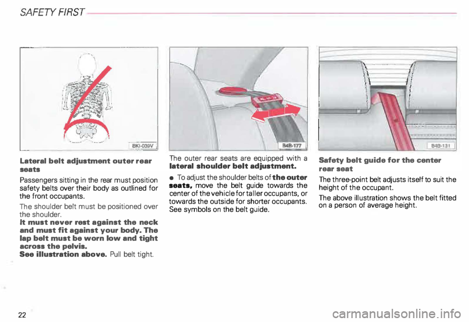
Passengers sitting in the rear must position
safety belts over their body as outlined for
the front occupants.
The shoulder belt must be positioned over
the shoulder.
It must never rest against the neck
and must fit against your body. The
lap belt must be worn low and tight
across the pelvis.
See illustration above. Pull belt tight.
22 The
outer rear seats are equipped with a
lateral shoulder belt adjustment.
• To adjust the shoulder belts of the outer
seats. move the belt guide towards the
center of the vehicle for taller occupants, or
towards the outside for shorter occupants.
See symbols on the belt guide. l
Safety belt guide for the center
rear seat
The three-point belt adjusts itself to suit the
height of the occupant.
The above illustration shows the belt fitted
on a person of average height.
Page 76 of 306
Head
restra ints
Position the head restra ints accor ding to the
occupant's height. Properly positioned head
restra ints, together with the use of safety
belts offer effective protection in most acci
dent situations.
g WARNING
Head restraints are designed to
help reduce injuries in an accident.
Do not drive the vehicle without
the head restraints in place and
properly adjusted.
For maximum protection, the upper edge of
the head restra ints should be at least at
eye level, or high er. ' 848·181
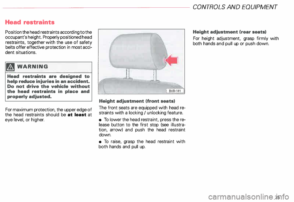
Height adjustment (front seats)
The front seats are equipped with head re
straints with a locking I un locking feature.
• To lower the head restra int, press the re
lease button to the first stop (see illustra
tion, arrow) and push the head restraint
down.
• To raise, grasp the head restraint with
both hands and pull up. CONT
ROLS AND EQUIPMEN T
Height adjustment Crear seats)
For height adjustment, grasp firmly with
both hands and pull up or push down.
75
Page 81 of 306
CONT
ROLS AND EQUIPMENT---------------------
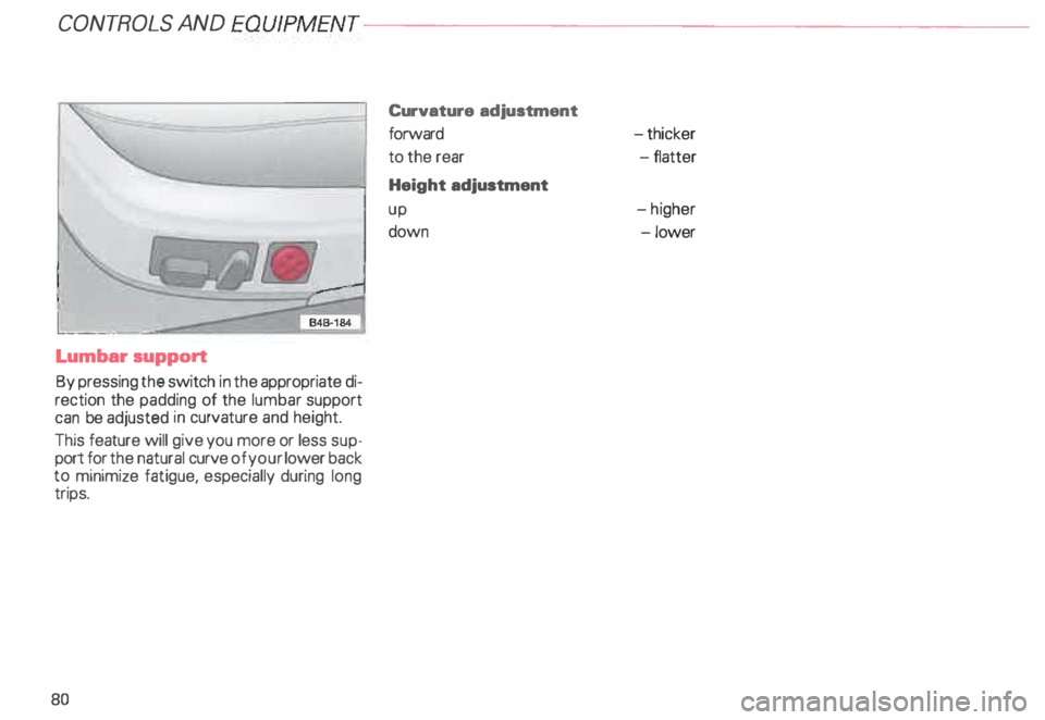
Lumbar
support
By pressing the switch in the appropriate di
rection the padding of the lumbar support
can be adjusted in curvature and height.
This feature will give you more or less sup
port for the natural curve of your lower back
to minimize fatigue, especially during long
trips.
80 Curvature
adjustment
forward
to the rear
Height adjustment
up
down -t
hicker
-f latter
-h igher
-l ower
Page 99 of 306
CONT
ROLS AND EQUIPMENT---------------------
Adjustable steering column (tilt and telescopic)
Manually adjusted steering
wheel
The height and reach of the steering wheel
can be manually adjusted to suit the driver.
The driver's seat should be adjusted first.
Then reposition the steering wheel accord
ing ly.
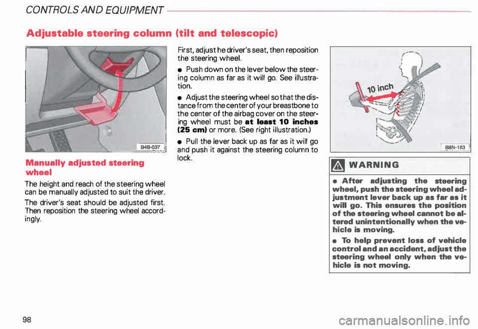
98 First,
adjust he driver's seat, then reposition
the steering wheel.
• Push down on the lever below the steer
ing column as far as it will go. See illustra
tion.
• Adjust the steering wheel so that the dis
tance from the center of your breastbone to
the center of the airbag cover on the steer
ing wheel must be at least 10 inches
(25 em) or more. (See right illustration.)
• Pull the lever back up as far as it will go
and push it against the steering column to
lock. M WARN ING
• After adjusting the steering
wheel, push the stee ring wheel ad
justment lever back up as far as it
will go. This ensures the position
of the steering wheel cannot be al
tered unintentionally when the ve
hicle is moving.
• To help prevent loss of vehicle
control and an accident, adjust the
stee ring wheel only when the ve
hicle is not movi ng.
Page 100 of 306
---------------------CONTROLS
AND EQUIPMEN T
U WARNING continued
• The front seats must not be
pushed too close to the steering
wheel or to the instrument panel.
Never sit closer than 10 inches
(25 em) to the steering wheel.
• If you cannot sit more than
1 0 inches (26 em) from the steer
ing wheel, we recommend that
you investigate whether adaptive
equipment may be available to
help you reach the pedals and in
crease your seating distance from
the stee ring wheel.
• Pointing the stee ring wheel to
ward your face decreases the abil
ity of the supplemental driver's air
bag to protect you in an accident. �
WARNING continued
• Always hold the steering wheel
on the outside of the steering
wheel rim with your hands at the
9 o'clock and 3 o'clock positions
to help reduce the risk of personal
injury if the driver's airbag in
flates.
• Never hold the steering wheel at
the 12 o'clock position or with
your hands at other positions in·
side the steering wheel rim or on
the stee ring wheel hub.
• Holding the steering wheel the
wrong way can cause serious inju
ries to the hands. arms and head if
the driver's airbag inflates. Electrically
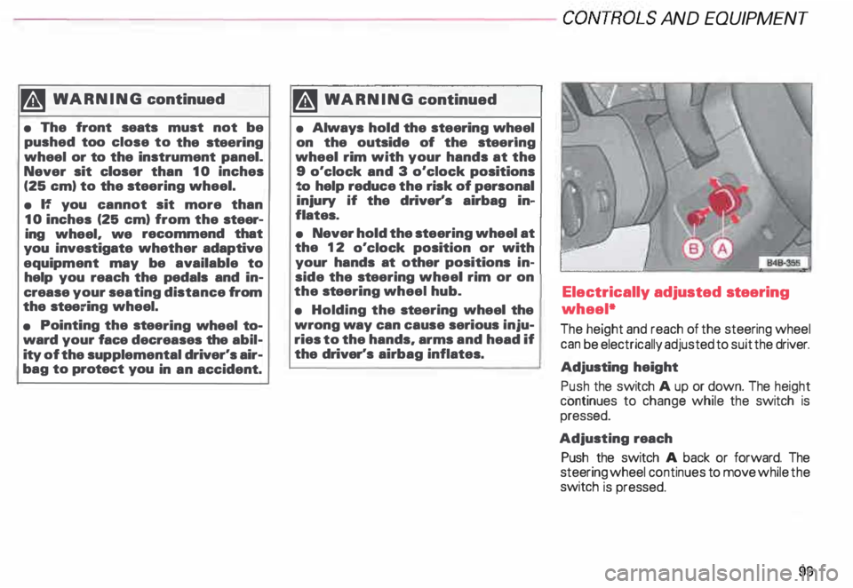
adjusted steering
wheel*
The height and reach of the steering wheel
can be electrically adjusted to suit the driver.
Adjusting height
Push the switch A up or down. The height
continues to change while the switch is
pressed.
Adjusting reach
Push the switch A back or forward. The
steering wheel continues to move while the
switch is pressed.
99
Page 124 of 306
---------------------CONTROLS AND
EQUIPMENT
Electronic
power control• EPC
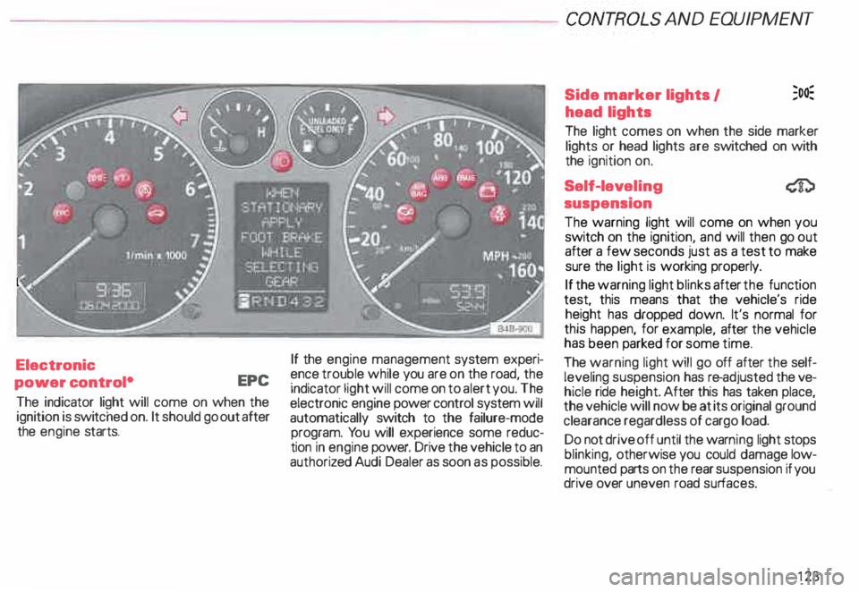
The indicator light will come on when the
ignition is switc hed on. It should go out after
the engine starts. If
the engine management system experi
ence trouble while you are on the road, the
indicator light will come on to alert you. The
electronic engine power control system will
automatically switch to the failure-mode
program. You will experience some reduc
tion in engine power. Drive the vehicle to an
authoriz ed Audi Dealer as soon as possible. Side
marker lights I ;o�
head lights
The light comes on when the side marker
lights or head lights are switched on with
the ignition on.
Self-lev eling
suspension
The warning light will come on when you
switch on the ignition, and will then go out
after a few seconds just as a test to make
sure the light is working properly.
If the warning light blinks after the function
test, this means that the vehicle's ride
height has dropped down. It's normal for
this happen, for example, after the vehicle
has been parked for some time.
The warning light will go off after the self
leveling suspension has re-adjusted the ve
hicle ride height. After this has taken place,
the vehicle will now be at its original ground
clearance regardless of cargo load.
Do not drive off until the warn ing light stops
blinking, otherwise you could damage low
mounted parts on the rear suspension if you
drive over uneven road surfaces.
123
Page 125 of 306
CONTROLS AND
EQUIPMEN T--------------------
If the warning light is flashing, it can also
mean that the vehicle is riding ''too high"
(above the highest level). Once again, do
not drive off until the warning light stops
flashing.
If the .warning light stays on continuous ly,
there 1s a problem with the ride height ad
JUStment system. The light will also come
on continuously if the vehicle is on an ex
treme incline.
Tro uble in the ESP may also cause the warn
ing light to remain on continuously.
A system failure can cause the vehicle to
have too little or too much ground clear
ance. Drive very carefully and slowly to your
nearest authorized Audi dealer and have the
fault corrected.
See page 153 for additional information.
12 4 Electronic Stability
Program {ESP)
The indicator light lights up when the igni
tion is turned on, and it must go out after
about 2 seconds.
When the ESP system is in control mode,
this indicator light will flash while the ve
hicle is being operated.
When you start the engine, the ESP
may shut off for safety reasons. The indica
tor light also turns on to indicate this statu s.
If this should happen, you can reactivate the
ESP by turning the ignition off and then on
� gain. This indicator light will go out, indicat
Ing that the system is once again operating
properly.
If the system is off or is malfunctioning, the
indi cator light will remain on.
Since the ESP system works together with
the ABS system, the ESP indicator light will
also come on if the ABS stops operating. Electronic
immobilizer
�
When you turn on the ignition, the vehicle
key data are automatically scanned. The in
dicator light will come on briefly, indicating
that the data verification procedure has
been acknowledged.
If a non-coded vehicle key was used (for ex
ample a duplic ate key), the control light
goes to a continuous flashing mode. If this
happens, the vehicle cannot be started. See
also page 57