hood open AUDI E-TRON 2019 Owners Manual
[x] Cancel search | Manufacturer: AUDI, Model Year: 2019, Model line: E-TRON, Model: AUDI E-TRON 2019Pages: 310, PDF Size: 81.91 MB
Page 31 of 310
4KE012721BB
Opening and closing
Opening and closing
Central locking
(ee emul ela)
Z\ WARNING
— If you leave the vehicle, switch the ignition
off and take the key with you. This applies
particularly when children remain in the ve-
hicle. Otherwise, children could start the ve-
hicle or operate electrical equipment (such
as power windows), which increases the risk
of an accident.
— Applies to: vehicles with anti-theft alarm
system: When the vehicle is locked from the
outside, no one - especially children - should
remain in the vehicle, because the windows
can no longer be opened from the inside
= page 32, Anti-theft alarm system.
Locked doors make it more difficult for
emergency workers to enter the vehicle,
which puts lives at risk.
All doors and the luggage compartment lid can
be centrally unlocked and locked at once. You can
select in the MMI if the entire vehicle or only the
driver's door should unlock when unlocking the
vehicle > page 30. The turn signals flash twice
when you unlock the vehicle and flash once when
you lock the vehicle. If they do not flash when
locking, then one of the doors, the luggage com-
partment lid, or the hood is not closed complete-
ly.
Depending on the vehicle equipment, you may
have different options for centrally unlocking and
locking your vehicle.
— Vehicle key > page 34
— Sensors in the door handles > page 34
— Lock cylinder on the driver's door > page 32
— Central locking switch inside > page 31
Key / vehicle key
The term “vehicle key” refers to the remote con-
trol key or convenience key*. The convenience
key* is a remote control key with special func-
tions > page 34 and > page 86.
Power closing*
When closing a door or the luggage compart-
ment lid, you only have to Let it fall lightly into
the latch. It then closes automatically > A.
Automatic locking
If you unlock the vehicle but then do not open
any of the doors, the luggage compartment, or
the hood within a short period time, the vehicle
locks again automatically. This feature prevents
the vehicle from being accidentally left unlocked
for along period of time.
Automatic locking (Auto Lock)
The Auto Lock function locks all doors and the
luggage compartment lid once the speed has ex-
ceeded approximately 9 mph (15 km/h).
The vehicle will unlock again if the unlock func-
tion in the central locking switch is pressed, one
of the door handles is pulled, the “P” gear is en-
gaged, or the ignition is switched off.
In the event of a crash with airbag deployment,
the doors will also automatically unlock to allow
access to the vehicle.
Unintentionally locking yourself out
Only lock your vehicle when all of the doors and
the luggage compartment lid are closed and
there is no key in the vehicle. This reduces the
risk of locking yourself out accidentally.
The following features help to reduce the risk of
locking your vehicle key in the vehicle:
— If the driver's door is open, the vehicle cannot
be locked by pressing the f& button on the re-
mote control key or by touching the locking
sensor* on a door.
— If the most recently used convenience key* is
inside the luggage compartment, the luggage
compartment lid will automatically open again
after closing it >@.
— If the convenience key* that was last used is de-
tected inside the vehicle, then the vehicle can-
not be locked from the outside > ©.
29
>
Page 34 of 310
Opening and closing
Mechanically unlocking and locking the
doors
If the central locking fails, you must unlock or
lock the doors separately.
[RAz-0026|
BGA-0027
Fig. 24 Door: mechanically locking
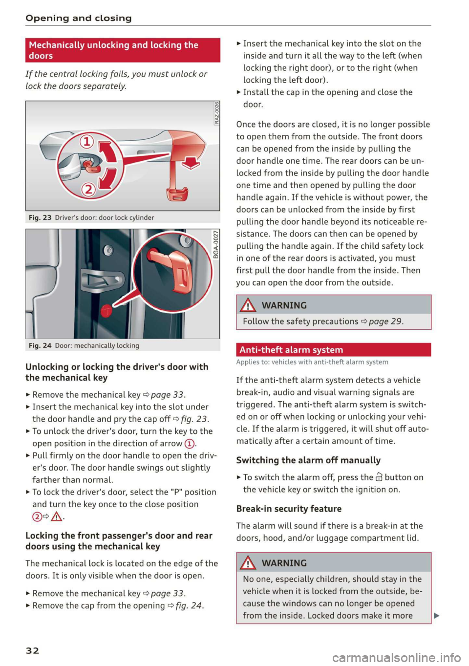
Unlocking or locking the driver's door with
the mechanical key
> Remove the mechanical key > page 33.
> Insert the mechanical key into the slot under
the door handle and pry the cap off > fig. 23.
> To unlock the driver's door, turn the key to the
open position in the direction of arrow @).
> Pull firmly on the door handle to open the driv-
er's door. The door handle swings out slightly
farther than normal.
> To lock the driver's door, select the "P" position
and turn the key once to the close position
@°A.
Locking the front passenger's door and rear
doors using the mechanical key
The mechanical lock is located on the edge of the
doors. It is only visible when the door is open.
> Remove the mechanical key > page 33.
> Remove the cap from the opening > fig. 24.
32
> Insert the mechanical key into the slot on the
inside and turn it all the way to the left (when
locking the right door), or to the right (when
locking the left door).
> Install the cap in the opening and close the
door.
Once the doors are closed, it is no longer possible
to open them from the outside. The front doors
can be opened from the inside by pulling the
door handle one time. The rear doors can be un-
locked from the inside by pulling the door handle
one time and then opened by pulling the door
handle again. If the vehicle is without power, the
doors can be unlocked from the inside by first
pulling the door handle beyond its noticeable re-
sistance. The doors can then can be opened by
pulling the handle again. If the child safety lock
in one of the rear doors is activated, you must
first pull the door handle from the inside. Then
you can open the door from the outside.
ZA WARNING
Follow the safety precautions > page 29.
eae ee)
Applies to: vehicles with anti-theft alarm system
If the anti-theft alarm system detects a vehicle
break-in, audio and visual warning signals are
triggered. The anti-theft alarm system is switch-
ed on or off when locking or unlocking your vehi-
cle. If the alarm is triggered, it will shut off auto-
matically after a certain amount of time.
Switching the alarm off manually
> To switch the alarm off, press the G button on
the vehicle key or switch the ignition on.
Break-in security feature
The alarm will sound if there is a break-in at the
doors, hood, and/or luggage compartment lid.
Z\ WARNING
No one, especially children, should stay in the
vehicle when it is locked from the outside, be-
cause the windows can no longer be opened
from the inside. Locked doors make it more >
Page 54 of 310
Lights and Vision
the windshield wipers go back to the normal
position, or drive faster than 8 mph (12 km/h).
You can also turn the service position on or off in
the MMI:
> Switch the windshield wipers off (position @
=> page 50, fig. 44).
> Applies to: MMI: Select on the home screen:
VEHICLE > Settings & Service > Wiper posi-
tion.
Cleaning the wiper blades
Before cleaning the wiper blades, they must be in
the service position.
> Fold the windshield wiper arm away from the
windshield.
> For information on cleaning, see > table on
page 264.
Replacing the wiper blades
Before removing the wiper blades, they must be
in the service position.
> Fold the windshield wiper arm away from the
windshield.
> Press the locking knob @ on the wiper blade.
Hold the wiper blade firmly.
> Remove the wiper blade from the windshield
wiper arm mount (2).
> Insert the new wiper blade into the mount on
the wiper arm until it clicks into place.
> Place the wiper arm back on the windshield.
> Exit the service position.
Z\ WARNING
— For safety reasons, the windshield wiper
blades should be replaced once or twice
each year.
— Dirty windshield wiper blades can impair vi-
sion, which increases the risk of an accident.
@) Note
— The windshield wipers must only be folded
up when in the service position! Otherwise,
you risk damaging the paint on the hood or
the windshield wiper motor.
— You should not move your vehicle or press
the windshield wiper lever when the wiper
52
arms are folded up from the windshield. The
windshield wipers would move back into
their original position and could damage the
hood and windshield.
G) Tips
— You can also use the service position, for ex-
ample, if you want to protect the windshield
from icing by using a cover.
— You cannot activate the service position
when the hood is open.
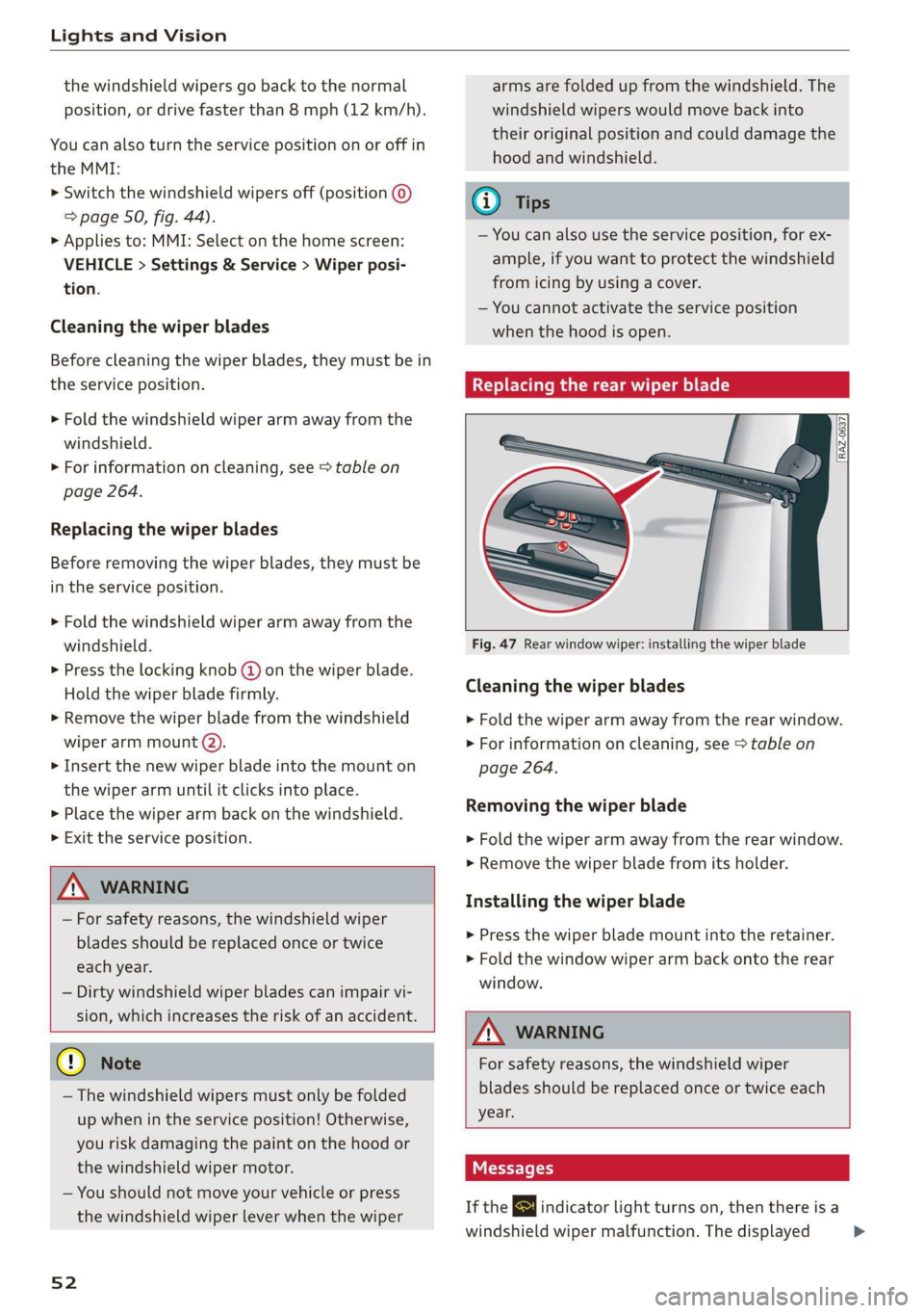
Replacing the rear wiper blade
RAZ-0637| I
Fig. 47 Rear window wiper: installing the wiper blade
Cleaning the wiper blades
> Fold the wiper arm away from the rear window.
> For information on cleaning, see > table on
page 264.
Removing the wiper blade
> Fold the wiper arm away from the rear window.
> Remove the wiper blade from its holder.
Installing the wiper blade
> Press the wiper blade mount into the retainer.
> Fold the window wiper arm back onto the rear
window.
ZA WARNING
For safety reasons, the windshield wiper
blades should be replaced once or twice each
year.
Messages
If the & indicator light turns on, then there is a
windshield wiper malfunction. The displayed
>
Page 78 of 310
Stowing and using
® Note
Beverage containers in the cup holders should
always
have a lid. Otherwise, the liquid inside
could spill and cause damage to vehicle
equipment.
Roof rack
Applies to: vehicles with roof rack
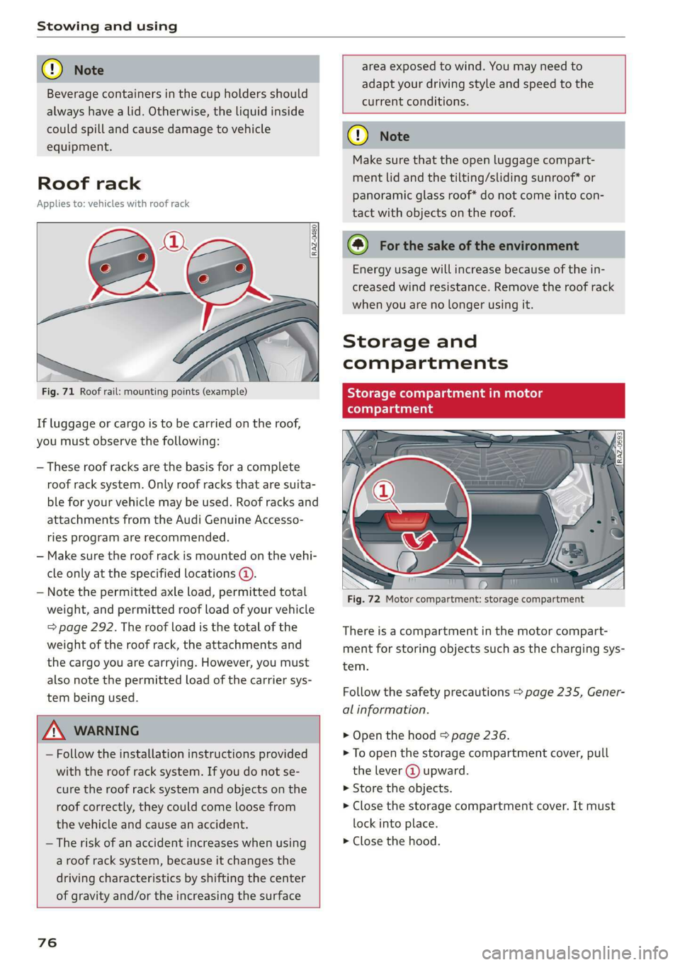
Fig. 71 Roof rail: mounting points (example)
If luggage or cargo is to be carried on the roof,
you must observe the following:
— These roof racks are the basis for a complete
roof rack system. Only roof racks that are suita-
ble for your vehicle may be used. Roof racks and
attachments from the Audi Genuine Accesso-
ries program are recommended.
— Make sure the roof rack is mounted on the vehi-
cle only at the specified locations @.
— Note the permitted axle load, permitted total
weight, and permitted roof load of your vehicle
=> page 292. The roof load is the total of the
weight of the roof rack, the attachments and
the cargo you are carrying. However, you must
also note the permitted load of the carrier sys-
tem being used.
area exposed to wind. You may need to
adapt your driving style and speed to the
current conditions.
ZA WARNING
— Follow the installation instructions provided
with the roof rack system. If you do not se-
cure the roof rack system and objects on the
roof correctly, they could come loose from
the vehicle and cause an accident.
— The risk of an accident increases when using
a roof rack system, because it changes the
driving characteristics by shifting the center
of gravity and/or the increasing the surface
76
o Note
Make sure that the open luggage compart-
ment lid and the tilting/sliding sunroof* or
panoramic glass roof* do not come into con-
tact with objects on the roof.
@) For the sake of the environment
Energy usage will increase because of the in-
creased wind resistance. Remove the roof rack
when you are no longer using it.
Storage and
compartments
Storage compartment in motor
(tonal oy Tada
Fig. 72 Motor compartment: storage compartment
There is a compartment in the motor compart-
ment for storing objects such as the charging sys-
tem.
Follow the safety precautions > page 235, Gener-
al information.
> Open the hood = page 236.
> To open the storage compartment cover, pull
the lever @ upward.
» Store the objects.
> Close the storage compartment cover. It must
lock into place.
> Close the hood.
Page 113 of 310
4KE012721BB
High-voltage system
is the case, authenticate yourself again at the
charging station.
Sytem nas
By setting a timer, you determine when your vehi-
cle should reach the desired charging target.
When the timer is activated, it will be run regu-
larly at the set time. In addition to the charging
target, you can also specify if your vehicle should
be heated or cooled to the temperature set in the
climate control system. You can turn on multiple
timers at the same time. The active timer is indi-
cated by the respective number in © in the upper
section of the display.
> Applies to: MMI: Select on the home screen:
VEHICLE > Charging & Efficiency > Charging.
> When the charging target is displayed, swipe
your finger on the display toward the left.
Multiple timers are displayed that you can set
separately.
> To set a timer, select > in the line for the de-
sired timer.
> Select one ore more days of the week and select
Next.
> Set the desired departure time and select OK.
> To also activate the climate control with a tim-
er, select F.
> To turn ona timer, select CD.
> To activate the timer that is turned on, select
©. A colored bar will turn on in the button.
If the set departure time for the timer is too
soon, the desired charging target may not be
reached.
G) Tips
It is not possible to charge using the timer at
some charging stations.
Advanced charging settings
With the advanced charging settings, you can de-
fine
addresses at which certain charging settings
should apply (for example, charging target, mini-
mum charge). If your vehicle is in the vicinity of
the address, the charging settings will be auto-
matically applied.
> Applies to: MMI: Select on the home screen:
VEHICLE > Charging & Efficiency > Charging >
<2} > Advanced charging settings.
> To define new settings for a certain address, se-
lect +. Follow the instructions in the display.
> To edit existing settings for a certain address,
press the respective button.
> To delete existing settings for a certain ad-
dress, select Z.
Emergency release
You can release the charging unit cover or the
charging connector manually.
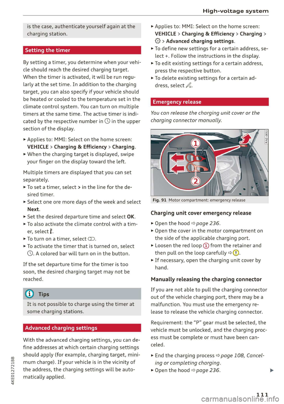
Fig. 91 Motor compartment: emergency release
Charging unit cover emergency release
> Open the hood > page 236.
> Open the cover in the motor compartment on
the side of the applicable charging port.
> Loosen the red loop (@ from the retainer and
then pull on the loop carefully >@.
> If necessary, open the charging unit cover by
hand.
Manually releasing the charging connector
If you are not able to pull the charging connector
out of the vehicle charging port, there may bea
malfunction. You must use the emergency re-
lease to release the vehicle charging connector.
Requirement: the “P” gear must be selected, the
vehicle must be unlocked, and the charging proc-
ess must be complete or must have been can-
celed.
> End the charging process > page 108, Cancel-
ing or completing charging.
> Open the hood & page 236.
111
Page 115 of 310
4KE012721BB
High-voltage system
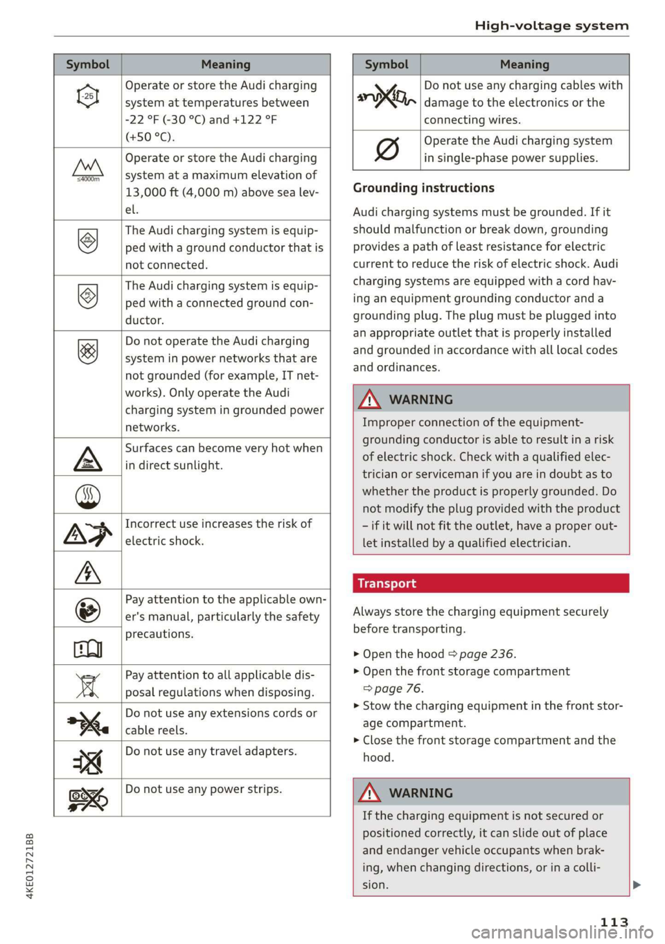
Symbol Meaning Meaning
Operate or store the Audi charging
system at temperatures between
-22 °F (-30 °C) and +122 °F
(+50 °C).
Operate or store the Audi charging
system at a maximum elevation of
4000m_
13,000 ft (4,000 m) above sea lev-
el.
The Audi charging system is equip-
ped with a ground conductor that is
not connected.
©
The Audi charging system is equip-
ped with a connected ground con-
ductor.
&
Do not operate the Audi charging
system in power networks that are
not grounded (for example, IT net-
works). Only operate the Audi
charging system in grounded power
networks.
Surfaces can become very hot when
in direct sunlight.
Incorrect use increases the risk of
electric shock.
Pay attention to the applicable own-
er's manual, particularly the safety
precautions.
Pay attention to all applicable dis-
posal regulations when disposing.
Do not use any extensions cords or
cable reels.
Do not use any travel adapters.
y Do not use any charging cables with
oo, damage to the electronics or the
connecting wires.
Operate the Audi charging system
in single-phase power supplies.
Grounding instructions
Audi charging systems must be grounded. If it
should malfunction or break down, grounding
provides a path of least resistance for electric
current to reduce the risk of electric shock. Audi
charging systems are equipped with a cord hav-
ing an equipment grounding conductor and a
grounding plug. The plug must be plugged into
an appropriate outlet that is properly installed
and grounded in accordance with all local codes
and ordinances.
Z\ WARNING
Improper connection of the equipment-
grounding conductor is able to result in a risk
of electric shock. Check with a qualified elec-
trician or serviceman if you are in doubt as to
whether the product is properly grounded. Do
not modify the plug provided with the product
- if it will not fit the outlet, have a proper out-
let installed by a qualified electrician.
Always store the charging equipment securely
before transporting.
> Open the hood > page 236.
> Open the front storage compartment
=> page 76.
>» Stow the charging equipment in the front stor-
age compartment.
> Close the front storage compartment and the
hood.
Do not use any power strips.
Z\ WARNING
If the charging equipment is not secured or
positioned correctly, it can slide out of place
and endanger vehicle occupants when brak-
ing, when changing directions, or in a colli-
sion. >
113
Page 237 of 310
4KE012721BB
Checking and Filling
Checking and Filling
Motor compartment
General information
Special care is required if you are working in the
motor compartment
For work in the motor compartment, such as
checking and filling fluids, there is a risk of in-
jury, scalding, accidents, and burns. For this
reason, follow all the warnings and general
safety precautions provided in the following in-
formation. The motor compartment is a danger-
ous area in the vehicle. > A.
age component can result in a fatal electric
shock. The components in the high-voltage
system are marked with a warning label which
warns of the high-voltage.
— The voltage level in the high-voltage system
is still dangerous and potentially life-threat-
ening when the ignition is switched off.
— Never perform work on orange high-voltage
cables or on high-voltage components. Only
authorized repair facilities that are certified
may perform work on the high-voltage sys-
tem.
ZA WARNING
— Switch the ignition off.
— Set the parking brake.
— Select the “P” (Park) selector lever position.
— Keep children away from the motor com-
partment.
— Never spill operating fluids in the motor
compartment.
— Avoid short circuits in the electrical system.
— Never open the hood when there is steam or
coolant escaping from the motor compart-
ment, because there is a risk that you could
be burned. Wait until no steam or coolant is
escaping.
— Never open the cap on the coolant reservoir
if the coolant is hot. The cooling system is
under pressure.
— To protect your face, hands, and arms from
hot steam or coolant, cover the cap with a
thick cloth when opening.
— All work on the battery or electrical system
in your vehicle can result in injuries, chemi-
cal burns, accidents, or burns. Because of
this, all work must be performed only by an
authorized Audi dealer or authorized Audi
Service Facility.
— Limit your exposure to chemicals to as short
a time as possible.
ZA WARNING
California Proposition 65 Warning:
— Engine exhaust, some of its constituents,
and certain vehicle components contain or
emit chemicals known to the State of Cali-
fornia to cause cancer and birth defects and
reproductive harm. In addition, certain flu-
ids contained in vehicles and certain prod-
ucts of component wear contain or emit
chemicals known to the State of California
to cause cancer and birth defects or other
reproductive harm.
— Battery posts, terminals and related acces-
sories contain lead and lead compounds,
chemicals known to the State of California
to cause cancer and reproductive harms.
Wash hands after handling.
ZA\ WARNING
The voltage in the high-voltage system is life-
threatening. Touching a damaged high-volt-
() Note
When filling fluids, be sure not to add any flu-
ids to the wrong reservoirs. Otherwise, severe
malfunctions and damage will occur.
@) For the sake of the environment
You should regularly check the ground under
your vehicle in order to detect leaks quickly. If
there are visible spots from oil or other fluids,
bring your vehicle to an authorized Audi deal-
er or authorized Audi Service Facility to be
checked.
235
Page 238 of 310
Checking and Filling
Opening and closing the hood
The hood is released from inside the vehicle.
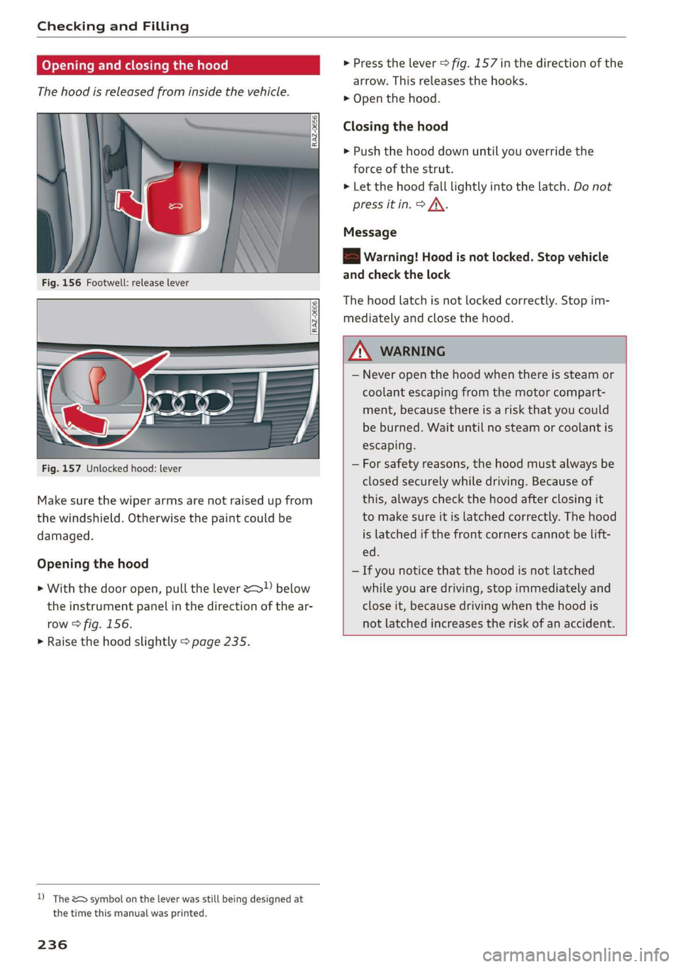
Fig. 156 Footwell: release lever
RAZ-0606
Fig. 157 Unlocked hood: lever
Make sure the wiper arms are not raised up from
the windshield. Otherwise the paint could be
damaged.
Opening the hood
> With the door open, pull the lever > below
the instrument panel in the direction of the ar-
row > fig. 156.
> Raise the hood slightly > page 235.
D) The &> symbol on the lever was still being designed at
the time this manual was printed.
236
> Press the lever > fig. 157 in the direction of the
arrow. This releases the hooks.
> Open the hood.
Closing the hood
> Push the hood down until you override the
force of the strut.
> Let the hood fall lightly into the latch. Do not
press it in. > /\.
Message
EB warning! Hood is not locked. Stop vehicle
and check the lock
The hood latch is not locked correctly. Stop im-
mediately and close the hood.
ZA WARNING
— Never open the hood when there is steam or
coolant escaping from the motor compart-
ment, because there is a risk that you could
be burned. Wait until no steam or coolant is
escaping.
— For safety reasons, the hood must always be
closed securely while driving. Because of
this, always check the hood after closing it
to make sure it is latched correctly. The hood
is latched if the front corners cannot be lift-
ed.
— If you notice that the hood is not latched
while you are driving, stop immediately and
close it, because driving when the hood is
not latched increases the risk of an accident.
Page 240 of 310
Checking and Filling
the vehicle will be operated. If the coolant addi-
tive percentage is too low, the coolant can freeze
and cause damage.
Coolant Freeze protec-
additive tion
Warm min. 40% min. -13 °F
regions max. 45% (25°)
Cold min. 50% max. -40 °F
regions max. 55% (-40 °C)
@) Note
— Before winter weather begins, have an au-
thorized Audi dealer or authorized Audi
Service Facility check if the coolant additive
in your vehicle matches the percentage ap-
propriate for the climate. This is especially
important when driving in colder climates.
— If the appropriate coolant additive is not
available in an emergency, do not add any
other additive. Using other additives in-
creases the risk of damage. If this happens,
only use water and restore the correct mix-
ture ratio with the specified coolant additive
as soon as possible.
— Only refill with new coolant.
— Radiator sealant must not be mixed with
the coolant.
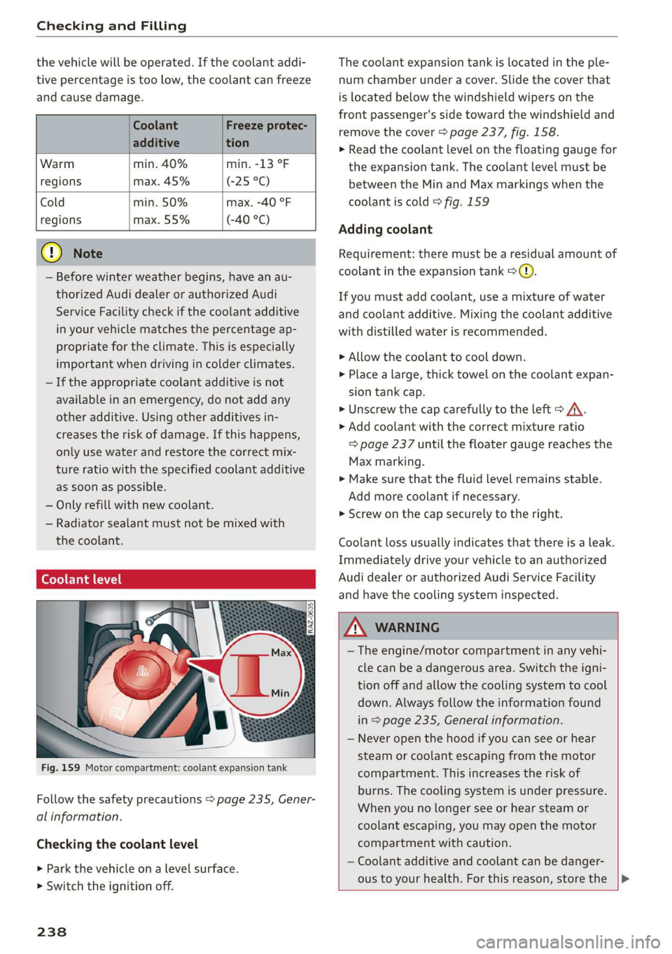
Coolant level
Fig. 159 Motor compartment: coolant expansion tank
Follow the safety precautions > page 235, Gener-
al information.
Checking the coolant level
> Park the vehicle on a level surface.
> Switch the ignition off.
238
The coolant expansion tank is located in the ple-
num chamber under a cover. Slide the cover that
is located below the windshield wipers on the
front passenger's side toward the windshield and
remove the cover > page 237, fig. 158.
> Read the coolant level on the floating gauge for
the expansion tank. The coolant level must be
between the Min and Max markings when the
coolant is cold > fig. 159
Adding coolant
Requirement: there must be a residual amount of
coolant in the expansion tank >@).
If you must add coolant, use a mixture of water
and coolant additive. Mixing the coolant additive
with distilled water is recommended.
> Allow the coolant to cool down.
> Place a large, thick towel on the coolant expan-
sion tank cap.
> Unscrew the cap carefully to the left > A\.
> Add coolant with the correct mixture ratio
=> page 237 until the floater gauge reaches the
Max marking.
> Make sure that the fluid level remains stable.
Add more coolant if necessary.
> Screw on the cap securely to the right.
Coolant loss usually indicates that there is a leak.
Immediately drive your vehicle to an authorized
Audi dealer or authorized Audi Service Facility
and have the cooling system inspected.
Z\ WARNING
— The engine/motor compartment in any vehi-
cle can be a dangerous area. Switch the igni-
tion off and allow the cooling system to cool
down. Always follow the information found
in > page 235, General information.
— Never open the hood if you can see or hear
steam or coolant escaping from the motor
compartment. This increases the risk of
burns. The cooling system is under pressure.
When you no longer see or hear steam or
coolant escaping, you may open the motor
compartment with caution.
— Coolant additive and coolant can be danger-
ous to your health. For this reason, store the |>
Page 301 of 310
4KE012721BB
Index
Mechanically unlocking
Opening and closing.................0.
Opening and closing with foot motion..... 37
Power opening and closing.............. 36
Lumbar'support waco: 2s ees ev wees ee eerwe as 56
M
Maintenance « sige a + cewe «2 cee ge ewe a es 286
Maintenance intervals « nw. 6 i gic ae cere a 242
Manually releasing the charging connector. 111
Manually releasing the charging unit cover. 111
Map
Changing the scale...........00.e eee 198
Display cosee + a ssowsoe = semais 2 4 onaesms x aerate & 200
Operating ........ 0... ce eee eee eee 199
Setting the destination................ 198
Map preview.............-.0 2000-0 eee 197
Map update................ 020. e ee eee 204
QNUIME seers « « seers & e eee 5 2 eS & HEE FS 205
SD card/USB connection............... 205
Massage TUNCtiON. « ssa ss esi se owe ¥ 6 orem 56
Front... 2... eee eee eee eee 57
Matrix LED headlights.................-. 45
Mechanical:-key’. « « esscos ss caune oo aware © v cere 33
Medicis: 2 = acess: a © vonses a @ mewn 2 © cose 217,221.
Drives... ee 217
Supported formats...............0005 227
Media
center................ eee eee ee 222
Memory card
SD card reader (MMI) « « ewes sc ees an es 217
Supported types and formats........... 227
Mennory functioniie: « 2 sews x ¢ amen 5 meee eo: 63
Menu language
refer to Setting the language........... 231
Messagesi. « eciis + wean a 6 mans w 6 aaa oo we 178
Mirror cOMpaSS « wes + ¢ esas so sees eo eee vs 53
Mirrors
Adjusting exterior mirrors............0-. 48
Dimming................0 00002 e eee 49
Nanlity MUFROT sxc 2 = mown 2 seers « o eeoes gee 50
MMI
refer to Multi Media Interface........... 17
Mobile device
refer to Telephone...........-.0eee ee 169
Mobile phone network
Connection settings.................. 182
Motor compartment
Opening and closing the hood.......... 236
OVERVIEW eeu 3 2 soupy < @ emiees ¢ esate Go ee 237
Safety precautions: . sicsc. sven 2s wen ae 235
Storage compartment..............-... 76
Mountain passes... 0... ... eee eee eee 96
Mountaininoads:. « « secs « « erence» 2 sestane » 6 soene 96
Multifunction steering wheel
Buttons... ..... cee ee ee 12,26
Operating: < = ssn < : seen es sonnet dome s ee 12
Programming buttons.................. 26
Voice recognition system............... 24
Multi Media Interface................085 17
Menus and symbols.............00+-00- 18
Operating’s « « wss6 s secu = s sees & & wens 2 15,18
Switching the displays on or off.......... 17
Mutting (Mute) secs se ences oe ences oo cena oo eee 26
MYAUGI s « scimvs «6 eens 2s ents 2 & eee 2 weceale 27
myAudi navigation................. 193, 197
N
NarrOW APES s « eewn ss weue swoon as wee ae 146
Natural
leather care and cleaning......... 266
Navigation ....... 66... cee cece eee eee 193
Better rout@scs << sews eo es do eg e cae 206
Calli gprs so meena « i soieasen © o onewowe mraten wo 197
Changing the scale................0-. 197
also:referto Map: « wim + x wows 2 neee se ne 199
Navigation database
Version'information . . . ico ce caren so ens 233
Navigation (instrument cluster).......... 201
NHTSAc: = swiss « = seu = ¢ sous 4 x teats & Sees g 288
Night vision aSsist'; « sean 5 «wean ss ween avi 13)
Cleaning the camera...............00. 264
Notification:center’s ¢ sas 3 ¢ caw 2s gauss wars 19
O
OdOMCters cacy « & cees 5 o exw 5 ¢ eee 7 e ews 13
RESCUING fests 6 & srecine 6 o aiorsus 6 @ nureons wo eaNUEDK 13
Office address
refer to Business address.............. 202
Offroad
refer to Offroad driving...............+- 96
Offroad driving...............e eee e eee 96
OFF (climate control system) .............. 82
299