User AUDI E-TRON 2021 User Guide
[x] Cancel search | Manufacturer: AUDI, Model Year: 2021, Model line: E-TRON, Model: AUDI E-TRON 2021Pages: 308, PDF Size: 83.91 MB
Page 99 of 308
4KE012721BF
Driving
be delayed. Other factors that could temporarily
increase the response time of the brakes include:
— Wet conditions
— Low temperatures, ice, and snow
— Roads covered in salt
— Dirty brake pads
Corrosion
Corrosion may form on the brake rotors if there is
no heavy braking, if the vehicle is not driven for
long periods of time, or if the vehicle is not driv-
en
frequently or for long distances. In this case,
braking heavily several times while driving at
high speeds can clean the brake rotors > A\.
To do this, select the “N” gear so that recupera-
tion is not used for braking.
Brake pads
New brake pads do not achieve their full braking
effect during the first 500 mi (800 km). They
must be “broken in” first. However, you can com-
pensate for the slightly reduced braking force by
pressing firmly on the brake pedal. Avoid heavy
braking during the break-in period.
Because recuperation is also used for braking, the
break-in period for new brake pads is 500 miles
(800 km).
Brake pad wear depends largely on the way the
vehicle is driven and on operating conditions.
Brake pad wear increases when driving frequently
in the city or short distances or when using a very
sporty driving style.
Automatic post-collision braking system
The automatic post-collision braking system can
help to reduce the risk of sliding and of addition-
al collisions after an accident. If the airbag con-
trol module detects a collision, the vehicle is
braked by the ESC.
The vehicle does not brake automatically if one of
the following occurs:
— The driver presses the accelerator pedal, or
—The braking force generated by the pressed
brake pedal is greater than the braking force
that would be initiated by the system
— The ESC, the brake system, or the vehicle elec-
trical system is not functioning
ZA WARNING
— Only apply the brakes for the purpose of
cleaning the brake system when road and
traffic conditions permit. You must not en-
danger other road users and increase the
risk of an accident.
— Due to the risk of injury, only have an au-
thorized Audi dealer or authorized Audi
Service Facility work on the brake system.
Incorrect repairs could impair the function.
— Never let the vehicle roll while the drive sys-
tem is switched off because this increases
the risk of an accident.
— During automatic braking maneuvers, the
brake pedal may move downward automati-
cally. To reduce the risk of injury, do not
place your foot under the brake pedal.
CG) Note
— Never let the brakes “rub” by pressing the
pedal lightly when braking is not actually
necessary. This can cause the brakes to over-
heat and increases braking distance and
causes wear.
— Observe the important information for driv-
ing downhill > page 100. This especially ap-
plies when towing a trailer.
@ Tips
— If you retrofit your vehicle with a front spoil-
er, wheel covers or similar items, make sure
that the air flow to the brakes is not ob-
structed. Otherwise the brake system can
overheat.
— Also refer to the information about brake
fluid > page 236.
We Te(4
EG / @ Brakes: malfunction! Safely stop ve-
hicle
There is a malfunction in the brake system. If
BS / Gana B also turn on, there is a malfunc-
tion in the ABS, ESC, and braking distribution. If >
97
Page 103 of 308

4KE012721BF
Driving
@ For the sake of the environment
Avoid actions that are damaging to the envi-
ronment. Show respect for the natural envi-
ronment and remain on marked routes.
@ Tips
Clean your vehicle after driving offroad. Dirt
and stones falling off your vehicle can affect
other road users.
Driving through water
If you must drive through water, follow these in-
structions:
— Check the stability of the ground, the current,
and the water depth. If the ground is unstable,
there is a strong current, or there are waves,
the water must only reach up to the lower edge
of the body at the most.
— Drive carefully and no faster than at walking
speeds to prevent the front of the vehicle from
creating waves, because they could splash
above the lower edge of the body. Oncoming
vehicles could also create waves.
— Do not stop the vehicle while in the water.
— Drive in reverse.
— Do not switch off the drive system.
Z\ WARNING
After driving through water, press the brake
pedal carefully to dry the brakes so that the
full braking effect will be restored.
@) Note
Vehicle components such as the motor, drive
system, suspension, or electrical system can
be severely damaged by driving through wa-
tele
@) Tips
If possible, avoid driving through salt water
because it increases the risk of corrosion. Use
fresh water to clean any vehicle components
that come into contact with salt water.
Hill descent assist
Applies to: vehicles with hill hold assist
The “& button is located in the function bar on
the lower display. It lights up when the system is
turned on.
Hill descent assist can assist you when driving
down hills by maintaining a constant vehicle
speed by automatically braking all four wheels.
You can adjust the speed using the accelerator
and brake pedals. The regulation depends on the
hill and the vehicle speed.
> Switching on: press e
> Switching off: press “ again.
Active regulation
Regulation begins shortly after you start driving
and is possible at speeds up to approximately 19
mph (30 km/h) and on hills that have an approxi-
mately 6-60% grade. If these conditions are met,
regulation will be activated and the indicator
light will turn on.
Ready mode
If one of the requirements for active regulation is
not met, the system will be in ready mode. The
a indicator light will turn on. Once the require-
ments are met again, the system will be able to
provide active regulation again.
ZA\ WARNING
— Be ready to apply the brakes at all times
when using the hill hold assist.
— Always adjust the speed to the visibility,
weather, road, and traffic conditions. The
system cannot replace the driver's atten-
tion.
— The system cannot maintain a constant vehi-
cle speed in all situations, for example when
on smooth or slippery ground. This can in-
crease the risk of an accident.
G) Tips
If you select the Audi drive select* offroad
mode, hill descent assist will switch on.
101
Page 115 of 308

4KE012721BF
High-voltage system
Depending on the selected view > page 12, the
following information about the charging process
is displayed in the instrument cluster:
— Gv: range
—&: remaining charging time until the charging
process is complete
— 2): current battery charge level
—Q: date and time of when the charging process
was completed
—&: charging speed (additional range per hour)
—4: charging power (depends on the selected
power source)
To access the charging process information at a
later time, select in the instrument cluster: Vehi-
cle functions tab > EE] button > Charging.
Ending the charging process
You can interrupt the charging process at any
time.
— Unlock the vehicle. In vehicles with a conven-
ience key*, the convenience key only needs to
be near the charging port door.
— Press the center of the button @.
— Remove the charging connector. If the charging
connector is not removed within 30 seconds, it
will automatically relock and the charging proc-
ess may continue.
— After removing the charging connector, the
charging port door will close automatically;
otherwise, press on the center of the button @
to close the charging port door.
— Disconnect the charging cable from the power
supply if necessary or return it securely to the
charging station.
— Install the protective caps on the charging ca-
ble again.
—If you are transporting the charging cable in
the vehicle, store it securely > page 119.
If the charging connector cannot be disconnected
from the vehicle, perform the following steps in
the order listed and try again to disconnect the
charging connector:
— Switch the ignition on/off.
— Lock/unlock the vehicle.
— Make sure the auxiliary air conditioning is not
activated > page 87.
If the charging connector still cannot be discon-
nected, you must unlock it manually > page 116.
If you cannot disconnect the charging connector
from the charging station, authenticate yourself
again at the charging station and then try again
to disconnect the charging connector. If you still
cannot disconnect the charging connector from
the charging station, contact the charging sta-
tion operator.
Z\ WARNING
—When closing the charging port door, make
sure the area where the door is closing is
clear to reduce the risk of injury.
— Do not disconnect the charging cable from
the socket or the vehicle charging port while
the vehicle is charging. End the charging
process before removing the charging cable
from the socket in order to reduce the risk of
damaging the connector contacts from
sparks.
— Never drive with the charging port door
open. An open charging port door could hit
other road users, which increases the risk of
injury.
— Ifa charging unit is damaged, the vehicle
must not be charged at the damaged charg-
ing port or at the charging port on the other
side* to reduce the risk of injury.
— If the charging unit is damaged or the
charging port door cannot close or is miss-
ing, drive immediately to an authorized Audi
dealer or authorized Audi Service Facility
and have the malfunction corrected to re-
duce the risk of injury.
@) Note
— If you drive with the charging unit open,
both the charging port door and the elec-
tronics installed behind it could be dam-
aged. Check each time after charging if the
port door is locked before you start driving
the vehicle.
— Applies to: vehicles with charging ports on
the driver and front passenger’s side: Never
attempt to charge the vehicle using both
113
>
Page 131 of 308
4KE012721BF
Assist systems
Assist systems
General information
Sra eel delay
ZA\ WARNING
— As the driver, you are always completely re-
sponsible for all driving tasks. The assist
systems cannot replace the driver's atten-
tion. Give your full attention to driving the
vehicle, and be ready to intervene in the
traffic situation at all times.
— Activate the assist systems only if the sur-
rounding conditions permit it. Always adapt
your driving style to the current visual,
weather, road, and traffic conditions.
— Loose objects can be thrown around the ve-
hicle interior during sudden driving or brak-
ing maneuvers, which increases the risk of
an accident. Store objects securely while
driving.
— For the assist systems to be able to react
correctly, the function of the sensors and
cameras must not be restricted. Note the in-
formation on sensors and cameras
= page 130.
@ Tips
— Pay attention to applicable local regulations
relating to driving tasks, leaving space for
emergency vehicles, vehicle distance, speed,
parking location, wheel placement, etc. The
driver is always responsible for following
the laws that are applicable in the location
where the vehicle is being operated.
— You can cancel a steering or braking inter-
vention by the system by braking or acceler-
ating noticeably, steering, or deactivating
the respective assist system.
— Always check the assist systems settings be-
fore driving. The settings could have been
changed, for example by other drivers or by
using another user.
System limitations
ZA\ WARNING
—The use of an assist system cannot over-
come the natural laws of physics. A collision
cannot be prevented in certain circumstan-
ces.
— Warnings, messages, or indicator lights may
not be displayed or initiated on time or cor-
rectly, for example, if vehicles are approach-
ing very fast.
— Corrective interventions by the assist sys-
tems, such as steering or braking interven-
tions, may not be sufficient or they may not
occur. Always be ready to intervene.
@) Tips
— Due to the system limitations when detect-
ing the surrounding area, the systems may
warn or intervene unexpectedly or too late
in certain situations. The assist systems may
also interpret a driving maneuver incorrectly
and then warn the driver unexpectedly.
— The systems may not function as expected
in unusual driving situations, such as driving
offroad, on unpaved roads, on loose ground,
on inclines, or on grooves in the road.
— The systems may not function correctly in
unclear traffic situations, such as turning
lanes, exit ramps, construction zones, rises
or dips that obstruct visibility, intersections,
toll stations, or city traffic.
— The detection of the surrounding area can
be limited, for example by vehicles driving
ahead or by rain, snow, heavy spray, or light
shining into the camera.
—In trailer mode, some assist systems may be
limited, may not react as usual, or may be
unavailable. Please refer to the instructions
for towing a trailer located in > page 126.
— The steering wheel touch recognition may
be limited when you wear gloves. Steering
intervention requests from the steering as-
sist systems may occur more frequently.
— If accessories have been mounted on the
steering wheel, the steering assist systems
may
be limited. The frequency of steering
129
>
Page 140 of 308
Driving information
— The silhouette in the display appears in-
complete or interrupted, for example be-
cause the pedestrian is partially behind a
vehicle or an animal is partially covered by
tall grass.
— Never attempt to swerve around animals if
doing so would endanger you or other road
users.
G) Tips
— Even though the system evaluates the
shape and heat given off by all detected ob-
jects, there are limits to the system. There
may be false warnings.
— For technical reasons, the image pauses in
split second intervals.
Scale emo
Applies to: vehicles with night vision assist
The system can be switched on and off in the
MMI & page 132.
> The AUTO light function must be selected for
the night vision assist to automatically activate
when it is dark.
> Switch on the low beams manually to activate
night
vision assist immediately. To do so,
press @) on the light switch module and select
When activated, the % tab appears in the instru-
ment cluster.
> Select in the instrument cluster: $1 tab
G) Tips
When the night vision assist tab is selected in
the instrument cluster and the low beams are
switched off, the thermal image display dis-
appears only after you have exited the tab.
138
Marking and warning
Applies to: vehicles with night vision assist
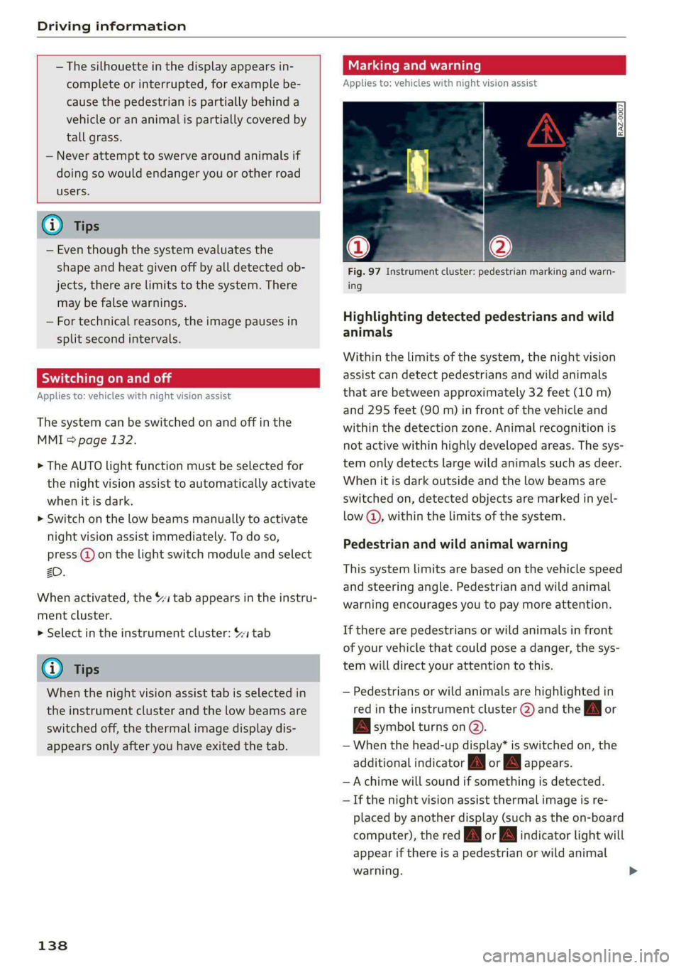
Fig. 97 Instrument cluster: pedestrian marking and warn-
ing
Highlighting detected pedestrians and wild
animals
Within the limits of the system, the night vision
assist can detect pedestrians and wild animals
that are between approximately 32 feet (10 m)
and 295 feet (90 m) in front of the vehicle and
within the detection zone. Animal recognition is
not active within highly developed areas. The sys-
tem only detects large wild animals such as deer.
When it is dark outside and the low beams are
switched on, detected objects are marked in yel-
low @), within the limits of the system.
Pedestrian and wild animal warning
This system limits are based on the vehicle speed
and steering angle. Pedestrian and wild animal
warning encourages you to pay more attention.
If there are pedestrians or wild animals in front
of your vehicle that could pose a danger, the sys-
tem will direct your attention to this.
— Pedestrians or wild animals are highlighted in
red in the instrument cluster (2) and the J or
BAN symbol turns on @.
— When the head-up display* is switched on, the
additional indicator [AM or EM appears.
—Achime will sound if something is detected.
—If the night vision assist thermal image is re-
placed by another display (such as the on-board
computer), the red A or A indicator light will
appear if there is a pedestrian or wild animal
warning.
Page 158 of 308
Driver assistance
ready to provide warnings after a short time, and
it will only become active again later.
If the driver does not take over steering, the lane
departure warning will no longer be ready to pro-
vide warnings. If the vehicle is equipped with
emergency assist and it is ready to function, it
will be activated > page 164.
Behavior when a turn signal is active
Applies to: vehicles with side assist: The system
will not warn you if you activate a turn signal be-
fore crossing the lane marker line. In this case, it
assumes that you are changing lanes intentional-
ly.
Applies to: vehicles with side assist: If the turn
signal is activated, the lane departure warning is
ready, and a lane change has been classified as
critical by the lane departure warning due to
vehicles traveling beside you or due to approach-
ing vehicles, then a noticeable corrective steering
movement will occur shortly before exiting the
lane. This will attempt to keep your vehicle in the
lane.
ZA\ WARNING
— Observe the safety precautions and note the
limits of the assist systems, sensors, and
cameras > page 129.
— The system warns the driver that the vehicle
is leaving the lane using corrective steering.
The driver is always responsible for keeping
the vehicle within the lane.
— Corrective steering may not occur at all in
certain situations, such as during heavy
braking. Always be ready to intervene.
@ Tips
— Always keep your hands on the steering
wheel so you can be ready to steer at any
time. The driver is always responsible for
adhering to the regulations applicable in
the country where the vehicle is being oper-
ated.
156
— The system does not provide any corrective
steering or steering wheel vibrations if it de-
tects that you are passing another vehicle.
PN Ut ae MAMLUK (Slade RN eal Lar)
Applies to: vehicles with lane departure warning
The additional warning using vibration in the
steering wheel can be switched off or on. The set-
tings depend on the vehicle equipment.
— Applies to MMI: Select on the home screen: VE-
HICLE > Driver assistance > (3) > Lane depar-
ture warning > Vibration warning.
Messages
Applies to: vehicles with lane departure warning
ray or is displayed when there is a malfunc-
tion, the lane departure warning and lane guid-
ance functions of the adaptive cruise functions
may be unavailable or limited.
A message that indicates the cause and possible
solution
may appear with some displays. The
weather conditions may be too poor or the cam-
era may be covered. Clean the area in front of the
camera > page 131 and try to turn on the sys-
tems again later.
If the malfunction remains, drive to an author-
ized Audi dealer or authorized Audi Service Facili-
ty immediately to have the malfunction correct-
ed.
Audi pre sense
Introduction
Applies to: vehicles with Audi pre sense
Within the limits of the system, the Audi pre
sense functions can initiate measures in certain
driving situations to protect the vehicle occu-
pants and other road users. Depending on the ve-
hicle equipment, various Audi pre sense systems
may
be installed:
Page 164 of 308
Driver assistance
— The coverage areas of the sensors > fig. 114
are diagrams and do not represent a true-
to-scale image of the sensor ranges.
— The system complies with United States FCC
regulations and ISED regulations
> page 288.
Adjusting side assist
Applies to: vehicles with side assist
The system can be switched on and off in the
MMI = page 132. If the system is activated, the
displays will turn on briefly when the ignition is
switched on.
Adjusting the brightness
You can adjust the brightness of the display in
the exterior mirror. The settings depend on the
vehicle equipment.
> Applies to: MMI: Select on the home screen:
VEHICLE > Driver assistance > (<23) > Side as-
sist > Brightness.
The display brightness is automatically adapted
to the ambient light. If the automatic adaptation
has already reached the upper or lower limit, no
change will be apparent when the setting is
changed, or it will only become visible when the
ambient light changes. Adjust the brightness to a
level where the display in the information stage
will not disrupt your view ahead. If you change
the brightness, the display will briefly show the
brightness level in the information stage.
Messages
Applies to: vehicles with side assist
rig or Bg is displayed when there is a malfunc-
tion, the side assist and exit warning system
functions may be unavailable or may be limited.
A message that indicates the cause and possible
solution may appear with some displays. The
weather conditions may be too poor or a sensor
may be covered. Clean the sensor area at the rear
corners of the vehicle > page 131, fig. 93 and try
to turn the systems on again later.
If the malfunction remains, drive to an author-
ized Audi dealer or authorized Audi Service Facili-
162
ty immediately to have the malfunction correct-
ed.
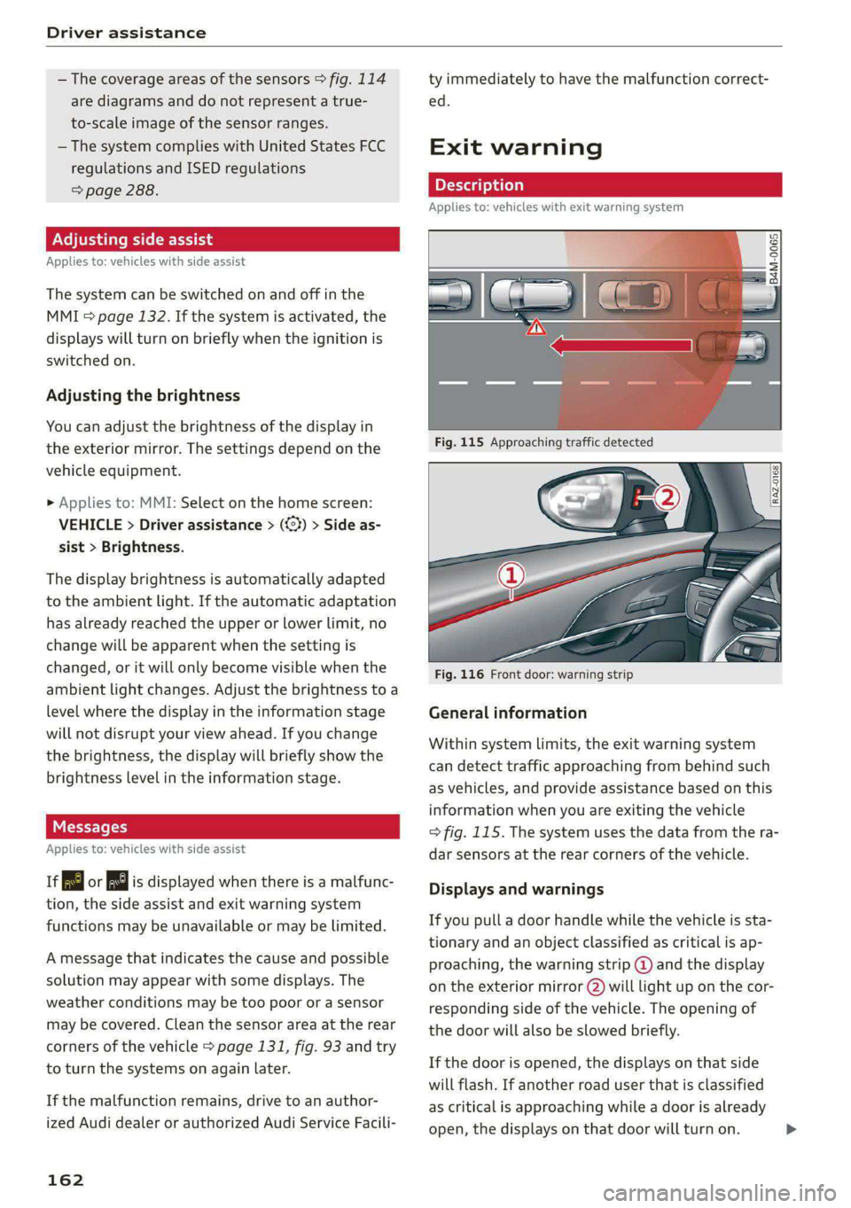
Exit warning
Applies to: vehicles with exit warning system
Fig. 116 Front door: warning strip
General information
Within system limits, the exit warning system
can detect traffic approaching from behind such
as vehicles, and provide assistance based on this
information when you are exiting the vehicle
> fig. 115. The system uses the data from the ra-
dar sensors at the rear corners of the vehicle.
Displays and warnings
If you pull a door handle while the vehicle is sta-
tionary and an object classified as critical is ap-
proaching, the warning strip @ and the display
on the exterior mirror (2) will light up on the cor-
responding side of the vehicle. The opening of
the door will also be slowed briefly.
If the door is opened, the displays on that side
will flash. If another road user that is classified
as critical is approaching while a door is already
open, the displays on that door will turn on.
Page 179 of 308
4KE012721BF
Telephone
Disconnecting a mobile device
Applies to: vehicles with telephone
> To disconnect a Bluetooth device from the MMI,
use the Connected devices menu > page 230.
Using the Audi phone
box
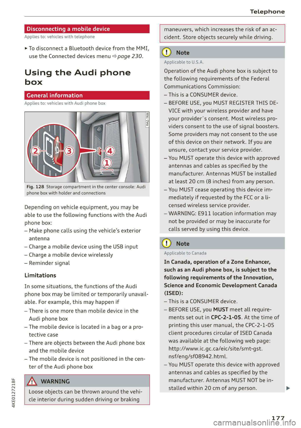
General information
Applies to: vehicles with Audi phone box
3
3 g ie
Fig. 128 Storage compartment in the center console: Audi
phone box with holder and connections
Depending on vehicle equipment, you may be
able to use the following functions with the Audi
phone box:
— Make phone calls using the vehicle’s exterior
antenna
— Charge a mobile device using the USB input
— Charge a mobile device wirelessly
— Reminder signal
Limitations
In some situations, the functions of the Audi
phone box may be limited or temporarily unavail-
able. For example, this may happen if
— There is one more than mobile device in the
Audi phone box
— The mobile device is located in a bag or a pro-
tective case
— There are objects between the Audi phone box
and the mobile device
— The mobile device is not positioned in the cen-
ter of the Audi phone box
maneuvers, which increases the risk of an ac-
cident. Store objects securely while driving.
ZA\ WARNING
Loose objects can be thrown around the vehi-
cle interior during sudden driving or braking
CG) Note
Applicable to U.S.A.
Operation of the Audi phone box is subject to
the following requirements of the Federal
Communications Commission:
— This is a CONSUMER device.
— BEFORE USE, you MUST REGISTER THIS DE-
VICE with your wireless provider and have
your provider’s consent. Most wireless pro-
viders consent to the use of signal boosters.
Some providers may not consent to the use
of this device on their network. If you are
unsure, contact your service provider.
— You MUST operate this device with approved
antennas and cables as specified by the
manufacturer. Antennas MUST be installed
at least 20 cm (8 inches) from any person.
— You MUST cease operating this device im-
mediately if requested by the FCC or a li-
censed wireless service provider.
— WARNING: E911 location information may
not be provided or may be inaccurate for
calls served by using this device.
@) Note
Applicable to Canada
In Canada, operation of a Zone Enhancer,
such as an Audi phone box, is subject to the
following requirements of the Innovation,
Science and Economic Development Canada
(ISED):
— This is a CONSUMER device.
— BEFORE USE, you MUST meet all require-
ments set out in CPC-2-1-05. At the time of
printing this user manual, the CPC-2-1-05
client procedures circular of ISED Canada
was available at the following web page:
http://www.ic.gc.ca/eic/site/smt-gst.
nsf/eng/sf08942.html.
— You MUST operate this device with approved
antennas
and cables as specified by the
manufacturer. Antennas MUST NOT be in-
stalled within 20 cm of any person.
177
Page 183 of 308
4KE012721BF
Telephone
— The contacts in the local MMI memory are
always visible and can be accessed by other
users.
— After switching off the ignition and exiting
the vehicle, the mobile device directory will
be loaded when the MMI is started again if
the mobile device is within range and the
Bluetooth function is switched on in the mo-
bile device and the MMI.
— Only the contacts in the local MMI memory
can be deleted.
Opening business cards
Applies to: vehicles with telephone
The business card shows you details about a con-
tact.
> To open a business card, press on a contact in
the directory, or
> Press © in the call list ©) > page 179, fig. 130.
Possible options in the business card:
> Call: press on a phone number.
> Storing a favorite: press W.
> Deleting a favorite: press W.
> Sending a text message: press {1.
>» Starting navigation: press on an address.
> Sending an e-mail: press on an e-mail address.
> Send contact: you can select Text message or
E-mail > page 183.
» Save as a shortcut > page 21, Shortcuts.
Listening to voicemail
Applies to: vehicles with telephone
> Applies to: MMI: Select on the home screen:
PHONE > Voicemail.
Requirement: there must be no voicemail num-
ber stored.
> Entering the voicemail number: enter the de-
sired number. Press OK.
Requirement: a voicemail number must be stor-
ed.
> Dialing the voicemail number: press Voice-
mail. The call begins immediately.
@) Tips
This service must be set up and activated by
the mobile phone service provider.
Dialing a telephone number
Applies to: vehicles with telephone
Depending on the vehicle equipment, you may
have the following options for dialing a phone
number:
— Using text input in the MMI > page 22.
— Using voice operation > page 25.
Call options
Applies to: vehicles with telephone
> To accept or end a call, press the @ button on
the multifunction steering wheel. Operating
=> page 12 and > page 28.
Depending on your mobile device, the following
options may be available in the MMI when there
is an incoming call:
— Answer
— Decline
— Message
If you exit the vehicle during a phone call, the
Bluetooth connection will be disconnected. De-
pending on your mobile device, phone calls in
progress may be automatically transferred from
the MMI to your mobile device.
G) Tips
The radio or media playback is muted during a
phone call.
PTT Tae RW urea]
Applies to: vehicles with telephone
Depending on your mobile device and the type of
connection, the following options may be availa-
ble during a call:
— End call
— Mute
181
Page 185 of 308
4KE012721BF
Telephone
— Decline with text message
— Edit voicemail number
Switching between two mobile devices
Requirement: phone 1 and phone 2 must be con-
nected to the MMI.
Switch telephones: the device name of the avail-
able mobile device is displayed. You can switch
the phone by pressing the button.
Ringtone and volume settings
— Ringtone and message volume: you can adjust
the volume using the slider.
— Ringtone: select a ringtone from the list.
— Microphone input level: you can adjust the in-
put Level of the microphone using the slider.
Data module serial number (IMEI)
Applies to: vehicles with data module
The serial number (IMEI) will be displayed.
Contact settings
Applies
to: vehicles with telephone
> Applies to: MMI: Select on the home screen:
PHONE > Contacts > ©.
Switching between two mobile devices
Requirement: telephone 1 and telephone 2 must
be connected.
Switch telephones: the device name of the avail-
able mobile device is displayed. You can switch
the phone by pressing the button.
The directory for the selected phone will be dis-
played.
Hide grayed-out contacts
When this function is switched on, contacts that
have no phone numbers stored for them will be
hidden.
Sort order
You can sort the contacts by Last name or First
name.
Download contacts
Requirement: a mobile device must be connected
to the MMI.
To update the contacts in the MMI, you can man-
ually download your mobile device contacts. De-
pending on the mobile device, you may need to
disconnect and reconnect the Bluetooth connec-
tion to update the contacts.
Importing contacts
Requirement: a USB storage device must be con-
nected to the Audi music interface > page 217.
The USB storage device contains contacts in the
vCard format (.vcf). They must not be located in
sub-folders.
Applies to MMI: Select: Import contacts > Search
for import data > USB device 1/USB device 2 >
desired contacts or Select all contacts > Start
import.
(i) Tips
—The imported contacts are stored in the lo-
cal MMI memory.
— There should be no other files or folders on
the storage medium containing the contacts
to be imported.
— Apple devices and MTP devices (such as
smartphones) are not recognized as USB
storage devices.
Messages
Text messages
Applies to: vehicles with telephone
Requirement: your mobile device must be con-
nected to the MMI via Bluetooth Message Access
Profile (Bluetooth MAP).
> Applies to: MMI: Select on the home screen:
MESSAGES > (©) > e-mail (phone 1)/e-mail
(phone 2)*.
The following functions are available:
— New text message*
— Inbox
— Sent
— Outbox*
— Drafts*
— Deleted
User defined*
183