charging system control unit AUDI E-TRON 2021 Owners Manual
[x] Cancel search | Manufacturer: AUDI, Model Year: 2021, Model line: E-TRON, Model: AUDI E-TRON 2021Pages: 308, PDF Size: 83.91 MB
Page 112 of 308
High-voltage system
Charging at household and industrial sockets
or at public charging stations with
alternating current (AC)
The vehicle's high-voltage battery can be charged
with alternating current (AC) via the charging
port () on the driver's side. Depending on the ve-
hicle equipment, there may be a second charging
port © on the front passenger's side. Both
charging ports have the same charging power.
You can use whichever charging port is more con-
venient for your charging setup. When using one
charging port, the opposite charging port is
locked.
Quick charging at public direct current (DC)
charging stations
The vehicle’s high-voltage battery can be charged
at a direct current (DC) charging station via the
charging port on the driver's side (S). There is a
significant decrease in charging time. The charg-
ing cable used may be a maximum of 98 feet (30
m).
Charging time
The duration of the charging process may vary
based on the following factors:
— Sockets being used (household or industrial
sockets)
— Country-specific system voltage, current
strength and number of available phases
— Household connection
— The value set for the charging power level on
the Audi charging system control unit
— Fluctuations in the system voltage
— The temperature outside the vehicle
— The temperature of the high-voltage battery
and the Audi charging system control unit.
— Settings for the climate control inside the vehi-
cle
— Current capacity of the charging connector
— Whether the ignition is on or off
Important safety precautions
ing the battery incorrectly (for example by
disregarding general safety precautions, using
unsuitable or damaged sockets and charging
cables, or charging with unsuitable electrical
equipment) and can lead to serious and fatal
injuries.
— Do not charge using sockets/electrical
equipment that is clearly damaged or instal-
led incorrectly.
— Never use charging equipment that is clearly
damaged and/or dirty. Check the charging
equipment for damage before every use.
— Never modify or repair any electrical compo-
nents, especially the high-voltage system.
— Never charge in areas at risk for explosions.
The components in the charging equipment
can trigger sparks, which can cause flamma-
ble or explosive fumes to ignite. To reduce
the risk of explosions, especially in garages,
make sure the Audi e-tron charging system
control unit is at least 19 inches (50 cm)
above the floor when charging.
— Never use the charging equipment with an
extension cord, a cable reel, a power strip,
or an adapter, for example, a travel adapter
or timer.
— Do not touch the contacts on the vehicle
charging port or charging equipment.
— Do not insert any objects in the vehicle
charging port or in the charging equipment.
— Always protect the sockets and connections
from water, moisture and other fluids.
— Never charge with both vehicle charging
ports at the same time.
— Only use the charging equipment provided
by the factory or the charging station cable.
ZA\ WARNING
Short circuiting, electric shock, explosions,
fire, and severe burns can result from charg-
ZA\ WARNING
Applies to: Audi charging systems
Sockets that are installed incorrectly can
cause electric shock or fire when charging the
high-voltage battery using the vehicle charg-
ing connection.
— Read all information and safety precautions
for Audi charging systems before using
them.
110
Page 113 of 308
4KE012721BF
High-voltage system
— Monitor the Audi charging system if it is be-
ing used near children.
— Installation and setup of the household con-
nection for Audi charging systems may only
be performed by a qualified electrician. The
qualified electrician is thereby responsible
for adhering to applicable standards and
regulations.
— Make sure that the household socket is
grounded and shielded from water.
— If Audi charging systems do not function ac-
cording to the specifications in the operat-
ing manual, they must not be used. Contact
an authorized Audi dealer or authorized
Audi Service Facility.
— Audi charging systems are intended for use
in private and semi-private areas (for exam-
ple, private property and company parking
lots). Depending on the country where the
vehicle is operated, charging with a mode 2
charging cable (meaning charging with the
Audi charging system) may be prohibited in
public areas. Contact an authorized Audi
dealer or authorized Audi Service Facility for
more information.
— Operate the Audi charging systems in power
networks that are properly grounded. It can-
not be used with non-grounded power net-
works (such as IT networks).
— When charging the high-voltage battery us-
ing household/industrial sockets, the elec-
trical installation can be used at full capaci-
ty. Audi recommends having a qualified elec-
trician regularly inspect the electrical instal-
lations that are used for charging.
— If possible, disconnect Audi charging sys-
tems from the power network during a
thunderstorm.
— Never submerge the Audi charging systems
or the connectors in water.
— Audi charging systems must only be cleaned
when the control unit is completely discon-
nected from the power supply and from the
vehicle. Use a dry towel to clean.
— Audi charging systems are only intended for
use on Audi vehicles and vehicles within the
Volkswagen Group. Using the devices on
vehicles made by another manufacturer is
not authorized.
() Note
— If the vehicle is not being used for long peri-
ods of time, the high-voltage battery must
be charged after four months at the latest
or the vehicle must be continuously con-
nected to a power source (for 50% charging
target > page 115). Otherwise, the high-
voltage battery could become damaged.
— Make sure that you always use the correct
charging equipment for the country in
which it is being used. Contact an author-
ized Audi dealer or authorized Audi Service
Facility for more information.
— On vehicles with only one charging port,
there is a cover on the opposite side of the
vehicle with no charging components instal-
led underneath it. Do not try to open this
cover.
G@) Tips
— Your vehicle can only be charged at charging
stations that meet the requirements in the
respective country and meet the following
standards, at a minimum:
— GB/T 18487.1 and GB/T 20234 (China)
— IEC 61851 and IEC 62196 (Europe)
— SAE J1772 (North America, Japan)
— You can use your Audi charging system if
there is a household or industrial connec-
tion available at the charging station.
(i) Tips
Applies to: Audi charging systems
— For an uninterrupted charging process, Audi
recommends only charging using sockets
that are connected to a separately protected
circuit.
— Audi recommends using Audi charging sys-
tems in the wall mount clip* during opera-
tion. If this is not possible, always position
Audi charging systems on a secure surface
during the charging process > A.
—To reduce the risk of overheating during op-
eration, do not place Audi charging systems
111
>
Page 114 of 308

High-voltage system
in direct sunlight for long periods of time. If
the control unit is overheated, the charging
process is automatically paused until the
temperature has lowered back within the
normal range.
Fig. 83 Left front side of the vehicle: opening the high-
voltage charging port door
Fig. 84 Charging unit: charging port and LED
Connecting the charging cable
If you charge your vehicle at a charging station,
the following sequence of steps may vary. Follow
the manufacturer guidelines and operating in-
structions for the charging station.
Requirement: the “P” gear must be selected, the
parking brake must be set, and drive ready mode
must have ended.
—If necessary, remove the charging cable from
the vehicle > page 119, Transport.
— Remove the cap from the charging cable if nec-
essary.
— First connect the charging cable to the power
supply, or remove it from the charging station.
— Unwind the charging cable completely.
— Unlock the charging port door by unlocking the
vehicle. In vehicles with a convenience key*, the
112
charging port door will be automatically un-
locked when the convenience key is near the
charger.
— Press the center of the button @ to open the
charging port door on the driver's side or front
passenger's side*.
— If you would like to use quick charging at public
direct current (DC) charging stations, open the
charging port cover (4).
— Plug the charging connector into the vehicle
charging port.
— Check if the charging option shown @) (immedi-
ate charging/timer charging) is the one you
would like to use for charging.
Starting to charge automatically (immediate
charging)
If charging is not delayed with a timer, the charg-
ing process will begin immediately. If necessary,
the charging station may need to be activated.
Follow the manufacturer guidelines and operat-
ing instructions for the charging station.
You can also adjust the charging process to your
preferences > page 115, Setting the charging
target, > page 116, Setting the timer,
= page 116, Advanced charging settings.
Timer charging
With timer charging, the charging process starts
and ends based on a timer that is set beforehand.
—To charge by timer, switch on the timer and
timer charging before exiting the vehicle
=> page 116.
If the charging connector is disconnected and re-
connected while timer charging is switched on,
immediate charging will activate automatically.
To continue charging by timer, timer charging
must be switched on again.
While charging
The charging display on the charging unit @) will
pulse green while charging. It will pulse is in
the instrument cluster. A label on the charging
unit @) informs you about the various displays
=> page 114.
The charging connector is locked while charging
and cannot be removed.
Page 121 of 308
4KE012721BF
High-voltage system
Always store the charging equipment securely
before transporting.
> Open the hood > page 234.
> Open the front storage compartment
=>page 79.
> Stow the charging equipment in the front stor-
age compartment.
> Close the front storage compartment and the
hood.
Audi e-tron compact charging system
Applies to: vehicles with Audi e-tron compact charging system
ZA\ WARNING
If the charging equipment is not secured or
positioned correctly, it can slide out of place
and endanger vehicle occupants when brak-
ing, when changing directions, or in a colli-
sion.
— Only transport the charging equipment in
the front storage compartment and never
unsecured or in the passenger compart-
ment.
() Note
Always lift or carry the Audi charging system
as one unit and never by the cables.
RAZ-0604
o 9 3)
—{4)
[RAZ-0726]
Fig. 86 Audi e-tron compact charging system: components
(example)
Observe the safety precautions > page 110, Im-
portant safety precautions.
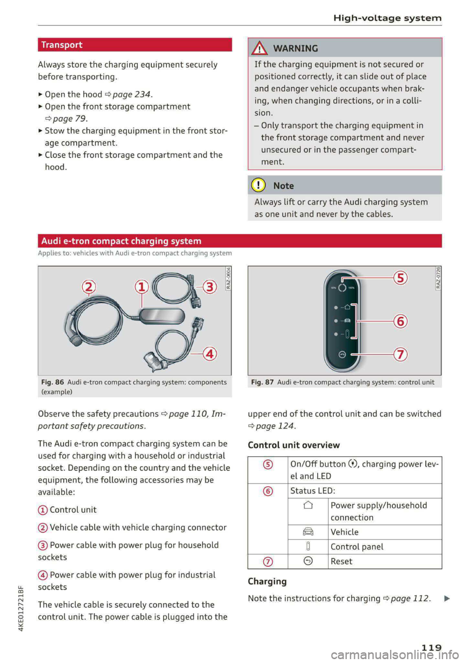
The Audi e-tron compact charging system can be
used for charging with a household or industrial
socket. Depending on the country and the vehicle
equipment, the following accessories may be
available:
@ Control unit
@ Vehicle cable with vehicle charging connector
@) Power cable with power plug for household
sockets
@ Power cable with power plug for industrial
sockets
The vehicle cable is securely connected to the
control unit. The power cable is plugged into the
Fig. 87 Audi e-tron compact charging system: control unit
upper end of the control unit and can be switched
=> page 124.
Control unit overview
© __ |On/Off button ®, charging power lev-
el and LED
© __ | Status LED:
a Power supply/household
connection
|Vehicle
0 Control panel
@ © |Reset
Charging
Note the instructions for charging > page 112.
119
>
Page 122 of 308

High-voltage system
Requirement: the correct power plug must be in-
stalled > page 124.
— Insert the plug into the socket.
— Plug the vehicle charging connector into the ve-
hicle charging port.
— The charging process e will start automatically.
— Once the charging process has completed, un-
lock the vehicle and remove the vehicle charg-
ing connector from the vehicle charging port.
Adjusting the charging power level
The control unit automatically recognizes the
voltage and the available current strength. You
can set whether you would like to charge with full
or reduced charging power. The last setting that
was selected will be saved and used again the
next time the vehicle is charged. If multiple
items are connected to the power circuit, the
charging current may be reduced when charging
Control unit: status and malfunction indicators
at a power outlet. This can help to prevent the
electrical equipment from overheating.
The vehicle has a minimum battery charging ca-
pacity of 880 W. Therefore, if the network volt-
age is less than 200 V, charging using a house-
hold socket will only be possible if the charging
power level is set to 100%. Otherwise, the charg-
ing process will not start.
Before charging, always check if the charging
power setting that was selected last is still suita-
ble.
— To set the charging power level, press and hold
the ® button © ® fig. 87 for at least two sec-
onds.
After the charging power level is set, the status
LEDs Q, {and (will flash green one time. The
selected value (50% or 100%) is displayed on the
left or right side of the ® button.
Indicator lights Meaning Solution
O Green The charger is ready to charge, | Starting the charging process
O O Off but is not charging. => page 112.
O & off
O 0 off
9 Off
O Flashing green _| The vehicle is being charged
QO Off with the ground conductor
E off monitor activated.
0 Off
Off
Flashing green
®O®OVSSC|I®OO0O
ance will be reduced.
C Yellow ed. Possible cause of the mal-
a
& oft is being used in single-phase
mode. The charging perform-
Off
The power cable has overheat- | After the cable cools down, the malfunc-
tion will be automatically cleared. Until it
Off function: a multi-phase socket | cools down, charging performance will be
reduced. If the malfunction continues,
have the power supply/household con-
nection checked by a qualified electrician.
120
Page 123 of 308
4KE012721BF
High-voltage system
Indicator lights Meaning Solution
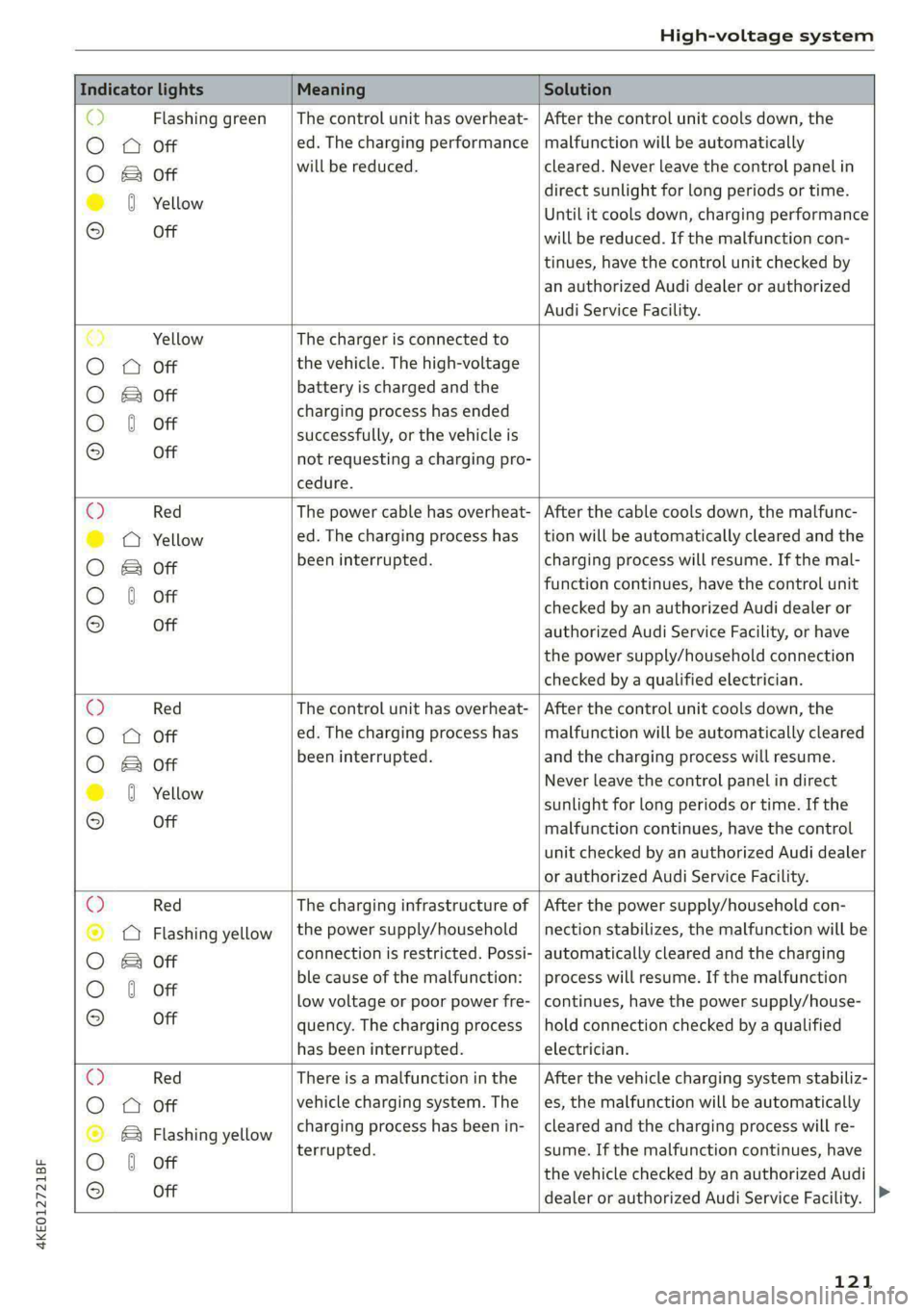
o> Flashing green |The control unit has overheat- | After the control unit cools down, the
O A Off ed. The charging performance | malfunction will be automatically
O B&B oft will be reduced. cleared. Never leave the control panel in
direct sunlight for long periods or time.
© 0 Yellow Until it cools down, charging performance
° Off will be reduced. If the malfunction con-
tinues, have the control unit checked by
an authorized Audi dealer or authorized
Audi Service Facility.
€) Yellow The charger is connected to
O QA Off the vehicle. The high-voltage
O B oft battery is charged and the
charging process has ended
O 0 off successfully, or the vehicle is
® Off not requesting a charging pro-
cedure.
© Red The power cable has overheat- | After the cable cools down, the malfunc-
© @ Yellow ed. The charging process has __| tion will be automatically cleared and the
O B oft been interrupted. charging process will resume. If the mal-
function continues, have the control unit
O 0 off checked by an authorized Audi dealer or
© Off authorized Audi Service Facility, or have
the power supply/household connection
checked by a qualified electrician.
Q Red The control unit has overheat- | After the control unit cools down, the
O
A Off ed. The charging process has_ | malfunction will be automatically cleared
O B oft been interrupted. and the charging process will resume.
© 8 Yeltow Never leave the control panel in direct
sunlight for long periods or time. If the
© Off malfunction continues, have the control
unit checked by an authorized Audi dealer
or authorized Audi Service Facility.
O Red The charging infrastructure of | After the power supply/household con-
© Q Flashing yellow |the power supply/household | nection stabilizes, the malfunction will be
O 2 oft connection is restricted. Possi- | automatically cleared and the charging
O 6 off ble cause of the malfunction: | process will resume. If the malfunction
low voltage or poor power fre- | continues, have the power supply/house-
© Off quency. The charging process | hold connection checked by a qualified
has been interrupted. electrician.
O Red There is a malfunction inthe | After the vehicle charging system stabiliz-
O QO Off vehicle charging system. The | es, the malfunction will be automatically
© B Flashing yellow charging process has been in- | cleared and the charging process will re-
O 6 of terrupted. sume. If the malfunction continues, have
© oH the vehicle checked by an authorized Audi
dealer or authorized Audi Service Facility.
121
Page 124 of 308
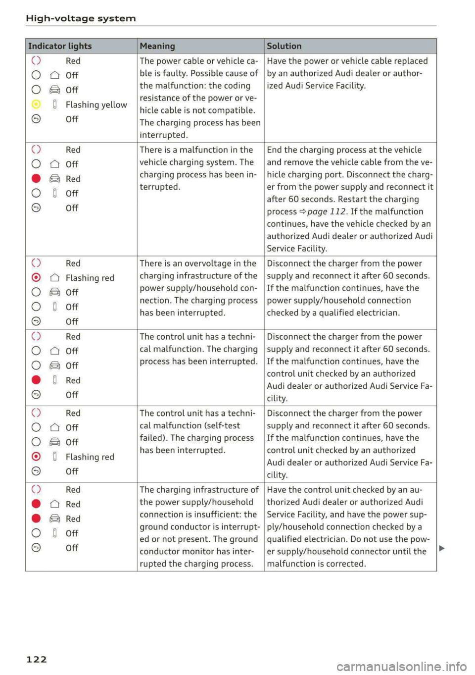
High-voltage system
Indicator lights Meaning Solution
@ Red The power cable or vehicle ca- | Have the power or vehicle cable replaced
O A Off ble is faulty. Possible cause of | by an authorized Audi dealer or author-
the malfunction: the coding ized Audi Service Facility.
O & Off
. resistance of the power or ve-
© 0 Flashing yellow hicle cable is not compatible.
© Off The charging process has been
interrupted.
@ Red There is a malfunction inthe | End the charging process at the vehicle
O QO Off vehicle charging system. The | and remove the vehicle cable from the ve-
@ Ered charging process has been in- |hicle charging port. Disconnect the charg-
O 6 of terrupted. er from the power supply and reconnect it
after 60 seconds. Restart the charging
9 Off process > page 112. If the malfunction
continues, have the vehicle checked by an
authorized Audi dealer or authorized Audi
Service Facility.
O Red There is an overvoltage inthe | Disconnect the charger from the power
© OQ Flashing red charging infrastructure of the |supply and reconnect it after 60 seconds.
O B oft power supply/household con- |If the malfunction continues, have the
O 6 oft nection. The charging process | power supply/household connection
© has been interrupted. checked by a qualified electrician.
Off
O Red The control unit has atechni- | Disconnect the charger from the power
O O Off cal malfunction. The charging | supply and reconnect it after 60 seconds.
O B oft process has been interrupted. |If the malfunction continues, have the
@ 6 Red control unit checked by an authorized
© Audi dealer or authorized Audi Service Fa-
© Off cility.
O Red The control unit has atechni- | Disconnect the charger from the power
O O Off cal malfunction (self-test supply and reconnect it after 60 seconds.
O B oft failed). The charging process | If the malfunction continues, have the
© 0 Flashi d has been interrupted. control unit checked by an authorized
ashing re Audi dealer or authorized Audi Service Fa-
OQ Off cility.
O Red The charging infrastructure of | Have the control unit checked by an au-
@ Red the power supply/household | thorized Audi dealer or authorized Audi
connection is insufficient: the | Service Facility, and have the power sup-
@ & Red
O 6 off ground conductor is interrupt- | ply/household connection checked by a
ed or not present. The ground | qualified electrician. Do not use the pow-
© Off conductor monitor has inter-
rupted the charging process.
er supply/household connector until the
malfunction is corrected.
122
Page 125 of 308
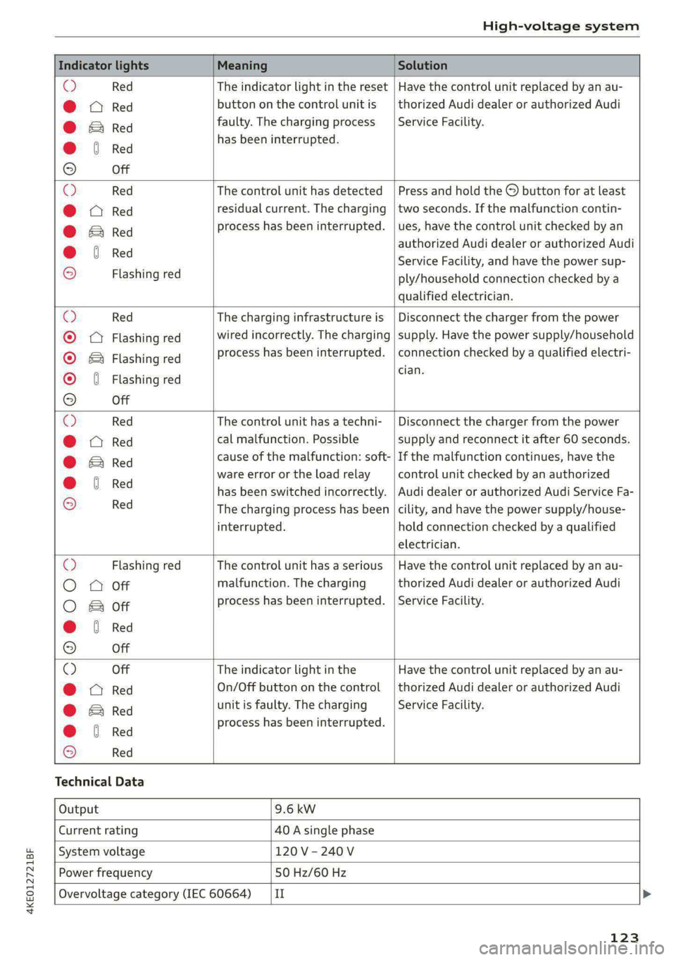
4KE012721BF
High-voltage system
Indicator lights Meaning Solution
© Red The indicator light in the reset | Have the control unit replaced by an au-
@ CQ Red button on the control unit is | thorized Audi dealer or authorized Audi
@ BRe faulty. The charging process | Service Facility.
@ 6 Red has been interrupted.
9 Off
O Red The control unit has detected | Press and hold the © button for at least
@ X Red residual current. The charging | two seconds. If the malfunction contin-
@ Si Red process has been interrupted. | ues, have the control unit checked by an
@ 6 Red authorized Audi dealer or authorized Audi
© . Service Facility, and have the power sup-
2 Flashing red ply/household connection checked by a
qualified electrician.
O Red The charging infrastructure is | Disconnect the charger from the power
® QQ Flashing red wired incorrectly. The charging | supply. Have the power supply/household
© & Flashing red process has been interrupted. | connection checked by a qualified electri-
cian.
© { Flashing red
9 Off
O Red The control unit has atechni- | Disconnect the charger from the power
@ CO Red cal malfunction. Possible supply and reconnect it after 60 seconds.
@ Bred cause of the malfunction: soft- | If the malfunction continues, have the
@ 6 Red ware error or the load relay control unit checked by an authorized
© has been switched incorrectly. | Audi dealer or authorized Audi Service Fa-
2 Red The charging process has been |cility, and have the power supply/house-
interrupted. hold connection checked by a qualified
electrician.
O Flashing red The control unit has a serious | Have the control unit replaced by an au-
O QO Off malfunction. The charging thorized Audi dealer or authorized Audi
O 2 oft process has been interrupted. | Service Facility.
@ & Red
9 Off
© Off The indicator light in the Have the control unit replaced by an au-
@ A Red On/Off button on the control | thorized Audi dealer or authorized Audi
@ E&rRed unit is faulty. The charging Service Facility.
@ 6 Red process has been interrupted.
© Red
Technical Data
Output 9.6 kw
Current rating 40 A single phase
System voltage 120V-240V
Power frequency 50 Hz/60 Hz
Overvoltage category (IEC 60664) {II
123
Page 126 of 308
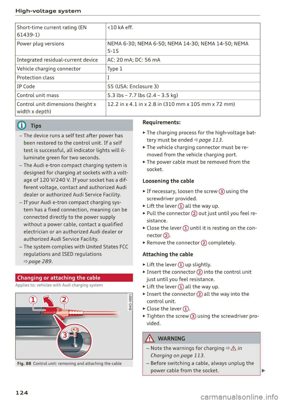
High-voltage system
Short-time current rating (EN <10 kA eff.
61439-1)
Power plug versions NEMA 6-30; NEMA 6-50; NEMA 14-30; NEMA 14-50; NEMA
5-15
Integrated residual-current device AC: 20 mA; DC: 56 mA
Vehicle charging connector Type l
Protection class I
IP Code 55 (USA: Enclosure 3)
Control unit mass 5.3 lbs - 7.7 lbs (2.4 - 3.5 kg)
Control unit dimensions (height x
width x depth)
12.2 in x 4.1 in x 2.8 in (310 mm x 105 mm x 72 mm)
@) Tips
— The device runs a self test after power has
been restored to the control unit. If a self
test is successful, all indicator lights will il-
luminate green for two seconds.
— The Audi e-tron compact charging system is
designed for charging at sockets with a volt-
age of 120 V/240 V. If your socket has a dif-
ferent voltage, contact and authorized Audi
dealer or authorized Audi Service Facility.
— If your Audi e-tron compact charging sys-
tem has a fixed connection, meaning can be
connected directly to the power supply
without a power cable, contact a qualified
electrician or an authorized Audi dealer or
authorized Audi Service Facility.
— The system complies with United States FCC
regulations and ISED regulations
=> page 289.
Changing or attaching the cable
Applies to: vehicles with Audi charging system
i?
B4G-0681
Fig. 88 Control unit: removing and attaching the cable
124
Requirements:
> The charging process for the high-voltage bat-
tery must be ended > page 113.
> The vehicle charging connector must be re-
moved from the vehicle charging port.
> The power cable must be removed from the
socket.
Loosening the cable
» If necessary, loosen the screw @) using the
screwdriver provided.
> Lift the lever @ all the way up.
> Pull the connector @) out just until you feel re-
sistance.
> Close the lever @ until it is resting on the con-
nector @).
> Remove the connector (2) completely.
Attaching the cable
> Lift the lever @ up slightly.
> Insert the connector (2) into the control unit
just until you feel resistance.
> Lift the lever @ all the way up.
» Insert the connector (2) all the way into the
control unit.
> Close the lever (@).
> Tighten the screw @) using the screwdriver pro-
vided.
ZA WARNING
— Note the warnings for charging > A in
Charging on page 113.
— Before switching a cable, always unplug the
power cable from the socket. >
Page 127 of 308
4KE012721BF
High-voltage system
— Only change cables in a dry environment.
— The Audi charging system may only be used
as a complete unit consisting of the power
cables, the control unit, and the vehicle ca-
ble. Depending on the country, the total
length of the power cable, control panel and
vehicle cable may be restricted, for example
to 24.6 feet (7.5 m) in the USA. Audi recom-
mends using only cables approved by Audi.
@) Tips
The power cable with the power connector for
industrial sockets and the Audi charging sys-
tem control unit are designed to work togeth-
er. Changing the power cable to another con-
nector type may reduce the available charging
power of the entire system. Limitations on
the ability to transfer power (current capacity)
depending on the phase and the number of
available phases may affect the available
charging power.
Wall mo clip
Applies to: vehicles with wall mount clip
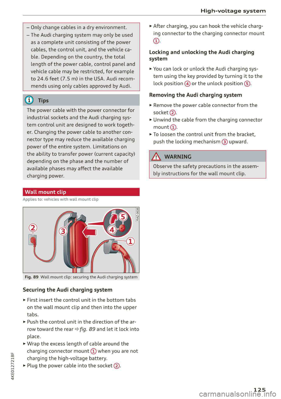
RAZ-0638,
Fig. 89 Wall mount clip: securing the Audi charging system
Securing the Audi charging system
> First insert the control unit in the bottom tabs
on the wall mount clip and then into the upper
tabs.
> Push the control unit in the direction of the ar-
row toward the rear > fig. 89 and let it lock into
place.
> Wrap the excess length of cable around the
charging connector mount @ when you are not
charging the high-voltage battery.
> Plug the power cable into the socket (2).
> After charging, you can hook the vehicle charg-
ing connector to the charging connector mount
©.
Locking and unlocking the Audi charging
system
> You can lock or unlock the Audi charging sys-
tem using the key provided by turning it to the
lock position @) or the unlock position 6).
Removing the Audi charging system
> Remove the power cable connector from the
socket (2).
> Unwind the cable from the charging connector
mount (@).
> To loosen the control unit from the bracket,
push the locking mechanism @) upward.
ZX WARNING
Observe the safety precautions in the assem-
bly instructions for the wall mount clip.
125