Switch layout AUDI Q2 2021 Owner´s Manual
[x] Cancel search | Manufacturer: AUDI, Model Year: 2021, Model line: Q2, Model: AUDI Q2 2021Pages: 364, PDF Size: 87.77 MB
Page 14 of 364

Instruments and controls
- Some of the items of equipment listed in
this section are only fitted on certain
mod
els or are optional extras.
- Applies to right-hand drive vehicles: The ar
rangement of switches and controls may be
slightly different from the layout shown on
tapage
10. However, the symbols used to
identify the controls are the same.
Instrument cluster
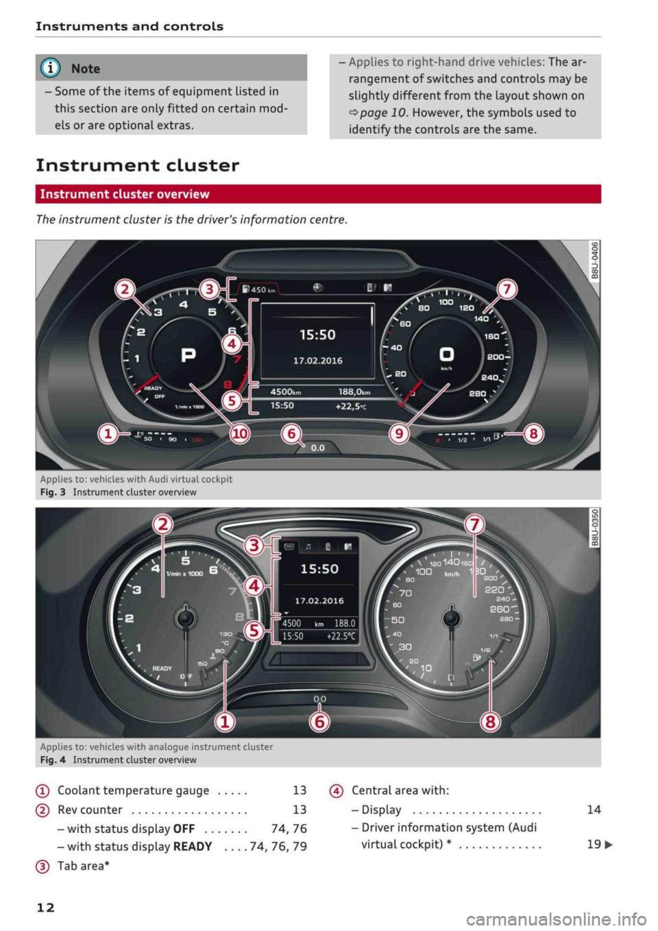
Instrument cluster overview
The
instrument cluster is the driver's information centre.
15:50
17.02.2016
188,0km
+22,5°c
Applies to:
vehicl.es
with Audi virtual cockpit
Fig.
3 Instrument cluster overview
„
\
IS0140180
/
,
100
kn,^
1
3DI '
BO
£00
22Q
4500 km 188.0
15:50
+22.5°C
Applies to: vehicles with analogue instrument cluster
Fig.
4 Instrument cluster overview
(T)
Coolant
temperature
gauge 13
(D Rev counter 13
-with status display OFF 74,76
- with status display READY 74, 76, 79
(D
Tab area*
(?) Central area
with:
- Display
- Driver information system (Audi
virtual cockpit) *
14
19
•
12
Page 225 of 364

Navigation
Adjust route*: Move your finger
over
the MMI
touch padVrotary pushbutton to adjust the route
on the overview map.
Map settings
Applies
to: vehicles with navigation system
•
Press the
|NAV/MAP|
button repeatedly until
the map is displayed.
•
Select: right control button > Map settings.
Depending on the function seLected, you can use
the following settings:
Map colours
day/night: The map is displayed with a
Light/dark
background colour.
automatic: The colour of the map changes to
match the current light conditions (e.g. from day
to night when driving through tunnels).
Map display
Standard: Refer to
opage
219, Fig. 182.
Google Earth*: Refer to
^>page
222, Fig. 183.
Traffic*1);
Refer to
^>page
225, Fig. 187.
Map orientation
destination: The map indicates the destination
and is set to face north.
2D driving position/2D north map: The map de
picts the vehicle's current position. The map is
set to face the direction of travel or north.
3D driving position*: The current vehicle
posi
tion is displayed in a three-dimensional map, and
the map is set to face the direction of
travel.
If
the map scale is more than 100 km, the map is
set to
face north.
overview: The entire route from the vehicle
posi
tion to the final destination or next stopover is
displayed on the map. The map scale varies ac
cording to the Length of the route and is adapted
automatically. The map is set to face north.
Route information
The display of route information such as the
street you are currently on, upcoming turn-offs,
traffic information or special destinations on the
current route can be switched on/off.
Automatic zoom
on:
The map scale is adjusted automatically ac
cording to the category of the road you are on
(motorway, major
road,
other road) to ensure
that
you always have the best possible overview
of the route ahead. When there is an upcoming
turn-off, the map display will also be automati
cally adjusted so that you have a more detailed
view.
intersection: When route guidance is active and
there are upcoming turn-offs, the map dispLay
will temporarily switch to a more detailed scale
so that the road layout can be identified more
easily.
off: The map scale you have set will remain
unal
tered.
Map content
The dispLay of map content such as weather in
formation,
traffic information or favourite desti
nations can be switched on and off.
The weather* is shown on the map if the scale is
set to 5 km or more
^>page
216, Fig. 179.
CO
rN
IV
rN
t-H
o <
x)
This function is not available in the Mexican market.
221
Page 337 of 364

Fuses and bulbs
: -•.
-
i:i
m
R2 R3
F22
F-XII
F31
F30
:-:-.'
'.,
FM F43
F49
F!)3
F52
F51
R!,
a
R6
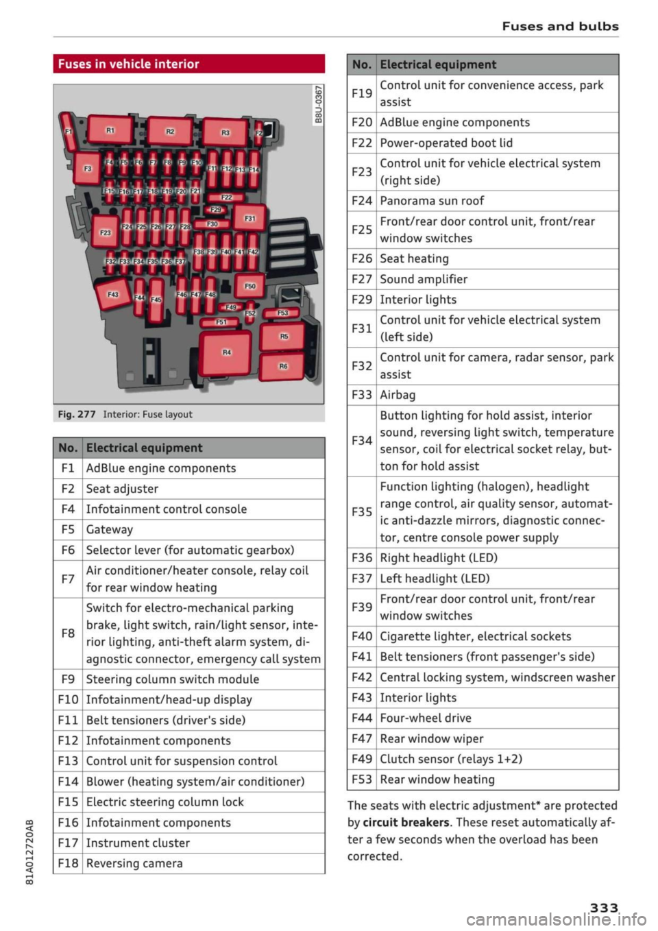
Fig.
277 Interior: Fuse layout
No.
Fl
F2
F4
F5
F6
F7
F8
F9
F10
Fll
F12
F13
F14
F15
F16
F17
F18
Electrical equipment
AdBlue engine components
Seat adjuster
Infotainment control console
Gateway
Selector lever (for automatic gearbox)
Air conditioner/heater console, relay coil
for rear window heating
Switch for electro-mechanical parking
brake,
light switch,
rain/Light
sensor, inte
rior lighting, anti-theft
aLarm
system, di
agnostic connector, emergency call system
Steering column switch module
Infotainment/head-up display
Belt tensioners (driver's side)
Infotainment components
Control unit for suspension control
Blower (heating system/air conditioner)
Electric steering column lock
Infotainment components
Instrument cluster
Reversing camera
No.
F19
F20
F22
F23
F24
F25
F26
F27
F29
F31
F32
F33
F34
F35
F36
F37
F39
F40
F41
F42
F43
F44
F47
F49
F53
Electrical equipment
Control unit for convenience access, park
assist
AdBlue engine components
Power-operated boot lid
Control unit for vehicle electrical system
(right side)
Panorama sun roof
Front/rear door control unit, front/rear
window switches
Seat heating
Sound amplifier
Interior lights
Control unit for vehicle electrical system
(left side)
Control unit for camera, radar sensor, park
assist
Airbag
Button Lighting for hold assist, interior
sound,
reversing light switch, temperature
sensor, coiL for electrical socket reLay, but
ton for hold assist
Function lighting (halogen), headlight
range control, air quality sensor, automat
ic anti-dazzle mirrors, diagnostic connec
tor, centre console power supply
Right headlight (LED)
Left headlight (LED)
Front/rear door control unit, front/rear
window switches
Cigarette lighter, electrical sockets
Belt tensioners (front passenger's side)
Central locking system, windscreen washer
Interior lights
Four-wheel drive
Rear window wiper
Clutch sensor (relays 1+2)
Rear window heating
The seats with electric adjustment* are protected
by circuit breakers. These reset automatically af
ter a few seconds when the overload has been
corrected.
333
Page 338 of 364

Fuses and bulbs
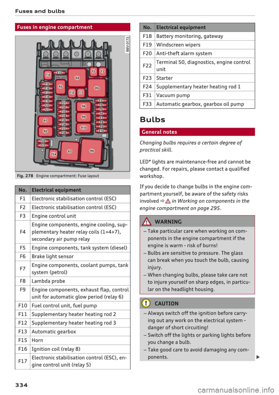
Fuses in engine compartment
Fig.
278 Engine compartment: Fuse layout
No.
Fl
F2
F3
F4
F5
F6
F7
F8
F9
F10
Fll
F12
F13
F15
F16
Electrical equipment
Electronic stabilisation control (ESC)
Electronic stabilisation control (ESC)
Engine control unit
Engine components, engine cooling, sup
plementary heater relay coils (1+4+7),
secondary air pump relay
Engine components, tank system (diesel)
Brake Light sensor
Engine components, coolant pumps, tank
system (petrol)
Lambda probe
Engine components, exhaust flap, control
unit for automatic glow period (relay 6)
Fuel control unit, fuel pump
Supplementary heater heating rod 2
Supplementary heater heating rod 3
Automatic gearbox
Horn
Ignition coil (relay
8)
Electronic stabilisation control (ESC), en
gine control unit (relay 5)
No.
F18
F19
F20
F22
F23
F24
F31
F33
Electrical equipment
Battery monitoring, gateway
Windscreen wipers
Anti-theft alarm system
Terminal 50, diagnostics, engine control
unit
Starter
Supplementary heater heating rod 1
Vacuum pump
Automatic gearbox, gearbox oil pump
Bulbs
General notes
Changing bulbs requires a certain degree of
practical
skill.
LED*
lights are maintenance-free and cannot be
changed.
For repairs, please contact a qualified
workshop.
If
you
decide to change bulbs in the engine com
partment yourself, be aware of the safety risks
involved
*
A in Working on components in the
engine compartment on page 295.
WARNING
- Take particular care when working on com
ponents in the engine compartment if the
engine is warm - risk of burns!
- Bulbs are sensitive to pressure. The glass
can break when you touch the bulb, causing
injury.
- When changing bulbs, please take care not
to injure yourself on sharp edges, in particu
lar on the headlight housing.
© CAUTION
-Always switch off the ignition before carry
ing out any work on the electrical system -
danger of short circuiting!
- Switch off the Lights or parking lights before
you change a bulb.
- Take good care to avoid damaging any com
ponents.
334