check engine AUDI Q3 2018 Owner's Manual
[x] Cancel search | Manufacturer: AUDI, Model Year: 2018, Model line: Q3, Model: AUDI Q3 2018Pages: 230, PDF Size: 57.03 MB
Page 167 of 230
0 co ......
"' ,....
"' ...... 0 0 :::,
00
@ Tips
- Only charge the vehicle battery through the
connections in the engine compartment.
- Read all of the manufacturer's instructions
for the charger before charging the vehicle
battery.
Windshield washer system
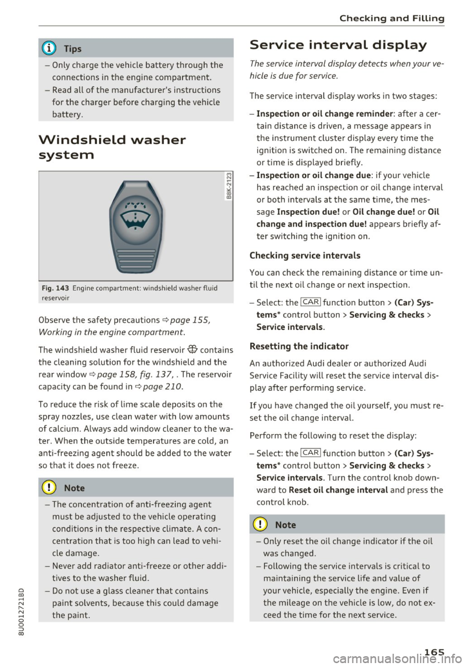
Fig. 143 Engine compartment: windshield washer fluid
reservoir
Observe the safety precautions q page 155,
Working in the engine compartment.
M N ~ N
"' a) ID
The windshield washer fluid reservoir W contains
the cleaning solution for the windshield and the rear w indow
q page 158, fig . 137,. The reservoir
capacity can be found in
qpage 210.
To reduce the risk of lime scale deposits on the
spray nozzles, use clean water with low amounts
of calc ium . Always add window cleaner to the wa
ter. When the outside temperatures a re cold, an
anti-freezing agent should be added to the water
so that it does not freeze.
- The concent ration of anti-freezing agent
must be adjusted to the vehicle operating
conditions in the respective climate. A con
cent ration that is too high can lead to vehi
cle damage.
- Never add radiator anti-freeze or other addi
tives to the washer fluid.
- Do not use a glass cleaner that contains
paint solvents, because this could damage
the paint .
Checking and Filling
Service interval display
The service interval display detects when your ve
hicle is due for service .
The service interval display works in two stages:
-Inspection or oil change reminder : after a cer-
tain distance is driven, a message appears in
t he instrument cluster display every time the
ignition is switched on. The remaining distance
or time is displayed br iefly.
- Inspection or oil change due: if your vehicle
has reached an inspection or oil change interval
or both intervals at the same time, the mes
sage
Inspection due! or Oil change due! or Oil
change and inspection due!
appears briefly af
ter sw itching the ignition on.
Checking service intervals
You can check the remaining distance or time un
ti l the next oi l change or next inspection .
- Select: the
I CARI function button > (Car) Sys
tems*
control button > Servicing & checks >
Service intervals .
Resetting the indicator
An autho rized Aud i dea ler or a uthorized Audi
Service Facility will reset the service in terva l dis
play after performing service .
If you have changed the o il yourself, you must re
set the oil change interval.
Perform the follow ing to reset the d isplay:
- Select: the
I CAR I function button > (Car) Sys
tems *
control button > Servicing & checks >
Service intervals . Turn the control knob down
ward to
Reset oil change interval and press the
control knob .
~ Note
-Only reset the oil change ind icator if the oil
was changed.
- Following the service intervals is crit ica l to
ma intaining the service life and value of
your vehicle, especially the engine . Even if
the mileage on the vehicle is low, do not ex
ceed the time for the next service.
165
Page 194 of 230

Emergency assistance
& WARNING
You or your passengers could be injured while changing a wheel if you do not follow these
safety precautions :
- If you have a flat ti re, move a safe d ista nee
off the road . Turn off the engine, turn the
emergency flashers on and use other warn·
ing devices to alert other motorists.
- Make sure that passengers wait in a safe
place away from the vehicle and well away
from the road and traffic.
- To help prevent the vehicle from moving
suddenly and possibly slipping off the jack,
always fully set the parking brake and block
the front and back of the wheel diagonally
opposite the wheel being changed with the
folding chocks or other objects. When one
front wheel is lifted off the ground, placing
the Automatic Transmission in "P" (Park)
will
not prevent the vehicle from moving.
- Before you change a wheel, be sure the
ground is level and firm. If necessary, use a
sturdy board under the jack .
- Always store the vehicle tool kit, the jack
and the replaced tire in the luggage com
partment
c:> page 102 .
(D Tips
Obey all laws.
Changing a wheel
When you change a wheel, follow the sequence
described below step-by-step and in exactly that
order.
1. Remove the decorative wheel cover* or the
wheel bolt caps*. For more details see also
<=:>page 193.
2. Loosen the wheel bolts c:> page 193.
3. Locate the proper mounting point for the
jack and align the jack below that point
<=:>page 194.
4. Lift the car with the jack c:> page 194 .
5. Remove the wheel with the flat tire and then
install the
spare tire <=:>page 195.
6. Tighten all wheel bolts lightly.
7.
Lower the vehicle with the jack.
192
8. Use the wheel bolt wrench and firmly tighten
all wheel bolts in a crisscross pattern
<=:>page 193.
9. Replace the decorative wheel cover* or the
wheel bolt caps*.
& WARNING
Always read and follow all WARNINGS and in
formation
c:> .&. in Raising the vehicle on
page 194
and <=:>page 196.
After changing a wheel
A wheel change is not complete without the do·
ing the following .
.,. Always store the vehicle tool kit, the jack* and
the replaced tire in the luggage compartment
c:>page 102.
.,. Check the tire pressure of the spare tire as soon
as possible .
.,. As soon as possible, have the
tightening tor·
ques
on all wheel bolts checked with a torque
wrench. The correct tightening torque is
10S ft lbs (140 Nm).
.,. Have the flat tire
replaced as soon as possible.
(D Tips
- If you notice that the wheel bolts are cor
roded and difficult to turn while changing a
tire, they should be replaced before you check the tightening torque.
- Drive at reduced speed until you have the
tightening torques checked .
Page 201 of 230
Fuses and bulbs
Electrical fuses
Changing fuses
A fuse that has blown will have metal strips that have burned through .
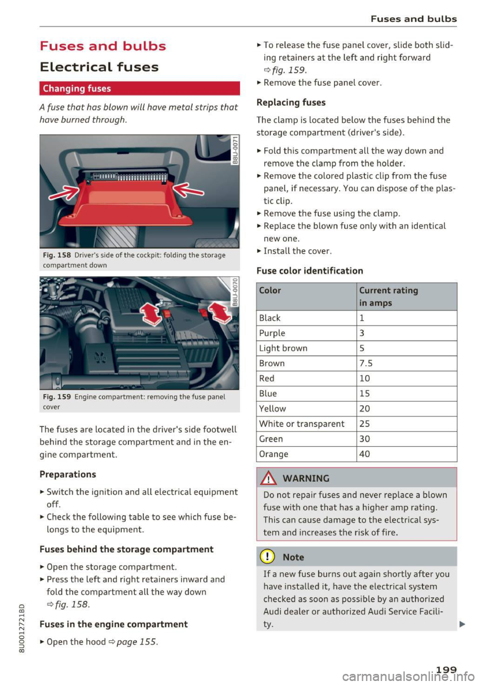
Fig. 158 Driver's side of the cockpit: fold ing the storage
co mpartme nt dow n
Fig. 159 Engine compartment: removing the fuse pane l
cover
The fuses are located in the driver's side footwell
behind the storage compartment and in the en
gine compartment .
Preparations
.. Switch the ign ition and all electr ical equipment
off .
.. Check the following table to see which fuse be-
longs to the equipment .
Fuses behind the storage compartment
.. Open the storage compartment .
.. Press the left and right retainers inward and
fold the compartment all the way down
a ¢fig. 158 . co ...... N ~ Fuses in the engine compartment
'"' 0 g .. Open the hood ¢ page 155.
co
Fuses and bulbs
.. To release the fuse panel cover, slide both slid
ing retainers at the left and right forward
¢ fig. 159 .
.. Remove the fuse panel cover .
Replacing fuses
The clamp is located below the fuses behind the
storage compartment (driver's side) .
.. Fold th is compartment all the way down and
remove the clamp from the holder .
.. Remove the colored plastic clip from the fuse
panel, if necessary . You can dispose of the plas
tic clip .
.. Remove the fuse using the clamp .
.. Replace the blown fuse only with an identical
new one .
.. Install the cover.
Fuse color identification
Color Current rating
in amps
Black 1
Purple 3
Light brown 5
Brown 7.5
Red 10
Blue 15
Yellow 20
White or transparent 25
Green 30
Orange 40
A WARNING
Do not repair fuses and never replace a blown
fuse with one that has a higher amp rat ing .
This can cause damage to the electr ical sys
tem and increases the risk of fire.
(D Note
If a new fuse burns out again shortly after you
have installed it, have the electrical system
checked as soon as poss ible by an authorized
Audi dealer or authorized Audi Service Facili
ty.
199
Page 205 of 230
0 co ......
"' ,....
"' ...... 0 0 :::,
00
Emergency situations
General
This chapter is intended for trained emergency
crews and working personnel who have the nec
essary tools and equipment to perform these
operations.
Starting by pushing or
towing
CD Note
Vehicles with an automatic transmission
cannot be started by pushing or towing.
Starting with jumper
cables
If necessary, the engine can be started by con
necting it to the battery of another vehicle.
If the engine should fail to start because of a dis
charged or weak battery, the battery can be con
nected to the battery of
another vehicle, using a
pair of jumper cables to start the engine.
Jumper cables
Use only jumper cables of sufficiently large cross
section
to carry the starter current safely. Refer
to the manufacturer's specifications.
Use only jumper cables with
insulated terminal
clamps which are distinctly marked:
plus(+) cable in most cases colored red
minus(·) cable
in most cases colored black.
A WARNING
Batteries contain electricity, acid, and gas.
Any of these can cause very serious or fatal in
jury. Follow the instructions below for safe
handling of your vehicle's battery.
-Always shield your eyes and avoid leaning
over the battery whenever possible.
-A dead battery can freeze at temperatures
around 32 °F (0 °C). If the vehicle battery is
frozen, you must thaw it before connecting
the jump start cables. If you do not, this in-
Emergency situations
creases the risk of an explosion and chemi
cal burns. After jump starting the vehicle,
drive to an authorized Audi dealer or author
ized Audi Service Facility immediately to
have the vehicle battery checked.
- Do not allow battery acid to contact eyes or
skin . Flush any contacted area with water
immediately.
- Improper use of a booster battery to start a
vehicle may cause an explosion .
- Vehicle batteries generate explosive gases.
Keep sparks, flame and lighted cigarettes
away from batteries.
- Do not try to jump start any vehicle with a
low acid level in the battery .
- The voltage of the booster battery must also
have a 12-Volt rating. The capacity (Ah) of
the booster battery should not be lower
than that of the discharged battery. Use of
batteries of different voltage or substantial
ly different "Ah" rating may cause an explo
sion and personal injury.
- Never charge a frozen battery. Gas trapped
in the ice may cause an explosion.
- Never charge or use a battery that has been
frozen . The battery case may have be weak
ened.
- Use of batteries of different voltage or sub
stantially different capacity (Ah) rating may
cause an explosion and injury. The capacity (Ah) of the booster battery should not be
lower than that of the discharged battery.
- Before you check anything in the engine
compartment, always read and heed all
WARNINGS
qpage 155.
CD Note
-Applying a higher voltage booster battery
will cause expensive damage to sensitive electronic components, such as control
units, relays, radio, etc.
- There must be no electrical contact between
the vehicles as otherwise current could al
ready start to flow as soon as the positive
(+) terminals are connected.
203
Page 207 of 230
-Do not bend over the batteries -danger of
chemical burns!
- The battery cell locking screws must be
tightened securely.
- Before you check anything in the engine
compartment, a lways read and heed all
WARNINGS
¢ page 155.
(D Note
Improper hook-up of jumper cables can ruin
the generator.
- Always connect POSITIVE(+) to POSITIVE
( + ), and NEGATIVE(-) to NEGATIVE(-)
ground post of the battery manager contro l
unit.
- Check that all screw p lugs on the battery
cells are screwed in firmly . If not, tighten
plugs prior to connecting clamp on negative
battery terminal.
- Please note that the procedure for connect
ing a jumper cable as described above ap
plies specif ically to the case of your vehicle
being jump started. When you are giv ing a
jump start to another vehicle, do
not con
nect the negative( -) cab le to the negative
(-) terminal on the discharged battery@
¢ fig. 161. Instead, securely connect the
negative (-) cable to either a solid metal
component that is firm ly bolted to the en
gine block or to the engine block itself. If
the battery that is being charged does not
vent to the outs ide, escaping battery gas
could ignite and explode!
Towing with a tow truck
General hints
Your Audi requires special handling for towing .
The following information is to be used by com
mercial tow tr uck operators who know how to op
erate their equipment safely .
-Never tow your Audi, towing will cause dam-
age to the engine and transmission .
a '.:: -Never wrap the safety chains or winch cables
~ around the brake lines. N
"" 0 0 ::, (X)
Emergency situations
-To prevent unnecessary damage , your Audi
must be transported with a flat bed truck.
- To load the vehicle on to the flat bed, use the
towing loop found in the vehicle tools and at·
tach to the front or rear anchorage
¢ page 205 and ¢ page 206.
A WARNING ~ -
A veh icle being towed is not safe for passen
gers . Never allow anyone to ride in a vehicle
being towed, for any reason.
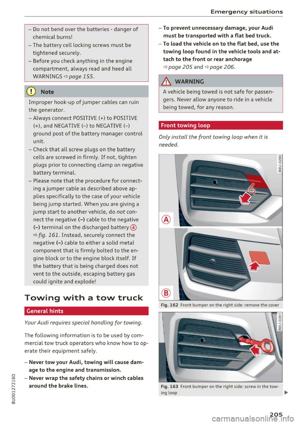
Front towing loop
Only install the front towing loop when it is
needed.
®
®
0 0:, N 9 ::> 0:, a)
Fig. 162 Front bumpe r on t he r ight s ide: remove t he cover
Fig. 163 Front bumpe r on t he right side: screw in the tow-
in g loop ...
205
Page 210 of 230
Emergency situations
distribut ion and ba lance . This might hap
pen, for example, when heavy compo
nents such as the engine block or trans
miss io n are removed.
- When removing heavy components like
th ese, a nch or vehicle to ho ist o r add corre
sponding weights to maintain the cen ter of
gr avity. Otherwise , th e vehicle migh t ti lt or
s lip off the hoist, causing s erious p erso nal
rnJury.
0 Note
- Be aware of t he following poi nts before lift
i ng t he veh icle:
-The vehicle should never be lifted or
jacked up from underneath the engine oil
pan , the transmission housing, the front
or rear axle or the body side members.
This could lead to serious damage.
- To avoid damage to the underbody or
chassis frame, a rubber pad must be in·
serted between the floor jack and the lift points.
- Before driving over a workshop hoist,
check that the vehicle weight does not
exceed the permissible lifting capacity of
the hoist .
- Before driving over a workshop hoist, en
sure that there is sufficient clearance be
tween the hoist and low parts of the ve ·
hide .
208
Page 211 of 230

a
co
.... N
" N .... 0 0 ::, co
Technical data
Vehicle specifications
XXXXX XX · X · XXXX XXX xx
CD-+ IAH RIG. • IOEN T • NII. VOE£ • WIT • Nil. XXXXXX XX XX X XX XXX XXX
IYP/TYP! XXX XXX
xx xxxxxxx xx xx xx
XXX KW XXX
®i 11)10Al<8./lil1R.k8. a.;. C1lll /TRANS. lllllE xxxx XXX XXX
©+ I.AO OIR. / IN NENAllSSl.
PAI NT IIO. / ffT£ml XXXX I XXXX XXX I XX
II. • AIJSlit / OPTIONS
EOA 70 5 4U B 6XM SSG SRW
2 EH JO Z 1LB 1AS l BA
3FC SM U 7Xl
F O A 9G3 OG7 OYH OJF
TL 6 3KA 8EH UlA X 9B OZ7
l XW
803 908 8Z4 020
7T6 CV7 7KO 4X3 2K 2
3 L4 4KC 3YO 413 50 2
lS A 7GB 01A 4GO
XX . X XX X XX X
xxxx
Fig. 169 Vehicl e identifica tion labe l
Vehicle Identification Number (VIN)
The VIN number is located in the following pla
ces :
- In the Infotainment system: se lect: the
!CARI
func tion button > (Car)* systems control but
ton
> Servicing & checks > VIN number .
-under the windshield on the driver's side*
- on the vehicle identification label
Vehicle identification label
0
0
a, '? :x: .,. al
The vehicle identification label ¢ fig. 169 is locat
ed in the luggage compartment under the cargo
floor cover.
The information of the vehicle identification label
can also be found in your Warranty
& Mainte
nance booklet.
The sticker contains the following vehicle data :
(D Vehicle Identification Number (VIN)
@ Vehicle type, engine output, transmission
@ Engine and transmission codes
@ Paint and interior codes
Technical data
® Optional equipment numbers
Safety compliance sticker
The safety compliance sticker is your assurance
that your new vehicle complies w ith all applicable
Federal Motor Vehicle Safety Standards which
were in effect at the time the vehicle was manu
factured. You can find this sticker on the door
jamb on the driver's side. It shows the month and
year of production and the vehicle identification number of your vehicle (perforation) as well as
the Gross Vehicle Weight Rating (GVWR) and the Gross Axle We ight Rating (GAWR) .
High voltage warning label
The high voltage warning label is located in the
engine compartment next to the engine hood re
lease. The spark ignition system complies with
the Canadian standard ICES-002.
Notes about technical
data
The values may vary based on special equipment
as well as market-specific equipment and meas
uring methods.
Please note that the specifications listed in the
vehicle documentation a lways take precedence .
© Tips
Missing technical data was not available at
the time of pr int ing .
Weights
Gross Vehicle Weight Rating
The Gross Vehicle Weight Rating (GVWR), and
the Gross Axle Weight Rating (GAWR) for front
and rear are listed on a sticker on the door jamb
on the dr iver's side .
The Gross Vehicle Weight Rating includes the
weight of the bas ic vehicle plus full fuel tank, oil
and coolant, plus maximum load , which includes
passenger weight (150 lbs/68 kg per designated
seating position) and luggage weight¢.&,. . .,.
209
Page 215 of 230
0 co ......
"' ,....
"' ...... 0 0 :::,
00
today's automobiles, have steadily reduced the
scope of maintenance and repairs which can be
carried out by vehicle owners.
Also, safety and
environmental
concerns place very strict limits
on the nature of repairs and adjustments to en
gine and transmission parts which an owner can perform .
Maintenance, adjustments and repairs usually re
quire special tools, testing devices and other
equipment available to specially trained work
shop personnel in order to assure proper per
formance, reliability and safety of the vehicle and
its many systems.
Improper maintenance, adjustments and repairs
can impair the operation and reliability of your
vehicle and even void your vehicle warranty .
Therefore, proof of servicing in accordance with
the maintenance schedule may be a condition for upholding a possible warranty claim made within
the warranty period.
Above all , operational safety can be adversely af
fected, creating unnecessary risks for you and
your passengers.
If in doubt about any servicing, have it done by
your authorized Audi dealer or any other properly equipped and qualified workshop. We strongly urge you to give your authorized Audi dealer the
opportunity to perform all scheduled mainte nance and necessary repairs. Your dealer has the
facilities, original parts and trained specialists to keep your vehicle running properly .
Performing limited maintenance yourself
The following pages describe a limited number of
procedures which can be performed on your vehi
cle with ordinary tools, should the need arise and
trained personnel be unavailable. Before per
forming any of these procedures, always thor
oughly read all of the applicable text and careful ly follow the instructions given . Always rigorously
observe the
WARNINGS provided .
Before you check anything in the engine com
partment, always read and heed all WARNINGS
c::> .&. and c::> .&. in Working in the engine compart
ment on page 155. Consumer Information
A WARNING
-
Serious personal injury may occur as a result
of improperly performed maintenance, ad
justments or repairs .
- Always be extremely careful when working
on the vehicle. Always follow commonly ac
cepted safety practices and general com
mon sense. Never risk personal injury.
- Do not attempt any of the maintenance,
checks or repairs described on the following
pages if you are not fully familiar with these
or other procedures with respect to the ve
hicle, or are uncertain how to proceed.
- Do not do any work without the proper tools
and equipment. Have the necessary work
done by your authorized Audi dealer or an
other properly equipped and qualified work
shop.
- The engine compartment of any motor vehi cle is a potentially hazardous area. Never
reach into the area around or touch the radi
ator fan.
It is temperature controlled and
can switch on suddenly - even when the en
gine is off and the ignition key has been re
moved. The radiator fan switches on auto
matically when the coolant reaches a certain
temperature and will continue to run until
the coolant temperature drops.
- Always remove the ignition key before any
one gets under the vehicle.
- Always support your vehicle with safety
stands if it is necessary to work underneath
the vehicle . The jack* supplied with the vehi
cle is not adequate for this purpose and
could collapse causing serious personal in
jury.
- If you must work underneath the vehicle
with the wheels on the ground, always make
sure the vehicle is on level ground, that the
wheels are always securely blocked and that the engine cannot be started.
- Always make sure the transmission selector
lever (automatic transmission) is in P (Park
position) and the park brake is applied.
213
Page 216 of 230
Consumer Info rmation
@ For the sake of the env ironment
- Changing the engine settings wi ll adversely
affect emission levels. Th is is detrimental to
the environment and increases fuel con
sumption.
- A lways observe environmental regu lations
when disposing of old engine o il, used brake
fl ui d, d irty engine coolant, spent batteries
or worn out tires.
- Undeployed airbag modules and pretension
ers mig ht be classified as Perchlorate Mate
rial -special handl ing may apply, see
www.dtsc .ca.gov/hazardouswaste/perchlo
r ate. When the vehicle or parts of the re
straint system including airbag modu les
safety be lts wi th pretensioners are scrap
ped, all applicab le laws and regulations
must be observed. Your authorized Audi
dealer is familiar with these requirements
and we recommend that you have your deal er perform this service for you.
Accessories and technical changes
Additional accessories and parts replacement
Always consult on authorized Audi dealer before
purchasing accessories.
Audi veh icles that are constructed with advanced
materials like Steel/Aluminum (Hybrid construc
tion), Aluminum (Aud i Space Frame), and/or A lu
minum/Carbon F iber (Ultra Advanced L ight
We ight Materials) are as un ique as the ir drivers.
Therefore, the availability of certain parts needed
for repair, restoration, or reconstruction will be
rest ricted, or pa rts will be unava ilable, if the ve
h icle is not repaired at an a uth orized Aud i co lli
sion repair facility . This includes but is not limit
ed to structura l parts whic h require specia lized
training and equipment to restore their crash
worthiness back to the orig inal NHTSA and IIHS
performance.
Your vehicle incorporates the latest safety design
features ensuring a high standard of active and passive safety.
214
This sa fety could be compromised by non-ap
proved changes to the vehicle . For this reason, if
parts have to be rep laced, p lease observe the fol
l owing points when install ing additional accesso
ries:
Approved Audi accessories and genuine Audi parts are availab le from authorized Aud i dea lers .
These dea le rs a lso have the necessary facilit ies,
tools and trained specialists to install the parts
and accessories properly .
A WARNING
Using the wrong spare parts or using non-ap
proved accessories can cause damage to the
vehicle and serious personal injury.
- Use on ly accessories expressly approved by
Aud i and genuine Audi spare parts
- These parts and accessor ies have been spe
cially designed to be used on your vehicle.
- Never install accessor ies such as telephone
cradles or beverage holders on airbag covers
or w ith in the airbag deployment zones. Do
ing so will increase the risk of injury if a ir
bags are triggered in an accident!
- Before you check anything in the eng ine
compartment, always read and heed all
WARNINGS ~page 155.
(D Note
- If items other than genu ine A udi spare
parts, add-on equipment and accessory
items are used or if repair work is not per
formed according to specified methods, th is
can result in severe damage to your vehi
cle's eng ine and body (such as corrosion)
and adve rsely affect your veh icle's war ranty.
- If emergency repai rs must be performed
elsew here, have the vehicle exam ined by an
au tho riz e d Aud i dealer as soon as possib le.
- T he manufacture r cannot be held liable fo r
damage wh ich o ccu rs d ue to failure to com
ply wi th these stipula tions.
Page 220 of 230
Index
Cleaning the tail lights . . . . . . . . . . . . . . . . . 186
Climate control system Drive se lect. . . . . . . . . . . . . . . . . . . . . . . . . . 8 1
Climate control system (automatic) . . . . . . . 51
AU TO (automatic mode) . . . . . . . . . . . . . . . 54
Changing the tempe rature unit . . . . . . . . . 55
Descr ipt io n . . . . . . . . . . . . . . . . . . . . . . . . . . 51
Key recogn ition . ............. .... .. .. 5 1
Operation . . . . . . . . . . . . . . . . . . . . . . . . . . . 54
Synchro nizing . . . . . . . . . . . . . . . . . . . . . . . . 54
Climate control system (manual) Descr ipt io n . . . . . . . . . . . . . . . . . . . . . . . . . . 5 1
Operation . . . . . . . . . . . . . . . . . . . . . . . . . . . 5 2
Closing Hood . . . . . . . . . . . . . . . . . . . . . . . . . . . . . . 157
Pano rama glass roof . . . . . . . . . . . . . . . . . . 31
W indows .. .... .................. ... 30
Closing/opening
refer to Unlocking/locking . . . . . . . . . . . . . 24
Cockpit (overview) . . . . . . . . . . . . . . . . . . . . . . 6
Com ing home . . . . . . . . . . . . . . . . . . . . . . . . . 34
Compact spare tire . . . . . . . . . . . . . . . . . . . . 197
Compartments . . . . . . . . . . . . . . . . . . . . . 45, 46
Compass in the mirror . . . . . . . . . . . . . . . . . . 40
Compliance . . . . . . . . . . . . . . . . . . . . . . . . . . 215
Consumer Info rmat ion ............. 104, 2 12
Consumpt ion (f ue l) . . . . . . . . . . . . . . . . . . . . 19
Cont acti ng NH TSA . . . . . . . . . . . . . . . . . . . . 104
Convenience key Starting the engi ne . . . . . . . . . . . . . . . . . . . 61
S topping the engine . . . . . . . . . . . . . . . . . . 62
Sw itchi ng the ignition on . . . . . . . . . . . . . . 6 1
Unlo cking/lock ing . . . . . . . . . . . . . . . . . . . . 24
Convenience opening/closing . . . . . . . . . . . . 31
Convertible chi ld safety seats . . . . . . . . . . . 141
Conve rt ible locking retractor
Activa ting . . . . . . . . . . . . . . . . . . . . . . . . . . 146
D eactivating . . . . . . . . . . . . . . . . . . . . . . . . 146
Using to secure a child safety seat . . . . . . 146
Cooling mode (automatic climate control sys-
tem) . . . . . . . . . . . . . . . . . . . . . . . . . . . . . . . . 54
Cooling mode (manual climate control sys-
tem) . . . . . . . . . . . . . . . . . . . . . . . . . . . . . . . . 52
Cooling system Adding coolant . . . . . . . . . . . . . . . . . . . . . . 162
Coolant . . . . . . . . . . . . . . . . . . . . . . . . . . . . 162
218
Coolant level checking . . . . . . . . . . . . . . . . 162
Coo lant temperature . . . . . . . . . . . . . . . . . . . 8
C rossing water . . . . . . . . . . . . . . . . . . . . . 5 7, 66
Cruise control system . . . . . . . . . . . . . . . . . . . 76
Cup ho lders . . . . . . . . . . . . . . . . . . . . . . . . . . . 45
C u rrent consumpt ion . . . . . . . . . . . . . . . . . . . 19
D
Data recorder . . . . . . . . . . . . . . . . . . . . . . . . . 95
Date.... ... .. .. .. .. .. ... . .. .... ... .. .. 9
Dayt ime run ning lights . . . . . . . . . . . . . . . . . 33
Declaration of compliance . . . . . . . . . . . . . . 215
Defros ting (w indows)
Automat ic climate contro l system . . . . . . . 55
Manua l cl imate control system . . . . . . . . . . 52
D EF (instrument clus ter) . . . . . . . . . . . . . . . . . 9
Dete rm ining correct load limit . . . . . . . . . . 180
D igital compass . . . . . . . . . . . . . . . . . . . . . . . 40
D imens ions . . . . . . . . . . . . . . . . . . . . . . . . . . 210
Dimming t he exterior mirro rs . . . . . . . . . . . . 36
D imm ing the rearv iew mi rror . . . . . . . . . . . . 3 6
D isplay
Cleaning . . . . . . . . . . . . . . . . . . . . . . . . . . . 187
Distance . . . . . . . . . . . . . . . . . . . . . . . . . . . . . 19
Doors Child safe ty lo ck . . . . . . . . . . . . . . . . . . . . . . 30
E mergency locking . . . . . . . . . . . . . . . . . . . . 26
Driver informat ion system
D river messages . . . . . . . . . . . . . . . . . . . . . . 19
E ffic iency program . . . . . . . . . . . . . . . . . . . . 20
On-board comp uter . . . . . . . . . . . . . . . . . . . 19
Operat ing using t he m ultif unction steer ing
whee l . . . . . . . . . . . . . . . . . . . . . . . . . . . . . . 19
Operat ing using windsh ield wiper lever . . . 18
Overv iew . . . . . . . . . . . . . . . . . . . . . . . . . . . . 18
Se rvice interva l display . . . . . . . . . . . . . . . 165
D rive r se at
refer to Seating posi tion . . . . . . . . . . . . . . . 98
D rive select
refer to Aud i d rive select . . . . . . . . . . . . . . . 80
Driving econom ically . . . . . . . . . . . . . . . . . . . 57
Driving off road . . . . . . . . . . . . . . . . . . . . . . . . 65
Drivi ng safe ly . . . . . . . . . . . . . . . . . . . . . . . . . 97
D riving through water .. ... . .. .... ... 57, 66
D rivi ng time . . . . . . . . . . . . . . . . . . . . . . . . . . 19