warning light AUDI Q3 2019 Owners Manual
[x] Cancel search | Manufacturer: AUDI, Model Year: 2019, Model line: Q3, Model: AUDI Q3 2019Pages: 280, PDF Size: 72.73 MB
Page 5 of 280
83A012721BA
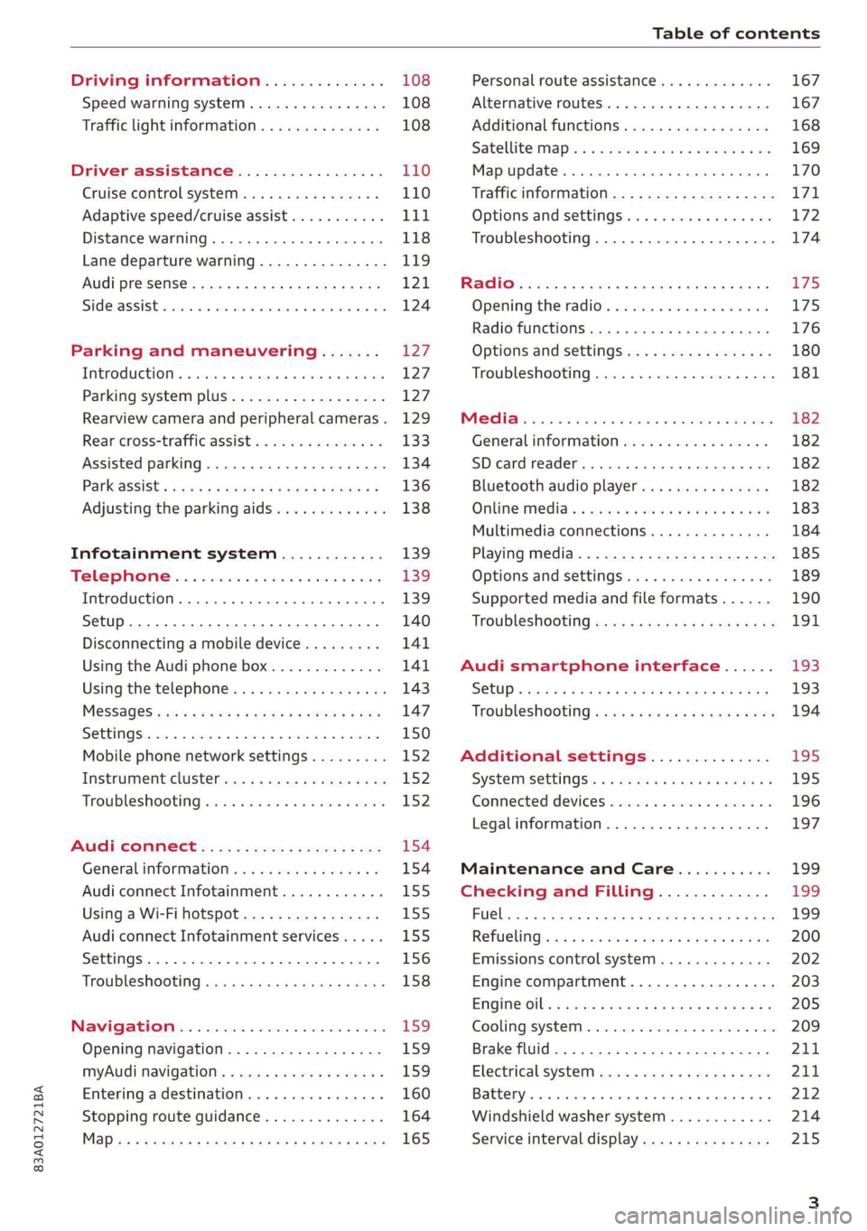
Table of contents
Driving information.............. 108
Speed warning system.........-..000- 108
Traffic light information.............. 108
Driver assistance................. 110
Cruise control systeM.......... 000 eee 110
Adaptive speed/cruise assist........... 111
Distance warning.................005 118
Lane departure warning............... 119
AUdi PrOSONsSe & seis + 2 mews 2» nee 2 oem 121
Side assist... 2... eee eee eee eee 124
Parking and maneuvering....... 127
IMtroduetion « x cicvers < e ersuens + x enavane oo saree 127
Parking system plus...............04. 127
Rearview camera and peripheral cameras. 129
Rear cross-traffic assist. ............-. 133
Assisted parking .............0.00005- 134
Parkassist': sexs « s neem sg aes + e wae 2 136
Adjusting the parking aids............. 138
Infotainment system............ 139
Telephone
Introduction
Setup..........
Disconnecting a mobile device......... 141
Using the Audi phone box............. 141
Using the telephone................0. 143
MESSAGES crus + ¢ ween ¢ 3 eeuen xy eee 4 2 ae 147
SOttiMGSicraice o saaneme « u eneneve © icameneies © eyeaeite 150
Mobile phone network settings......... 152
Instrument cluster.............2-.00. 152
Troubleshooting sais . eves 6 coarse es cae 152
AU CONMECE ces ¢ s xeee x 2 ews a i ee 154
Generalinformation................. 154
Audi connect Infotainment............ 155
Using a Wi-Fi hotspot................ 155
Audi connect Infotainment services..... 155
Settings............0 0.0000... 0000. 156
Troubleshooting sass ss eee ss ees ss ees 158
IIS VIG ABI. 5 cccccas os cones o enemies aoe 15S:
Opening navigation.................. 159
myAudi navigation.................0. 159
Entering adestination................ 160
Stopping route guidance.............. 164
Maize: = 2 sews ¢ 2 Som & eee Ee ees Fe eee 165
Personal route assistance............. 167
Alternative routes............02e000 167
Additional functions................. 168
Satellite mapiee e «sons e siemens ae aacens 2 4 ve 169
Map update............. 0. eee eee eee 170
Tratficintoritiationie: « : waa: xs seen 6 2 eu LZ)
Options and settings.............000e 172
Troubleshooting...............-.000- 174
R&GIO’: onic cs wea ss wens se eee & o Hews 175
Opening the radio................04. 175
Radio functions..................-4. 176
Options and settings...............0. 180
Troubleshooting.................0005 181
MG@Gias = acs ¢ = secs s © seme « s Seems so SeURS 182
General information ................. 182
SD card reader..........0.-..00 eee 182
Bluetooth audio player.............0. 182
Online Medias « ssi + exes ae omens oo veer 183
Multimedia connections.............. 184
Playing tedia. = s sees s 2 sees se wees ee 185
Options and settings...............0. 189
Supported media and file formats...... 190
Troubleshooting «ess 2s secu se vee ss ees 191
Audi smartphone interface...... 193
Setup... ee eee eee eee eee 193
Troubleshooting............ee eee eee 194
Additional settings.............. 195
SySteMm Settings: < saws ss sews se eee & 195
Connected devices............ 0 cee ee 196
Legal information................... 197
Maintenance and Care........... 199
Checking and Filling............. 199
FUGlaias s os08,8 & aay @ § aovon & § Sanne 8 OF eee 199
RePUCLING: is «a cms so ewes oe ese vB seen 200
Emissions control system............. 202
Engine compartment................. 203
EMGIMeiOils: acre « ¢ qaiea & © meee s 2 seNoN 8 Es 205
Cooling system. ............--00 00 eee 209
Brake fluid... . 0... eee eee eee 211
Electrical system.........--.0----05- 211
Battery. =o cecness « ommnaine « 0 omecwne 6 3 oats = oe 212
Windshield washer system............ 214
Service interval display............... 215
Page 9 of 280
83A012721BA
Quick access
Electromechanical parking brake
button ......... cece eee eee 90
Selector lever (automatic transmis-
SION) 26... eee ee eee eee 82
Audi phone Dox esessie so seas & 6 cere 141
START ENGINE STOP] button .... 80
Depending on equipment: ®®®
— Starting the engine when there is
amalfunction ............0005 81
—Ignition lock ................. 80
@3) Steering wheel adjustment ...... 56
@4 Lever for:
— Cruise control system ......... 110
— Adaptive cruise assist .......... 111
@) Data link connector for On Board
Diagnostic System (OBD) ........ 255
@8 Hood release .............0.0.. 204
@) Buttons for:
—~ CIGKES! mu: ¢ ¢ sem x ¢ etme Fo cee 43
—All-weather lights ............ 43
Luggage compartment lid button . 34
@3 Exterior mirror adjustment ...... 47
G0 Buttons for:
— Power windows .............. 38
—Child safety lock .............. 38
@ Tips
Some the equipment listed here is only instal-
led in certain models or is available as an op-
tion.
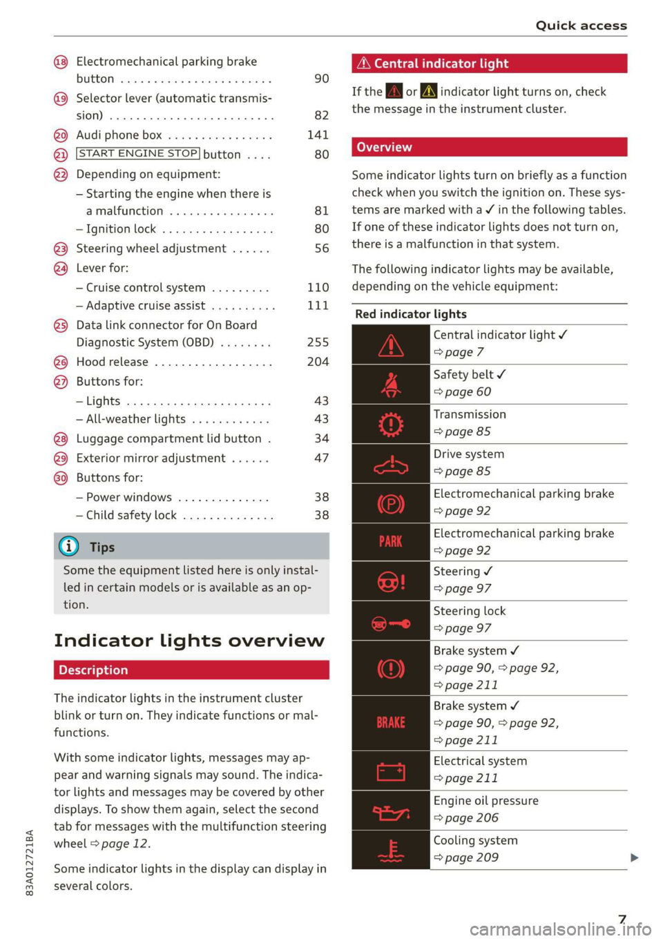
Indicator lights overview
The indicator lights in the instrument cluster
blink or turn on. They indicate functions or mal-
functions.
With some indicator lights, messages may ap-
pear and warning signals may sound. The indica-
tor lights and messages may be covered by other
displays. To show them again, select the second
tab for messages with the multifunction steering
wheel > page 12.
Some indicator lights in the display can display in
several colors.
A\ Central indicator light
If the wa or A indicator light turns on, check
the message in the instrument cluster.
Some indicator lights turn on briefly as a function
check
when you switch the ignition on. These sys-
tems are marked with a V in the following tables.
If one of these indicator lights does not turn on,
there is a malfunction in that system.
The following indicator lights may be available,
depending on the vehicle equipment:
Red indicator lights
Central indicator light ¥
=>page 7
Safety belt
=> page 60
Transmission
=> page 85
Drive system
=> page 85
Electromechanical parking brake
=> page 92
Electromechanical parking brake
=> page 92
Steering ¥
=> page 97
Steering lock
=> page 97
Brake system ¥
=> page 90, > page 92,
=> page 211
Brake system 4
=> page 90, > page 92,
=> page 211
Electrical system
=> page 211
Engine oil pressure
=> page 206
Cooling system
=> page 209
Page 10 of 280
Quick access
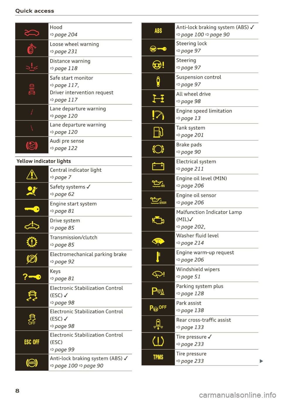
Hood
=> page 204
Loose wheel warning
=> page 231
Distance warning
=> page 118
Safe start monitor
= page 117,
Driver intervention request
=>page 117
Lane departure warning
=> page 120
Lane departure warning
=> page 120
Audi pre sense
=> page 122
Yellow indicator lights
Central indicator light
=> page 7
Safety systems ¥
=> page 62
Engine start system
=> page 81
Drive system
=> page 85
Transmission/clutch
=>page 85
Electromechanical parking brake
=> page 92
Keys
=> page 81
Electronic Stabilization Control
(ESC) ¥
=> page 98
Electronic Stabilization Control
(ESC) ¥
=> page 98
Electronic Stabilization Control
(ESC)
=> page 99
Anti-lock braking system (ABS) ¥
=> page 100 > page 90
Anti-lock braking system (ABS) /
= page 100 > page 90
Steering lock
=> page 97
Steering
=> page 97
Suspension control
=> page 97
All wheel drive
=> page 98
Engine speed limitation
=> page 13
Tank system
=> page 201
Brake pads
=> page 90
Electrical system
=> page 211
Engine oil level (MIN)
=> page 206
Engine oil sensor
=> page 206
Malfunction Indicator Lamp
(MIL)Y
=> page 202,
Washer fluid level
=>page 214
Engine warm-up request
=> page 206
Windshield wipers
=> page 51
Parking system plus
=> page 128
Park assist
=> page 138
Rear cross-traffic assist
=> page 133
Tire pressure ¥
=> page 233
Tire pressure
=> page 233
Page 11 of 280
83A012721BA
Quick access
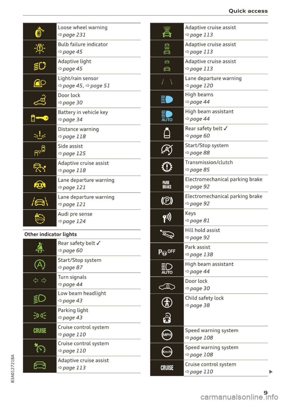
Loose wheel warning
> page 231
Bulb failure indicator
>page 45
Adaptive light
=>page45
Light/rain sensor
=> page 45,>page 51
Door lock
=> page 30
Battery in vehicle key
> page 34
Distance warning
>page 118
Side assist
>page 125
Adaptive cruise assist
=>page 118
Lane departure warning
=>page 121
Lane departure warning
>page 121
Audi pre sense
=> page 124
Other indicator lights
Rear safety belt ¥
=> page 60
Start/Stop system
=> page 87
Turn signals
=> page 44
Low beam headlight
=> page 43
Parking light
=> page 43
Cruise control system
=>page 110
Cruise control system
=>page
110
Adaptive cruise assist
=> page 113 ai
Adaptive cruise assist
= page 113
Adaptive cruise assist
= page 113
Adaptive cruise assist
= page 113
Lane departure warning
= page 120
High beams
=> page 44
High beam assistant
=> page 44
Rear safety belt ¥
=> page 60
Start/Stop system
=> page 88
Transmission/clutch
=> page 85
Electromechanical parking brake
=> page 92
Electromechanical parking brake
=> page 92
Keys
=> page 81
Hill hold assist
=> page 92
Park
assist
> page 138
High beam assistant
=> page 44
Door lock
=> page 30
Child safety lock
=> page 38
Speed warning system
= page 108
Speed warning system
= page 108
Cruise control system
=>page 110
Page 16 of 280
Instrument cluster
@) Note
The tachometer needle should only be in the
red zone briefly: Otherwise, this increases the
risk of engine damage. The location where the
red zone begins varies depending on the en-
gine.
Odometer
The trip odometer and odometer are displayed in
the status line ©) > page 11.
The trip odometer shows the distance driven
since it was last reset. It can be used to measure
short distances. The odometer shows the total
distance that the vehicle has been driven.
Resetting the trip odometer
> Select in the instrument cluster: Vehicle func-
tions tab > [=] button > Reset mi.
@) Tips
Distances are displayed in mi (miles) or km
(kilometers).
Outside temperature
display
The outside temperature is displayed in the sta-
tus line @) > page 11.
If your vehicle is stationary or if you are driving at
very low speeds, the temperature displayed in
the instrument cluster may be slightly higher
than the actual temperature outside due to heat
radiating from the engine.
At temperatures below 41 °F (+5 °C), a snowflake
symbol appears in front of the temperature dis-
play > A.
ZA\ WARNING
Do not assume the roads are free of ice based
on the outside temperature display. Be aware
that there may be ice on roads even when the
outside temperature is around 41 °F (+5 °C)
and that ice can increase the risk of accidents.
14
Vehicle functions
The trip computer is displayed in the first tab of
the driver information system. Additional vehicle
functions can be accessed depending on the vehi-
cle equipment.
> Press the =] button on the multifunction steer-
ing wheel.
— On-board computer > page 14
— Reduced display > page 13
— Reset trip odometer > page 14
On-board computer
Resetting values to zero
Requirement: the Consumption, Short-term
memory, or Long-term memory display must be
selected.
> To reset the values in one of the memories to
zero, press and hold the left thumbwheel on
the multifunction steering wheel for one sec-
ond, or
> Select in the instrument cluster: Vehicle func-
tions tab > [=] button > Reset mi.
Depending on the vehicle equipment, you can call
up the following displays in the on-board com-
puter one at a time by turning the left thumb-
wheel on the multifunction steering wheel:
— Time and date > page 195
— Average consumption > page 15
— Short-term memory overview
— Long-term memory overview
— Energy consumers > page 15
— Driver assistance
Short-term memory and long-term memory
The short-term memory collects driving informa-
tion from the time the ignition is switched on un-
tilit is switched off. If you continue driving within
two hours after switching the ignition off, the
new values will be included when calculating the
current trip information.
Page 26 of 280
Voice operation
Voice operation
General information
You can operate many functions in the vehicle
easily using voice commands.
Using the voice operation system effectively
> Speak clearly and distinctly at a normal volume.
Speak louder when driving faster.
> Emphasize the words in the commands evenly
and do not leave long pauses.
> Close the doors, the windows, and the sunroof*
to reduce background noise. Make sure that
passengers are not speaking when you are giv-
ing a voice command.
> Do not direct the vents toward the hands-free
microphone, which is in the roof headliner near
the front interior lights.
> Only the driver should speak to the system, be-
cause the handsfree microphone is aimed to-
ward this seating position.
ZA\ WARNING
— Direct your full attention to driving. As the
driver, you have complete responsibility for
safety in traffic. Only use the functions in
such a way that you always maintain com-
plete control over your vehicle in all traffic
situations.
— Do not use voice operation in emergencies
because your voice may change in stressful
situations. The system may take longer to
dial the number or may not be able to dial it
at all. Dial the emergency number manually.
@ Tips
There are no voice guidance* prompts when a
dialog is active.
24
Voice recognition system
Applies to: vehicles with voice recognition system
See
Dat)
Where is a
Connect
Diala
coy
Es
ea
cog
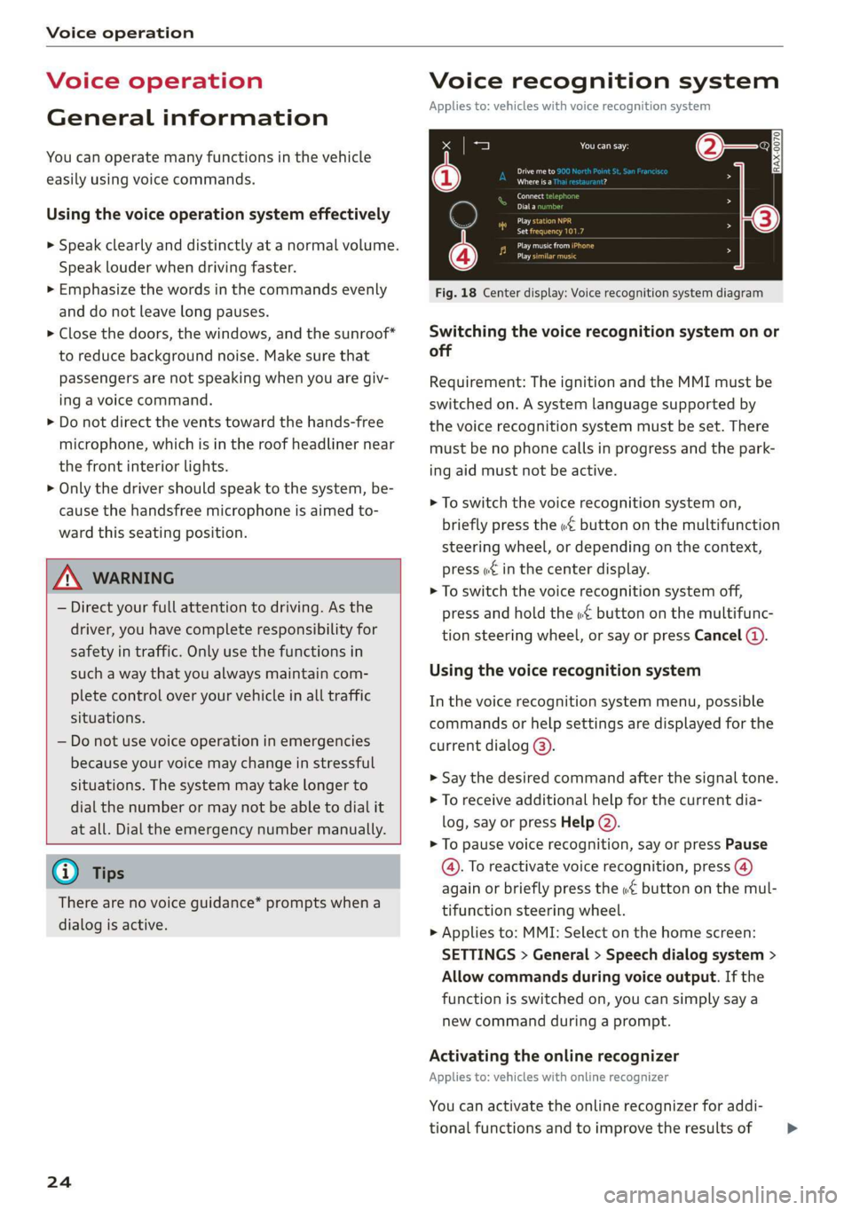
Fig. 18 Center display: Voice recognition system diagram
Switching the voice recognition system on or
off
Requirement: The ignition and the MMI must be
switched on. A system language supported by
the voice recognition system must be set. There
must be no phone calls in progress and the park-
ing aid must not be active.
> To switch the voice recognition system on,
briefly press the «€ button on the multifunction
steering wheel, or depending on the context,
press w£ in the center display.
> To switch the voice recognition system off,
press and hold the « button on the multifunc-
tion steering wheel, or say or press Cancel (a).
Using the voice recognition system
In the voice recognition system menu, possible
commands or help settings are displayed for the
current dialog @).
> Say the desired command after the signal tone.
> To receive additional help for the current dia-
log, say or press Help (2).
> To pause voice recognition, say or press Pause
@. To reactivate voice recognition, press (@)
again or briefly press the «€ button on the mul-
tifunction steering wheel.
> Applies to: MMI: Select on the home screen:
SETTINGS > General > Speech dialog system >
Allow commands during voice output. If the
function is switched on, you can simply say a
new command during a prompt.
Activating the online recognizer
Applies to: vehicles with online recognizer
You can activate the online recognizer for addi-
tional functions and to improve the results of >
Page 32 of 280
Opening and closing
When locking the vehicle with the central locking
switch, the following applies:
— The doors and the luggage compartment lid
cannot be opened from the outside for security
reasons, for example, to reduce the risk of un-
authorized entry while stopped at a light.
— The LED in the central locking switch turns on
when all doors are closed and locked.
— You can open the doors individually from the in-
side by pulling the door handle one time. To
open the rear doors individually, you must pull
the door handle twice.
— In the event of a crash with airbag deployment,
the doors unlock automatically to allow access
to the vehicle.
ZX, WARNING
— Follow the safety precautions > page 28.
— The central locking button works when the
ignition is switched off.
— The central locking switch is inoperative
when the vehicle is locked from the outside.
Messages
2 Driver's door: malfunction! Shift to P before
leaving vehicle. See owner's manual
There is a malfunction in the driver's door. Secure
the vehicle before exiting by selecting the “P” se-
lector lever position. Drive immediately to an au-
thorized Audi dealer or authorized Audi Service
Facility to have the malfunction repaired.
30
Mechanically unlocking and locking the
doors
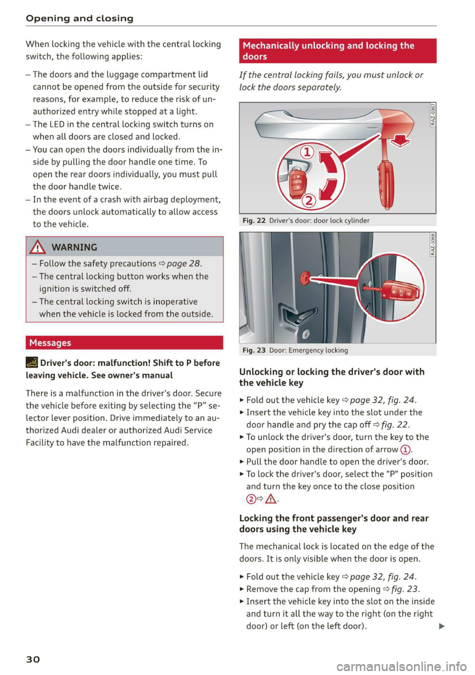
If the central locking fails, you must unlock or
lock the doors separately.
RAZ-0367,
Fig. 22 Driver's door: door lock cylinder
Fig. 23 Door: Emergency locking
Unlocking or locking the driver's door with
the vehicle key
> Fold out the vehicle key > page 32, fig. 24.
> Insert the vehicle key into the slot under the
door handle and pry the cap off > fig. 22.
> To unlock the driver's door, turn the key to the
open position in the direction of arrow @).
> Pull the door handle to open the driver's door.
> To lock the driver's door, select the "P" position
and turn the key once to the close position
@°A.
Locking the front passenger's door and rear
doors using the vehicle key
The mechanical lock is located on the edge of the
doors. It is only visible when the door is open.
> Fold out the vehicle key > page 32, fig. 24.
> Remove the cap from the opening > fig. 23.
> Insert the vehicle key into the slot on the inside
and turn it all the way to the right (on the right
door) or left (on the left door).
Page 34 of 280
Opening and closing
Keys
[RAZ-0369
RAZ-0728
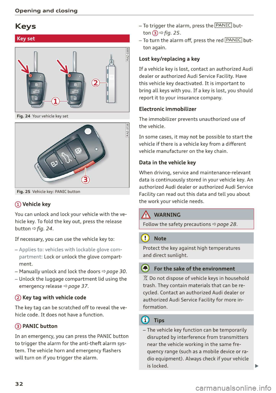
Fig. 25 Vehicle key: PANIC button
@ Vehicle key
You can unlock and lock your vehicle with the ve-
hicle key. To fold the key out, press the release
button © fig. 24.
If necessary, you can use the vehicle key to:
— Applies to: vehicles with lockable glove com-
partment: Lock or unlock the glove compart-
ment.
— Manually unlock and lock the doors > page 30.
— Unlock the luggage compartment lid using the
emergency release > page 37.
@ Key tag with vehicle code
The key tag can be scratched off to reveal the ve-
hicle code. It does not have a function.
@ PANIC button
In an emergency, you can press the PANIC button
to trigger the alarm for the anti-theft alarm sys-
tem. The vehicle horn and emergency flashers
will turn on if you trigger the alarm.
32
—To trigger the alarm, press the [PANIC] but-
ton@)® fig. 25.
—To turn the alarm off, press the red [PANIC] but-
ton again.
Lost key/replacing a key
If a vehicle key is lost, contact an authorized Audi
dealer or authorized Audi Service Facility. Have
this vehicle key deactivated. It is important to
bring all keys with you. If a key is lost, you should
report it to your insurance company.
Electronic immobilizer
The immobilizer prevents unauthorized use of
the vehicle.
In some cases, it may not be possible to start the
vehicle if there is a vehicle key from a different
vehicle manufacturer on the key chain.
Data in the vehicle key
When driving, service and maintenance-relevant
data is continuously stored in your vehicle key. An
authorized Audi dealer or authorized Audi Service
Facility can read out this data and tell you about
the work your vehicle needs.
Z\ WARNING
Follow the safety precautions > page 28.
@ Note
Protect the key against high temperatures
and direct sunlight.
@) For the sake of the environment
‘ Do not dispose of vehicle keys in household
trash. They contain materials that can be re-
cycled. Contact an authorized Audi dealer or
authorized Audi Service Facility for more in-
formation.
@ Tips
— The vehicle key function can be temporarily
disrupted by interference from transmitters
near the vehicle working in the same fre-
quency range (such as a mobile device or ra-
dio equipment). Always check if your vehicle
is locked.
Page 40 of 280
Opening and closing
Child safety lock
The child safety lock prevents the rear doors
from being opened from the inside and the rear
power windows from be operated.
RAZ-0372
B8W-0085
Fig. 33 Rear door: manual child safety lock
Vehicles with button #
Applies to: vehicles with power child safety locks
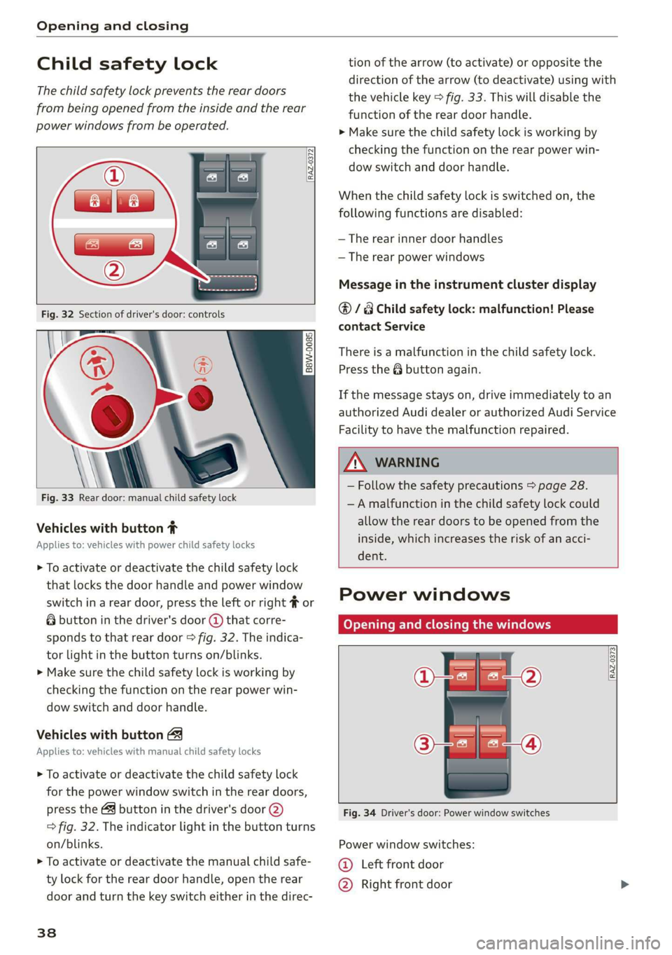
> To activate or deactivate the child safety lock
that locks the door handle and power window
switch in a rear door, press the left or right # or
& button in the driver's door @ that corre-
sponds to that rear door > fig. 32. The indica-
tor light in the button turns on/blinks.
> Make sure the child safety lock is working by
checking the function on the rear power win-
dow switch and door handle.
Vehicles with button
Applies to: vehicles with manual child safety locks
> To activate or deactivate the child safety lock
for the power window switch in the rear doors,
press the 4 button in the driver's door @)
> fig. 32. The indicator light in the button turns
on/blinks.
> To activate or deactivate the manual child safe-
ty lock for the rear door handle, open the rear
door and turn the key switch either in the direc-
38
tion of the arrow (to activate) or opposite the
direction of the arrow (to deactivate) using with
the vehicle key > fig. 33. This will disable the
function of the rear door handle.
> Make sure the child safety lock is working by
checking the function on the rear power win-
dow switch and door handle.
When the child safety lock is switched on, the
following functions are disabled:
— The rear inner door handles
— The rear power windows
Message in the instrument cluster display
@/8 Child safety lock: malfunction! Please
contact Service
There is a malfunction in the child safety lock.
Press the @ button again.
If the message stays on, drive immediately to an
authorized Audi dealer or authorized Audi Service
Facility to have the malfunction repaired.
ZA WARNING
— Follow the safety precautions > page 28.
—A malfunction in the child safety lock could
allow the rear doors to be opened from the
inside, which increases the risk of an acci-
dent.
Power windows
Opening and closing the windows
[RAZ-0373
Fig. 34 Driver's door: Power window switches
Power window switches:
©@ Left front door
@ Right front door
Page 42 of 280
Opening and closing
Operating the roof sunshade
Requirement: the roof must be closed.
> Opening and closing the sunshade: push the
switch in the headliner @) briefly toward the
rear or forward to the second level.
> Partially opening the sunshade: press the -&&
switch to the first level until the sunshade
reaches the desired position.
Operating the roof
> Tilting the roof: press the 4S switch in the
headliner briefly upward to the second level @).
> Closing the tilted roof: pull the A> switch
downward briefly to the second level.
> Opening the roof: slide the 2> switch back
briefly twice in a row to the second level @).
> Closing the roof: push the &> switch forward
briefly to the second level.
> Opening or closing partially: slide the A>
switch to the first level and hold it there until
the roof reaches the desired position.
Quick opening
You can also open the roof and roof sunshade in
one movement.
> Push the 4S switch back briefly to the second
level @).
Roof emergency closing
If an object is detected when closing, the roof
will open again automatically. In this case, you
can then close it with the power emergency clos-
ing function.
> Within five seconds after the sunroof opens au-
tomatically, pull the applicable button until the
roof is closed.
ZA WARNING
To reduce the risk of injury, always pay atten-
tion when closing the roof. Always switch the
ignition off and take the key with you when
leaving the vehicle.
D_ The possible number of hand-held transmitters depends
on the equipment.
40
Q®) Note
Always close the roof when you leave the vehi-
cle and when there is precipitation to reduce
the risk of damage to the interior equipment,
particularly the electronic equipment.
Gi) Tips
— After switching off the ignition, the roof and
sunshades can still be operated for several
minutes as long as neither of the front
doors are opened.
— It is not possible to open the roof when
temperatures are too low.
Garage door opener
Applies to: vehicles with garage door opener
i) + 3
2 4
go a
Fig. 36 Garage door opener: examples of usage for differ-
ent systems
With the garage door opener, you can activate
systems such as the garage doors, security sys-
tems or house lights from inside your vehicle.
These functions are operated in the MMI. Multi-
ple receivers can be programmed, which can con-
trol the functions of up to eight!) hand-held
transmitters.
ZA\ WARNING
— When operating or programming the garage
door opener, make sure that no people or >