fuel pump AUDI Q3 2020 Owners Manual
[x] Cancel search | Manufacturer: AUDI, Model Year: 2020, Model line: Q3, Model: AUDI Q3 2020Pages: 278, PDF Size: 72.66 MB
Page 200 of 278

Checking and Filling
— Do not use any gasoline mixture whose
composition cannot be identified.
— Audi does not assume any responsibility for
damage to the fuel system or for perform-
ance problems caused by using gasoline
mixtures different from those specified.
This type of damage also does not fall under
the New Vehicle Limited Warranty or under
the emissions control system warranty.
— If you notice a higher fuel consumption or
poor handling or performance problems due
to such gasoline mixtures, we recommend
fueling with unblended gasoline.
Gasoline additives
An important issue for many automobile manu-
facturers is combustion residue in the engine
that results from the use of certain fuels.
Although types of gasoline differ depending on
the manufacturer, there are similarities. Certain
substances in the gasoline may cause deposits in
the engine. Additives in the gasoline that should
keep the engine and fuel system clean do not all
function equally.
Audi recommends using TOP TIER Detergent Gas-
oline. For additional information on TOP TIER De-
tergent Gasoline, visit www.toptiergas.com.
If you use incorrect fuels over a long period of
time, the maximum engine performance may be
impaired by combustion residue.
@) Note
— Damage or malfunctions caused by the use
of incorrect types of gasoline are not cov-
ered by the New Vehicle Limited Warranty.
— Only gasoline additives that have been ap-
proved by Audi may be used.
198
Refueling
Fueling procedure
Fig. 136 Right rear side of the vehicle: opening the fuel
filler door
Fig. 137 Fuel filler door with attached fuel cap
The fuel filler door is unlocked or locked by the
central locking system.
>» Unlock the vehicle if necessary.
>» Press on the left side of the fuel filler door to
open it > fig. 136.
> Unscrew the tank cap counterclockwise.
> Place the cap from above on the open fuel filler
door > fig. 137.
> Insert the fuel pump nozzle all the way into the
fuel filler neck.
> Begin fueling. Once the fuel pump nozzle turns
off the first time, the fuel tank is full. Do not
continue fueling, or else the expansion space in
the tank will be filled with fuel.
> After the fuel pump has switched off, wait five
seconds before removing the nozzle to allow
the rest of the fuel to finish dripping into the
fuel tank.
> Turn the fuel cap clockwise until it clicks into
place.
> Close the fuel filler door and then press on the
left side until it latches.
Page 201 of 278

83A012721BB
Checking and Filling
The correct fuel type for your vehicle can be
found ona label located on the inside of the fuel
filler door. For additional information on fuel, see
=> page 197.
For the tank capacity in your vehicle, refer to the
Technical Data > page 262.
To reduce the risk of fuel leaking out or vapors
escaping, make sure that the fuel tank is closed
correctly. Otherwise the Ey indicator light will
turn on.
If the central locking system malfunctions, there
is a fuel filler door emergency release
=> page 200.
Messages
[il Tank system: malfunction! Please contact
Service
There is a malfunction in the fuel tank system.
Drive to an authorized Audi dealer or authorized
Audi Service Facility immediately to have the
malfunction corrected.
flying sparks. Sparks can start a fire when
refueling.
Z\ WARNING
Improper fueling procedures and improper
handling of fuel can lead to explosions, fires,
severe burns, and other injuries.
— Do not smoke. Keep away from open flames.
— The ignition must be switched off when re-
fueling.
— Mobile devices, radio devices, and other ra-
dio equipment should always be switched
off when refueling. Electromagnetic rays
could cause sparks and start a fire.
— If you do not insert the fuel pump nozzle all
the way into the filler tube, then fuel can
leak out. Spilled fuel can ignite and start a
fire.
— Never get into the vehicle when refueling. If
there is an exceptional situation where you
must enter the vehicle, close the door and
touch a metal surface before touching the
fuel pump nozzle again. This will reduce the
risk of electrostatic discharge that can cause
A WARNING
Transporting fuel containers inside the vehicle
is not recommended. Fuel could leak out of
the container and ignite, especially during an
accident. This can cause explosions, fires, and
injuries.
— Ifyou must transport fuel in a fuel contain-
er, note the following:
— Always place the fuel container on the
ground before filling. Never fill the fuel
container with fuel while it is inside or on
the vehicle. Electrostatic discharge can oc-
cur while refueling and the fuel vapors
could ignite.
— When using fuel containers made of met-
al, the fuel pump nozzle must always re-
main in contact with the container to re-
duce the risk of static charge.
— Insert the fuel pump nozzle as far as pos-
sible into the filler opening while refuel-
ing.
— Follow the applicable legal regulations in
the country where you are driving when
using, storing and transporting fuel con-
tainers.
— Make sure that the fuel container meets
the industry standards, for example ANSI
or ASTM F852-86.
) Depending on the engine and country
@) Note
— Remove fuel that has overflowed onto any
vehicle
components immediately to reduce
the risk of damage to the vehicle.
— Never drive until the fuel tank is completely
empty. The irregular supply of fuel that re-
sults from that can cause engine misfires.
Uncombusted fuel may enter the exhaust
system and increase the risk of damage to
the catalytic converter.
199
Page 252 of 278

Fuses and bulbs
— Some of the equipment listed in the follow-
ing tables applies only to certain model ver-
sions or certain optional equipment.
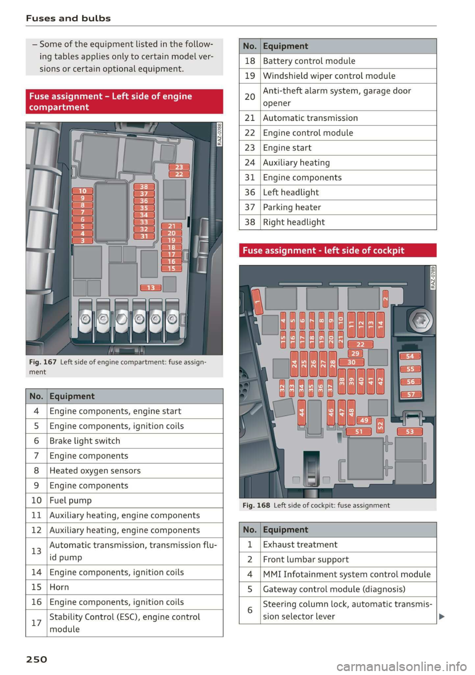
Fig. 167 Left side of engine compartment: fuse assign-
ment
No. | Equipment
Engine components, engine start
Engine components, ignition coils
Brake light switch
Engine components
Heated oxygen sensors
OlOAIN
I
DA/Mm|A
Engine components
10 | Fuel pump
11 | Auxiliary heating, engine components
No. Equipment
18 Battery control module
19 Windshield wiper control module
20
Anti-theft alarm system, garage door
opener
21 Automatic transmission
22 Engine control module
23 Engine start
24 Auxiliary heating
31 Engine components
36 Left headlight
37 Parking heater
38
Right headlight
Fig. 168 Left side of cockpit: fuse assignment
Stability Control (ESC), engine control
17
module
250
12 | Auxiliary heating, engine components No. | Equipment
13 Automatic transmission, transmission flu- 1 | Exhaust treatment
id pump 2 | Front lumbar support
14 | Engine components, ignition coils 4 |MMI Infotainment system control module
15 | Horn 5 | Gateway control module (diagnosis)
16 | Engine components, ignition coils 5 Steering column lock, automatic transmis-
sion selector lever