bulb AUDI Q5 2015 Owners Manual
[x] Cancel search | Manufacturer: AUDI, Model Year: 2015, Model line: Q5, Model: AUDI Q5 2015Pages: 302, PDF Size: 75.01 MB
Page 5 of 302
M N
co
a:
co
,...., \!) 1.1'1
N 1.1'1 ,....,
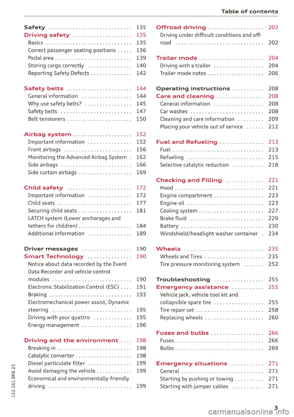
Safety . . . . . . . . . . . . . . . . . . . . . . . . . . . . 135
Driving safety . . . . . . . . . . . . . . . . . . . . 135
Basics . . . . . . . . . . . . . . . . . . . . . . . . . . . . . 135
Correct passenger seat ing positions . . . . . 136
Pedal area . . . . . . . . . . . . . . . . . . . . . . . . . . 139
Storing cargo correct ly . . . . . . . . . . . . . . . 140
Reporting Safety Defects . . . . . . . . . . . . . . 142
Safety belts . . . . . . . . . . . . . . . . . . . . . . 144
General information . . . . . . . . . . . . . . . . . 144
Why use safety belts? . . . . . . . . . . . . . . . . 145
Safety belts . . . . . . . . . . . . . . . . . . . . . . . . 147
Belt tensioners . . . . . . . . . . . . . . . . . . . . . . 150
Airbag system . . . . . . . . . . . . . . . . . . . . 152
Important information . . . . . . . . . . . . . . . 152
Front airbags . . . . . . . . . . . . . . . . . . . . . . . 156
Monito ring the Advanced Airbag System . 162
Side airbags . . . . . . . . . . . . . . . . . . . . . . . . 166
Side curtain airbags . . . . . . . . . . . . . . . . . . 169
Child safety . . . . . . . . . . . . . . . . . . . . . . 172
Important information . . . . . . . . . . . . . . . 172
Child seats .............. .... .. .. ... 177
Secur ing ch ild seats . . . . . . . . . . . . . . . . . . 181
LATCH system (Lower anchorages and
tethers for children) . . . . . . . . . . . . . . . . . . 184
Addit ional info rmation . . . . . . . . . . . . . . . 189
Driver messages . . . . . . . . . . . . . . . . . 190
Smart Technology . . . . . . . . . . . . . . . 190
Notice about data recorded by the Event
Data Recorder and vehicle control
modules . . . . . . . . . . . . . . . . . . . . . . . . . . . 190
E lect ronic Stabilization Control (ESC) . . . . 191
B raking . . . . . . . . . . . . . . . . . . . . . . . . . . . . 193
Electromechanica l power assist, Dynamic
steering . . . . . . . . . . . . . . . . . . . . . . . . . . . 195
Driving with your quattro . . . . . . . . . . . . . 195
Energy management . . . . . . . . . . . . . . . . . 196
Driving and the environment . . . . 198
Breaking in . . . . . . . . . . . . . . . . . . . . . . . . . 198
Cata lytic converter . . . . . . . . . . . . . . . . . . . 198
Diesel particu late filter . . . . . . . . . . . . . . . 199
Avoid damaging the vehicle . . . . . . . . . . . . 199
Econom ical and environmentally-friend ly
driving . . . . . . . . . . . . . . . . . . . . . . . . . . . . 199
Table of contents
Offroad driving . . . . . . . . . . . . . . . . . . .
202
Driving under difficult conditions and off-
road . . . . . . . . . . . . . . . . . . . . . . . . . . . . . . 202
Trailer mode . . . . . . . . . . . . . . . . . . . . . . 204
Driving with a trailer . . . . . . . . . . . . . . . . . 204
Tra iler mode notes . . . . . . . . . . . . . . . . . . . 206
Operating instructions . . . . . . . . . . . 208
Care and cleaning . . . . . . . . . . . . . . . . 208
General information . . . . . . . . . . . . . . . . . 208
Car washes . . . . . . . . . . . . . . . . . . . . . . . . . 208
Cleaning and care information . . . . . . . . . 209
Placing your vehicle out of service . . . . . . 212
Fuel and Refueling .......... ... .. 213
Fuel .. ..... ... .. .. ........ ...... ... 213
Refueling ... .. .. .. ... .. ... ..... .. .. 215
Selective catalytic reduction 218
Checking and Filling . . . . . . . . . . . . . 221
Hood . . . . . . . . . . . . . . . . . . . . . . . . . . . . . . 221
Eng ine compartm ent . . . . . . . . . . . . . . . . . 223
En gine oil . . . . . . . . . . . . . . . . . . . . . . . . . . 223
Cooling system . . . . . . . . . . . . . . . . . . . . . . 227
Brake fluid . . . . . . . . . . . . . . . . . . . . . . . . . 229
Battery . . . . . . . . . . . . . . . . . . . . . . . . . . . . 230
Windshield/headlight washer container 234
Wheels .. .... .. .. ... ........ .. .. .. 235
Wheels and Tires . . . . . . . . . . . . . . . . . . . . 235
Tire pressure monitoring system . . . . . . . 252
Troubleshooting . . . . . . . . . . . . . . . . . 255
Emergency assistance . . . . . . . . . . . 255
Vehicle jack, vehicle tool kit and
collapsib le spare tire . . . . . . . . . . . . . . . . . 255
Tire repair set . . . . . . . . . . . . . . . . . . . . . . . 258
Replacing wheels . . . . . . . . . . . . . . . . . . . . 260
Fuses and bulbs . . . . . . . . . . . . . . . . . . 266
Fuses. ...... .. .. .. ... .. ... ..... .. .. 266
Bulbs. . . . . . . . . . . . . . . . . . . . . . . . . . . . . . 269
Emergency situations . . . . . . . . . . . . 271
General . . . . . . . . . . . . . . . . . . . . . . . . . . . . 271
Starting by pushing or towing . . . . . . . . . . 271
Starting with jumper cables . . . . . . . . . . . 27 1
3
Page 18 of 302
Instruments and indicator lights
still fu nction with their normal power, but A BS is
not active .
D rive to y our a uthorize d Au di d eale r o r q ual ified
wo rkshop immediately to have the ma lf u nction
corrected .
A WARNING
If the .. (USA models) . (Canada mod
els) brake system indicator light turns on to
gether with the ABS and ESC indicator lights ,
the ABS/ESC regulating function may have
failed . Functions that stabilize the vehicle are
no longer available . Th is could cause the vehi
cle to swerve and increase the risk of sliding .
Dr ive caref ully to the nearest autho rized Aud i
de aler or o ther qualified wor kshop and have
t he malfunction corrected .
(D Tips
For addit iona l information on ESC and ABS,
refer to
¢ page 191.
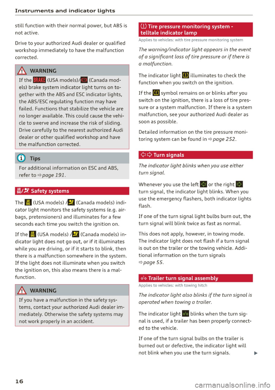
CJ};/ !f Safety systems
-
The II (USA models) a (Cana da models) indi
cator light monito rs the safety systems (e .g . air
bags, pretensione rs) and illuminates for a few
seconds each time you switch t he ignition on.
If t h e II (U SA mode ls) a (Canad a models) in
d icator light does not go out, or if it i llum inates
while you are driving, or if it starts to blink, then
there is a malfunction somewhe re in the system.
I f the light does not ill uminate when you switch
the igni tion on, this also means there is a mal
function .
A WARNING
If you have a mal func tion in the safety sys
t ems, contact your authorized A udi dealer im
media tely. Othe rwise the safety system s may
no t w or k properly in an a cci den t.
16
ill Tire pressure monitoring system -
telltale indicator lamp
Applies to vehicles: with tire pressure monitoring system
The warning/indicator light appears in the event
of a signifi cant loss of tire pressure or if there is
a malfunction.
The ind icator light RI] illumi nates to check the
func tion when yo u sw itch on t he ign it io n.
If the
RI] symbo l rema ins on or blinks after you
switch on the ignition, the re is a loss of tire pres
su re or a system ma lfunction .
If there is a system
malfunction, see your author ized Audi dealer as
soon as possib le.
Deta iled info rmat ion on the tire pressure mo ni
tor ing system ca n be found in
¢page 252.
¢¢Turn signals
The indicator light blinks when you use either
turn signal .
Whenever you use the left B or the right R
turn s ignal, the indicator light blinks . When you
use the eme rgency flashers, bot h in d icator lights
flash .
If one of the turn signa l ligh t bulbs burn out, the
turn s ignal will b link twice as fast as normal.
This does not apply, however, in towing mode.
The ind icator light does not flash if a turn signa l
i s out on the tra iler or the towing veh icle. Add i
tiona l information on the turn signa ls
¢ page 55.
¢1.~ Trailer turn signal assembly
Applies to vehicles: with towing hitch
The indicator light also blinks if the turn signal is
operated when towing a trailer .
The indicator light . blinks when the t urn s ig
nal is used, if a trai ler has been properly co nnect
ed to the ve hicle .
If one of the tu rn signa l bulbs on the t railer is
burned out or defective, the ind icator light will
not blink when you use the turn signa ls.
Page 33 of 302
M N
co
a:
co
,...., \!) 1.1'1
N 1.1'1 ,....,
~ Do not turn the engine off.
~ Drive immediately to an authorized Audi dealer
to have the malfunction corrected .
If there is a malfunction in the e lectronic ignition
l ock, the ignition cannot be turned off . Drive im
mediately to an authorized service facility to have
the cause of the ma lfunction corrected.
On vehicles with Convenience key*, the engine
should not be switched off using the Start/Stop
button because the engine cannot be started
again after the ignition has been switched off.
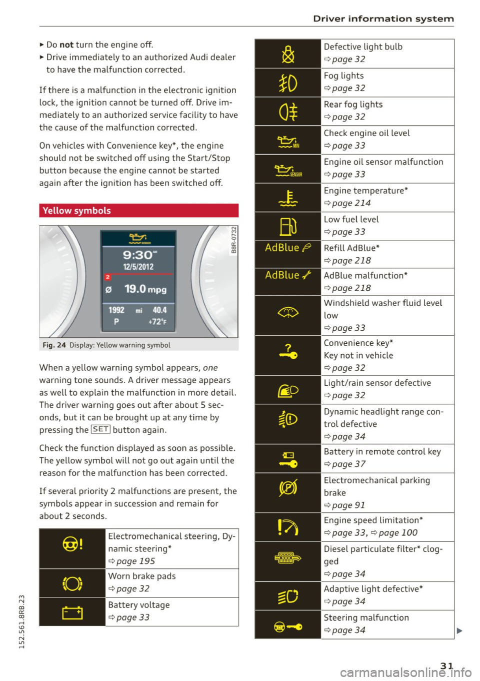
Yellow symbols
Fig. 24 Display: Ye llow warn ing symbo l
N M
9 a: a, a,
When a ye llow warning symbol appears, one
warning tone so unds . A driver message appears
as we ll to exp la in the malf unction in more detail.
The driver warning goes out after about S sec
onds, but it can be brought up at any time by press ing t he
ISETI button again.
Check the function d isp layed as soon as possible.
The yellow symbol w ill not go out aga in until the
reason for the malfunction has been corrected.
If several priority 2 malfunctions are present, the
symbols appear in succession and remain for
about 2 seconds.
Elect rom echan ica l steering, Dy
namic steering*
¢page 195
Worn brake pads
¢page32
Battery voltage
¢page33
Driver information system
Defective light bulb
¢ page 32
Fog lights
¢page 32
Rear fog lights
¢page 32
Check engine oil leve l
¢page 33
Engine oil sensor malf unc tion
¢page 33
Engine temperature*
¢page 214
Low fuel level
¢page 33
Refill Ad Blue*
¢page 218
AdBlue malfunction *
¢page 218
Windshield washer fluid level
low
¢page 33
Convenience key*
Key not in veh icle
¢ page 32
Light/rain sensor defective
¢page 32
Dynamic headlight range con
trol defective
¢ page 34
Battery in remote control key
¢page 37
Electromechanical parking
brake
¢page 91
Engine speed lim itation*
¢ page 33, ¢page 100
Diesel particulate filter* clog
ged
¢ page 34
Adaptive light defective*
¢page 34
Steering malfunction
¢page 34
31
Page 34 of 302
Driver inform ation system
Ignition lock malfunction
<=>page 34
Adapt ive dampers*
c:> page 34
W indshield wiper defective
c:>page34
Tire pressure monitoring sys
tem*
Loss of t i re pressure
c:>page253
Tire pressure monitoring sys
tem* System not avai lab le
c:>page253
Automatic t ransmission ma l
function
c:> page 12 7
H ybr id drive*
<=> page 100
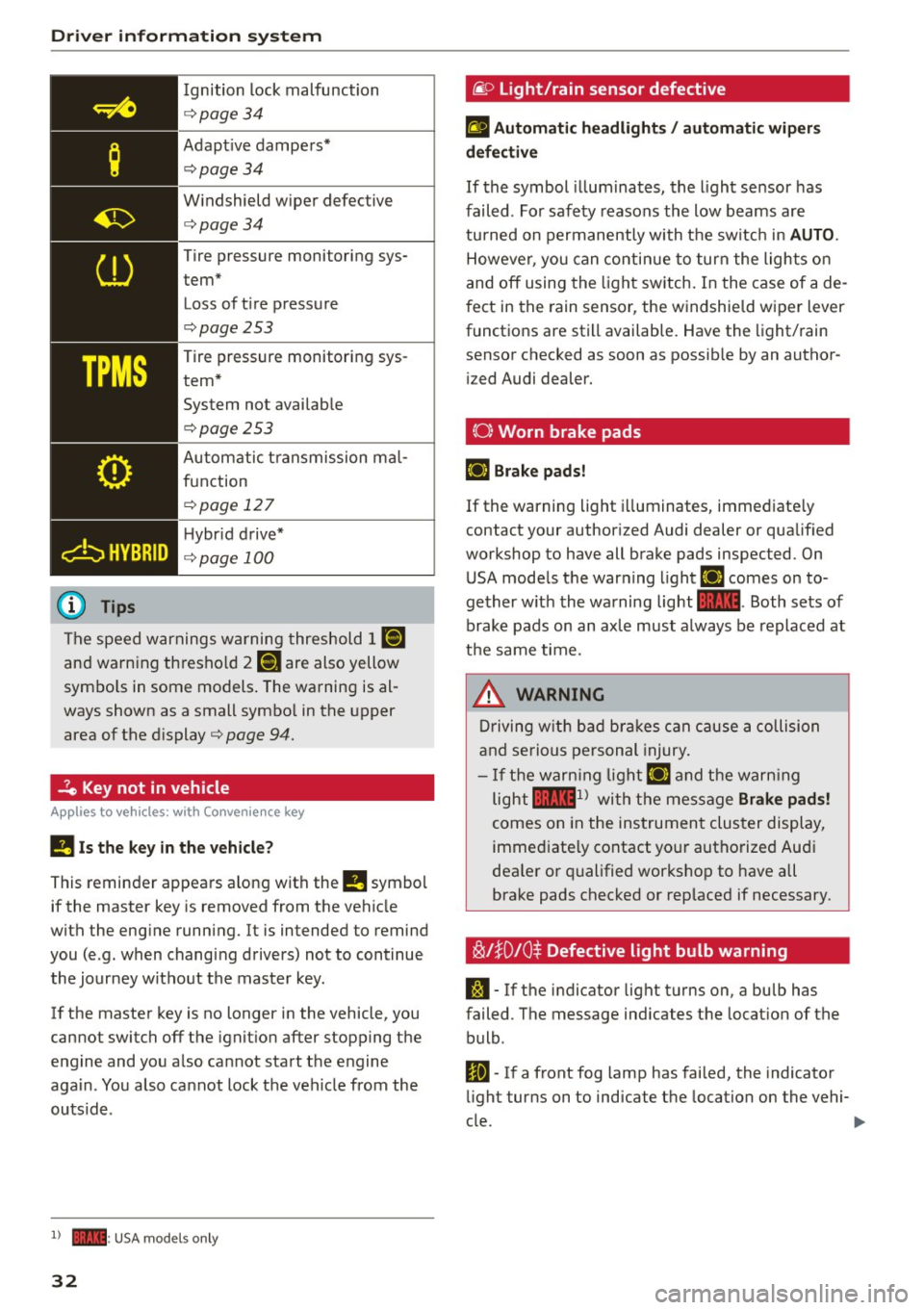
The speed warnings warning threshold J IIIIJ
and warning thresho ld 2 llH are also yellow
symbo ls in some models . The warning is al
ways shown as a small symbo l in the upper
area of the d isplay
c:> page 94.
-?e Key not in vehicle
Applies to veh icles: w ith Convenience key
II Is the key in the vehicle ?
This reminder appears along with the II symbol
if the master key is removed from the vehicle
with the eng ine running. It is intended to remind
you (e .g. when changing drivers) not to continue
the journey without the master key .
If the master key is no longer in the vehicle, you
cannot switch off the ignit ion after stopping the
e ngine and you a lso cannot start the engine
aga in . You also cannot lock the veh icle from the
outsid e.
l ) - : USA models only
32
@ Light/rain sensor defective
£1 Automati c he adlight s/ auto mati c wi per s
defective
If the symbol illum inates, the light sensor has
failed. For safety reasons the low beams are
tu rned on permanently with the sw itch in
AUTO .
However, you can contin ue to turn the lights on
and off using the light sw itch. In the case of a de
f ect in the rain sensor, the windshie ld wiper lever
functions are still available. Have the light/rain
sensor checked as soon as possib le by an author
i zed Audi dealer.
(0) Worn brake pads
E+J Brake pad s!
If the warning light i lluminates, immediate ly
contact your author ized Audi dealer or qualified
workshop to have all brake pads inspected. On
USA mode ls the warning light
E+J comes on to
gether w ith the warning light
1111 . Both sets of
brake pads on an axle must always be replaced at
t h e same time.
.&_ WARNING
Driving w ith bad bra kes can cause a collision
and serious personal injury.
- If the warn ing lig ht E+J and the warn ing
light
llll1l with the message Brake pad s!
comes on in the instrument cluster display,
immed iate ly contact yo ur authorized Aud i
dea le r or q ualified workshop to have all
brake pads checked or rep laced if necessary.
~l}D10$ Defective light bulb warning
S:1 -If the indicator light turns on, a bulb has
failed. The message indicates the location of the
bulb .
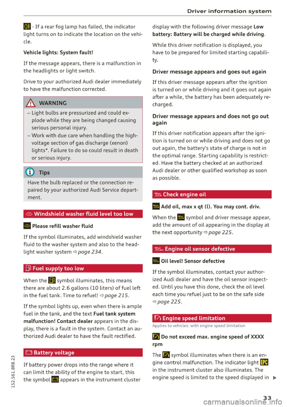
Im-If a front fog lamp has fai led, the indicator
li ght turns on to indicate the location on the vehi-
cle.
~
Page 35 of 302
M N
co
a:
co
,...., \!) ..,.,
N ..,., ,....,
IJ-If a rea r fog lamp has failed , the indicator
light turns on to indicate the location on the vehi
cle.
Vehi cle light s: Sy stem fault!
If the message appea rs, there is a malfunct ion in
the head lights or light switch.
Drive to your authorized Aud i dea le r immediately
to have the malfunction corrected .
A WARNING
-Light bu lbs are pressurized and could ex
plode whi le they a re being changed causing
serious persona l injury.
-
- Wor k w ith due care when handling the high
voltage section of gas discharge (xenon) l igh ts *. Failure to do so could result in death
o r serious injury.
@ Tips
Have the bulb replaced or the connection re
pa ired by your authorized Audi Serv ice depart
ment.
<:;::> Windshield washer flu id level too low
llt Plea se refill wa sher fluid
If the symbol illuminates, add windshield washe r
fluid to the washer system and also to the head
light washer system¢
page 234 .
Bil Fuel supply too low
When the D symbol i llum inates, this means
there are about 2 .6 gallons ( 10 liters) of fue l left
in the fuel tank. Time to refuel!
¢ page 215.
If the symbo l lights up, even when the re is ample
fue l in the tank, and the text
Fuel tank sy stem
malfun ction! Contact dealer
appears in the dis
p lay, there is a fau lt in the system . Contact an a u
thor ized Audi dealer to have the fault rectified.
D Battery voltage
If battery power drops into the range where it
can limit the abil ity of the engine to sta rt, th is
the symbo l(•) ::ippears in the instrument cluster
Driver information s ystem
display with the following driver message Lo w
batter y: Batte ry will be charged while d riving.
While t his d river no tification is disp layed, you
have to be prepa red fo r limited star ting capabili
ty .
Driver message appears and goes out again
If this drive r message appears after the ign ition
is tur ned on or while d riving a nd it goes ou t again
after a wh ile, the ba ttery has been adequa tely re
charged .
Driver message appears and does not go out
again
If this drive r notific ation appea rs after the ign i
t ion is tu rned on or while dr iv ing and does not go
out again, the battery's state of charge is no t in
the optimal range. Start ing capability is restrict
ed. Have the battery checked at an authorized
Audi dealer or other qualified workshop as soon as possible.
~ Check engine oil
II Add oil, ma x x qt (l) . You may cont . driv .
When the Ill symbol and dr iver message appear,
add the amount of oil appear ing in the disp lay at
the next opportunity ¢
page 225.
'l:7;,.. Engine oil sensor defective
• Oil le vel! Sen sor defective
If the symbol illuminates, contact yo ur author
ized Audi dealer and have the oil sensor inspect
ed . Until you have this done, check the oil level
each time you ref uel just to be on the safe s ide
¢ page 225.
!? Engine speed limitation
Applies to vehicles: with engine speed limitation
II! Do not ex ce ed max . engine speed of XXXX
rpm
T he II! symbol illuminates when there is a n en
gine co ntro l malfunction . The indicato r light ~
i n t he i nstr ument cluster also illum inates. The
engine speed is limited to the speed displayed in .,,.
33
Page 234 of 302
Checking and Filling
-Do not interchange the positive and nega
tive cables .
- When working on the battery, be sure not to
short-circuit the terminals with tools or oth
er metal objects. This would cause the bat
tery to heat up very quickly, which could
lead to damage or explosion and personal
injury .
- When a battery is charged, it produces hy
drogen gas which is explosive and could
cause personal injury.
- Always keep the battery well out of the
reach of children .
- Before work is done on the electrical sys
tem, disconnect the negative ground cable .
- Before performing any work on the electri
cal system, switch off the engine and igni
tion as well as any electrical equipment. The
negative cable on the battery must be dis
connected. If you are just going to replace a
light bulb, then it is enough to switch off
the lights.
- Before disconnecting the battery, switch off
the anti-theft alarm system! Otherwise you
will set off the alarm.
- When disconnecting the battery, first dis
connect the negative cable and then the
positive cable.
- Before reconnecting the battery, make sure
all electrical consumers are switched off. Re
connect the positive cable first and then the
negative cable . Never interchange the ca
bles -this could start a fire!
- Never charge a frozen or a thawed-out bat
tery. It could explode! If a battery has fro
z en, then it must be replaced . A discharged
battery can freeze over at 32°F (O°C).
- Make sure the vent hose is always attached
to the opening on the side of the battery .
- Never use batteries which are damaged.
There is the danger of an explosion! Always
replace a damaged battery.
A WARNING
California Proposition 65 Warning:
- Battery posts, terminals and related acces
sories contain lead and lead compounds,
232
chemicals known to the State of California
to cause cancer and reproductive problems.
Wash hands after handling.
(D Note
- Do not disconnect the vehicle battery when
the ignition is switched on or when the en
gine is running, otherwise , you will damage
electronic components in the electrical sys
tem .
- If your vehicle is going to stand for a long
period of time without being driven, protect
the battery from "freezing", otherwise it
will be damaged and will then have to be re placed.
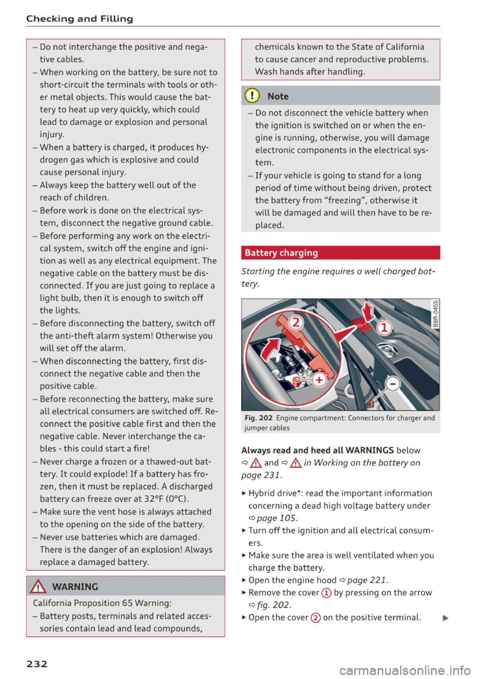
Battery charging
Starting the engine requires a well charged battery .
Fig. 202 Engin e compar tment : Co nnec tors fo r char ger and
jumper cables
Always read and heed all WARNINGS below
¢ .&. and
¢.&. in Working on the battery on
page 231 .
.. Hybrid drive*: read the important information
concerning a dead high voltage battery under
¢ page 105.
.. Turn off the ignition and all electrical consum
ers.
.. Make sure the area is well ventilated when you
charge the battery .
.. Open the engine hood
¢ page 221.
.. Remove the cover(!) by pressing on the arrow
¢fig. 202 .
.. Open the cover @on the positive terminal. .,.
Page 268 of 302
Fuses and bulbs
Fuses and bulbs
Fuses
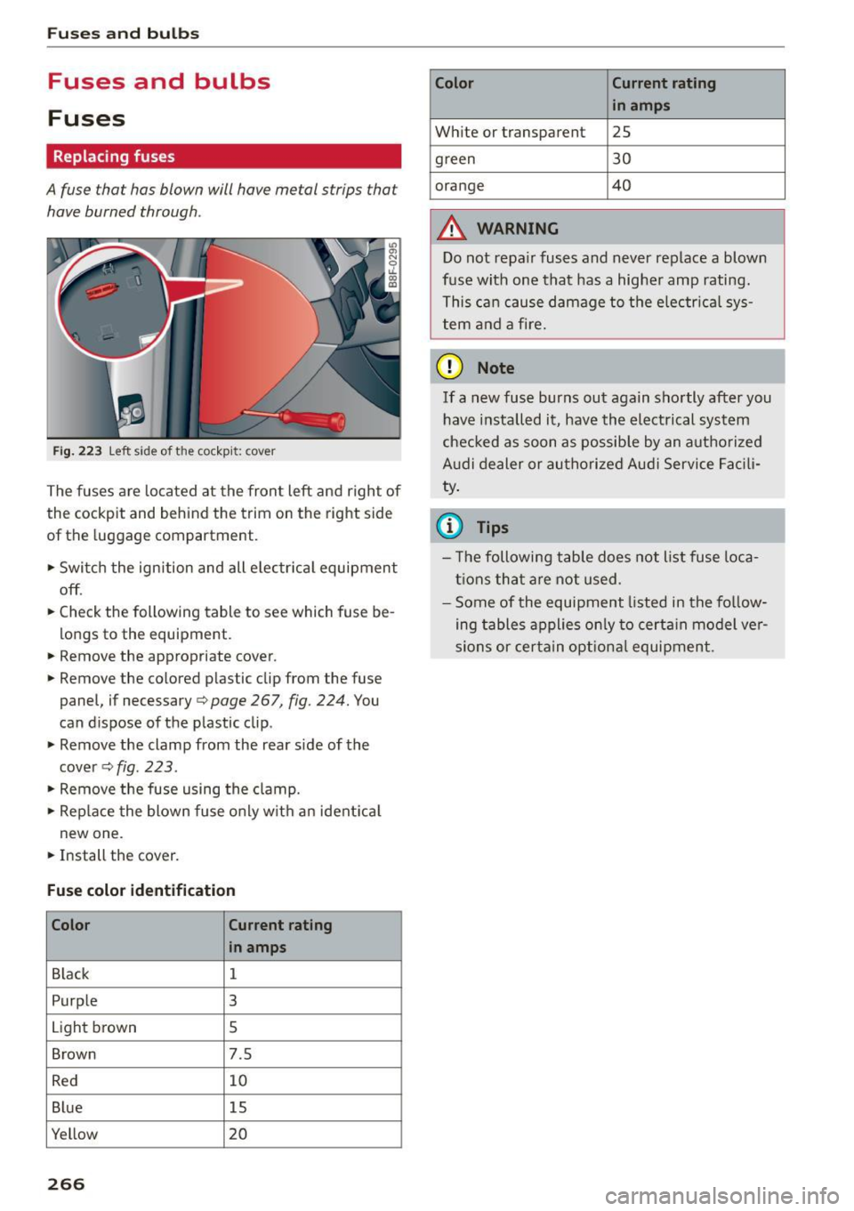
Replacing fuses
A fuse that has blown will have me tal strips that
have burned through.
Fig. 2 23 Left side of the coc kp it: c ove r
The fuses a re located at the fron t left and right of
the cockpit and behind the trim on the right side
of the luggage compartment.
• Swi tc h the ign ition and all e lec trica l equipment
off .
• Check the following table to see which fuse be
longs to the equipment.
• Remove the appropriate cover.
~ Remove the colored p lastic clip from the fuse
panel, if necessary ¢
page 267, fig. 224. You
can d ispose of the p lastic clip .
• Remove the clamp from the rear side of the
c over ¢
fig. 223 .
• Remove the fuse using the clamp.
• Rep lace the blow n fuse o nly w it h a n ident ica l
new one.
• Install the cover .
Fuse color identification
Color Current
rating
in amps
B lack 1
Purp le
3
Light brown
s
Brown 7.5
R ed 10
B lue 15
Yellow 20
266
Color Current rating
in amps
W hite or transparent
2S
green 30
orange 40
A WARNING
Do not repair fuses and never replace a blown
fuse with one tha t has a hig her amp rating.
T hi s ca n cau se da mage to the e lec trica l sy s
tem and a fire .
(D Note
If a new fuse burns out again sho rtly after you
have install ed it, have th e electri cal syst em
che cked as soon as possib le by an autho rize d
A udi dealer or au tho riz ed Au di Service Facili
ty .
{i) Tips
- T he followi ng tab le does not list fuse loca
tion s that a re n ot u sed .
- Some of the e quipment listed in the fo llow
ing table s applies on ly to cert ain model ve r
si ons or certain op tion al equi pment .
Page 269 of 302

M N
co ~ co
rl I.O
"' N
"' rl
Left cockpit fuse assignment
Fig. 224 Left side of the cockpit: fuse panel with plastic
clip
Fuse panel @ (black )
No. Equipment
1 Dynamic steering
2 ESC control module
A/C system pressure sensor, electrome-
3 chanical park
ing brake, Homelink, auto-
matic dimming interior rearview mirror, air
quality/outside air sensor, ESC button
5 Sound
actuator/exhaust sound tuning
6 Headlight range contro l/cornering light
7 Headlight (cornering light)
Control modu les (e lectromechanical park-
8 ing brake, shock absorber, quattro Sport,
trailer hitch), DCDC converter
9
Adaptive cruise control or high voltage
battery (hybrid drive)
11 Side assist
12 Headlight range control, parking system
13 Airbag
14 Rear w iper
15 Auxi
liary fuse (instrument panel)
1 6 Auxiliary fuse terminal 15 (engine area) Fuses
and bulbs
Fuse panel @ (brown)
No . Equipment
1 Electric exhaust door
2 Brake light sensor or brake pedal
move-
ment sensor (hybr id drive)
3 Fuel pump
4 AdBlue pumps
or brake booster power
supply (hybrid dr ive)
5 Left seat heating with/without seat venti-
lation
6 ESC
7 Horn
8 Left
front door (window regulator, central
locking, mirror, switch, lighting)
9 Wiper motor
10 ESC
11 Left
rear door (window regu lator, switch,
lighting)
12 Rain and light sensor
Fu
se panel © (re d)
No . Equipment
3 Lumbar support
4 Dynamic steering
5 Climatized cupholder
6 Windshie
ld washer system, headlamp
washer system
7 Vehicle electr ical system control module 1
8 Vehicle e
lectrica l system control module 1
9 Panorama sunroof
10 Vehicle e lectrica l system control module 1
11 Sun shade (pano rama sunroof)
12 Anti-theft a
larm system
267
Page 270 of 302
Fuses and bulbs
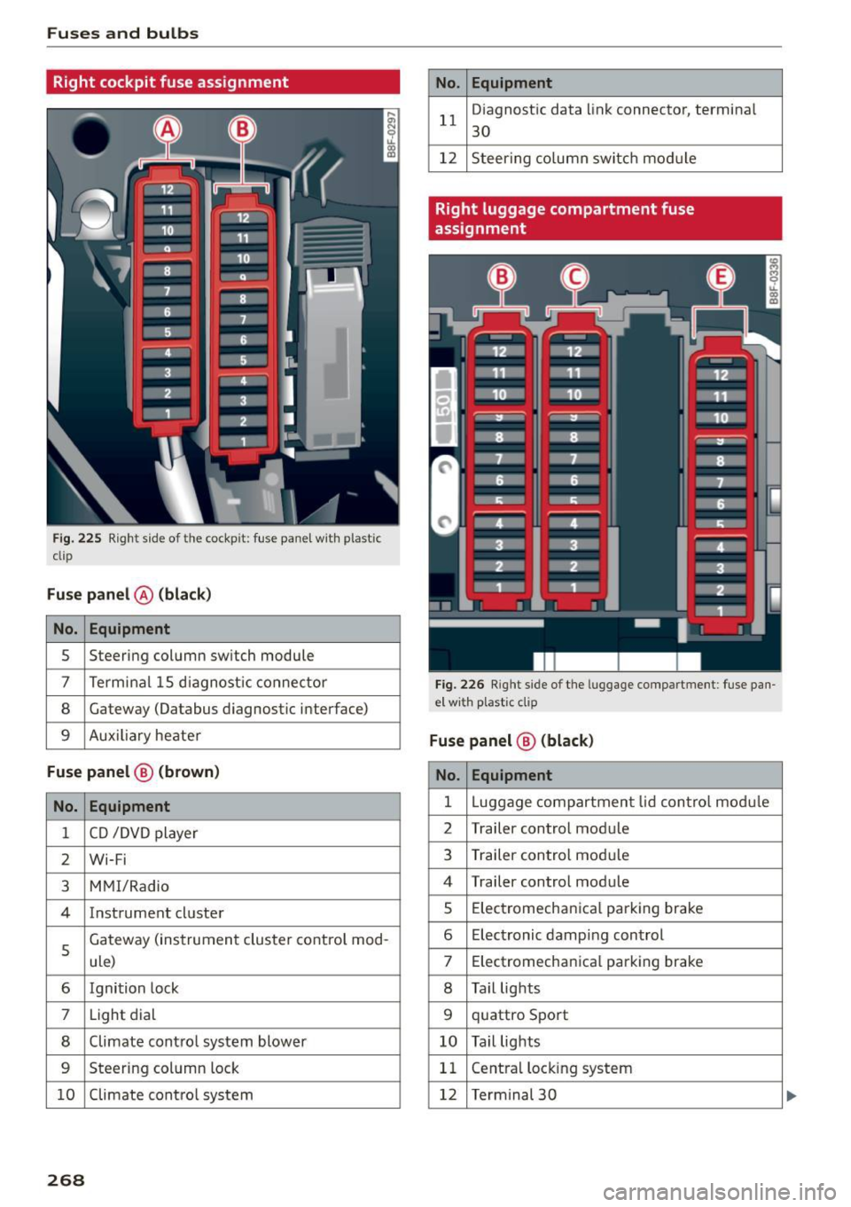
Right cockpit fuse assignment
Fig . 225 Right s ide of the cockpit: fuse panel wit h plastic
clip
Fuse panel @ (black)
No. Equipment
5 Steering column sw
itch module
7 Terminal 15 diagnostic connector
8 Gateway (Oatabus diagnostic interface)
9 Auxiliary heater
Fuse panel@ (brown)
No. Equipment
1 CD /DVD player
2 Wi-Fi
3 MM I/Radio
4 Instrument cluster
5
Gateway (instrument cluster control mod-
ule)
6 Ignition lock
7 Light dial
8 Climate control system blower
9 Steering column lock
10 Climate control system
268
No. Equipment
11 D
iagnost ic data link connecto r, terminal
30
12 Steering column switch module
Right luggage compartment fuse
assignment
Fig. 226 Righ t side of the lu ggage compartment: fuse pan
e l w ith plastic clip
Fuse panel @ (black)
No. Equipment
1 Luggag e compartm ent lid control module
2 Trailer contro
l module
3 Trailer con trol module
4 Trailer control module
s Elec trom echanica l parking brake
6 E lectronic damping control
7 Electromechanical parking brake
8 Tail lights
9 quattro Sport
10 Tail lights
11 Central locking
system
12 Termina l 30
Page 271 of 302
M N
co
a:
co
,...., \!) 1.1'1
N 1.1'1 ,....,
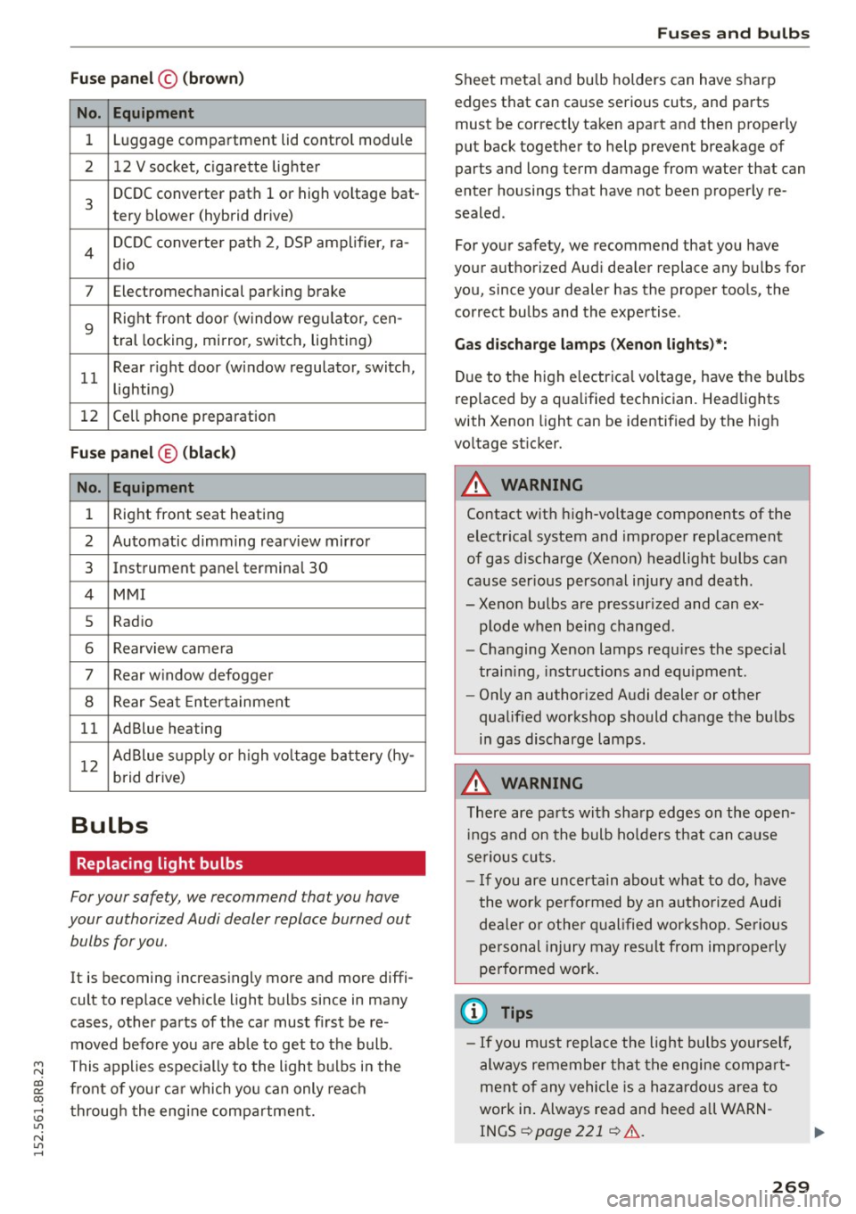
Fuse panel© (brown)
No. Equipment
1 Luggage compartment lid control module
2 12 V socket, c igarette lighter
3
DCDC converter path 1 or high vo ltage bat-
tery blower (hybrid drive)
4 DCDC converter path 2, DSP amplifier, ra-
dio
7 Electromechanical parking brake
9
Right front doo r (window reg ulator, cen-
tral locking, mirror, switch, lighting)
11 Rear r
ight door (window regulator, switch,
lighting)
12 Cell phone
preparation
Fuse panel ® (black)
No. Equipment
1 Right front seat heating
2 Automatic dimming rearview mirror
3 Instrument panel terminal 30
4 MMI
5 Radio
6 Rearview came
ra
7 Rear window defogger
8 Rear Seat Entertainment
11 AdBlue heating
12 Ad
Blue supply or high voltage battery (hy-
brid drive)
Bulbs
Replacing light bulbs
For your safety, we recommend that you have
your authorized Audi dealer replace burned out bulbs for you.
It is becoming increasingly more and more diffi
cult to replace vehicle light bulbs since in many
cases, other parts of the car must first be re
moved before you are ab le to get to the bulb.
This applies espec ially to the light bulbs in the
front of you r car which you can only reach
through the engine compartment.
Fuses and bulbs
Sheet metal and bulb holders can have sharp
edges that can cause serious cuts, and parts
must be correctly taken apart and then properly
put back together to help prevent breakage of
parts and long term damage from water that can
enter housings that have not been proper ly re
sealed .
For your safety, we recommend that you have
your authorized Aud i dealer replace any bulbs for
you, since your dealer has the proper too ls, the
correct bulbs and the expertise .
Gas discharge lamps (Xenon lights )*:
Due to the high e lectrica l voltage, have the bulbs
replaced by a qualified technician. Headlights
with Xenon light can be identif ied by the high
vo ltage sticker.
A WARNING
Contact with high-voltage components of the
electr ical system and improper replacement
of gas discharge (Xenon) headlight bulbs can
cause ser ious personal injury and death.
- Xenon bulbs are pressur ized and can ex-
plode when being changed.
- Changing Xenon lamps requ ires the special
train ing, instructions and equipment.
- Only an authorized Audi dealer or other
qualified workshop should change the bulbs
in gas discharge lamps.
A WARNING "'--
There are parts with sharp edges on the open-
in gs and on the bulb holders that can cause
serious cuts.
- If you are uncertain about what to do, have
the wor k performed by an authorized Aud i
dealer or other qualified workshop. Serious
personal injury may resu lt from improperly
performed work .
(D Tips
-If you must replace the light bulbs yourself,
always remember that the engine compart
ment of any vehicle is a hazardous area to
work in . Always read and heed all WARN
INGS¢ page 221 ¢ .&,.
269