key battery AUDI Q5 2015 Owners Manual
[x] Cancel search | Manufacturer: AUDI, Model Year: 2015, Model line: Q5, Model: AUDI Q5 2015Pages: 302, PDF Size: 75.01 MB
Page 33 of 302
M N
co
a:
co
,...., \!) 1.1'1
N 1.1'1 ,....,
~ Do not turn the engine off.
~ Drive immediately to an authorized Audi dealer
to have the malfunction corrected .
If there is a malfunction in the e lectronic ignition
l ock, the ignition cannot be turned off . Drive im
mediately to an authorized service facility to have
the cause of the ma lfunction corrected.
On vehicles with Convenience key*, the engine
should not be switched off using the Start/Stop
button because the engine cannot be started
again after the ignition has been switched off.
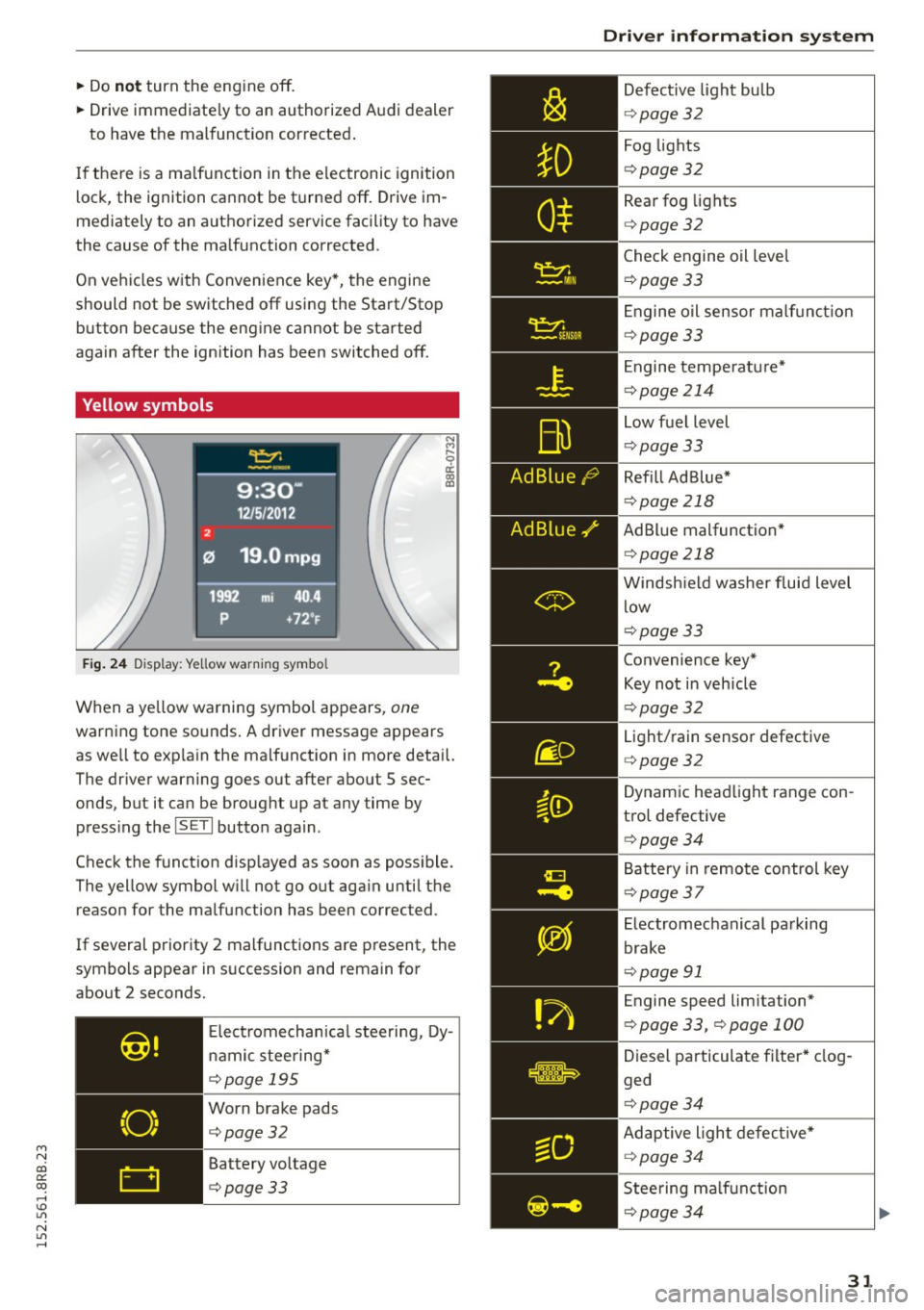
Yellow symbols
Fig. 24 Display: Ye llow warn ing symbo l
N M
9 a: a, a,
When a ye llow warning symbol appears, one
warning tone so unds . A driver message appears
as we ll to exp la in the malf unction in more detail.
The driver warning goes out after about S sec
onds, but it can be brought up at any time by press ing t he
ISETI button again.
Check the function d isp layed as soon as possible.
The yellow symbol w ill not go out aga in until the
reason for the malfunction has been corrected.
If several priority 2 malfunctions are present, the
symbols appear in succession and remain for
about 2 seconds.
Elect rom echan ica l steering, Dy
namic steering*
¢page 195
Worn brake pads
¢page32
Battery voltage
¢page33
Driver information system
Defective light bulb
¢ page 32
Fog lights
¢page 32
Rear fog lights
¢page 32
Check engine oil leve l
¢page 33
Engine oil sensor malf unc tion
¢page 33
Engine temperature*
¢page 214
Low fuel level
¢page 33
Refill Ad Blue*
¢page 218
AdBlue malfunction *
¢page 218
Windshield washer fluid level
low
¢page 33
Convenience key*
Key not in veh icle
¢ page 32
Light/rain sensor defective
¢page 32
Dynamic headlight range con
trol defective
¢ page 34
Battery in remote control key
¢page 37
Electromechanical parking
brake
¢page 91
Engine speed lim itation*
¢ page 33, ¢page 100
Diesel particulate filter* clog
ged
¢ page 34
Adaptive light defective*
¢page 34
Steering malfunction
¢page 34
31
Page 39 of 302
from transmitters in the v icinity of the vehi
cle working in the same frequency range
(e.g . a cell phone, rad io equipment).
- If you open the driver's door with the key
l eft in the ign ition lock, a chime will sound .
This is your reminder to remove the key and
l ock the door.
- For security reasons, replacement keys are
on ly available from Audi dea lers.
- For Declarat ion of Compliance to United
States FCC and Industry Canada regulations
¢page 284.
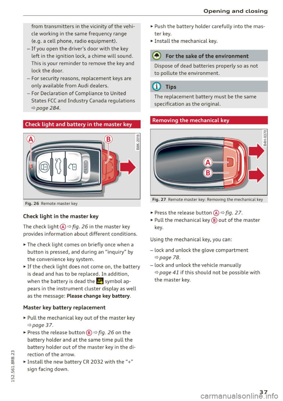
Check light and battery in the master key
F ig . 26 Remote master key
Check light in the maste r key
The check light @¢ fig. 26 in the master key
provides informat ion about different conditions.
.,. The check light comes on b riefly once when a
button is pressed, and dur ing an "inqui ry" by
the conven ience key system.
.,. If the check light does not come on, the battery
is dead and has to be replaced. In addition,
when the battery is dead the
!I symbo l ap
pears in the instrument cluster display as well
as the message:
Please change k ey battery .
Ma ster key b attery repl ace ment
.,. Pull the mechan ica l key out of the master key
¢ page 37 .
.,. Press the release button ®¢ fig. 26 on the
battery holder and at the same time pull the
battery holder out of the master key i n the di-
M
N rect ion of the a rrow. co
~ .,. Install the new battery CR 2032 with the"+"
; s ign fa cing down.
N l/1 ......
Open ing and clo sing
.,. Push the battery holder carefully into the mas
ter key .
.,. Insta ll the mechanical key .
@ For the sake of the en vironment
D ispose of dead batter ies prope rly so as not
to po llute the environment .
@ Tips
The replacement battery must be the same
specification as the origina l.
Removing the mechanical key
Fig . 27 Remote master key: Re mov ing the mechanical key
.,. Press the release b utton @¢ fig. 2 7.
.,. Pull the mechanical key ® out of the master
key.
U sing the mec hanical key, you can:
- lock and unlock the glove compartment
¢page 78.
- lock and unlock the vehicle manually
¢ page 41 if this should not be possible with
th e mast er key.
37
Page 40 of 302
Opening and closing
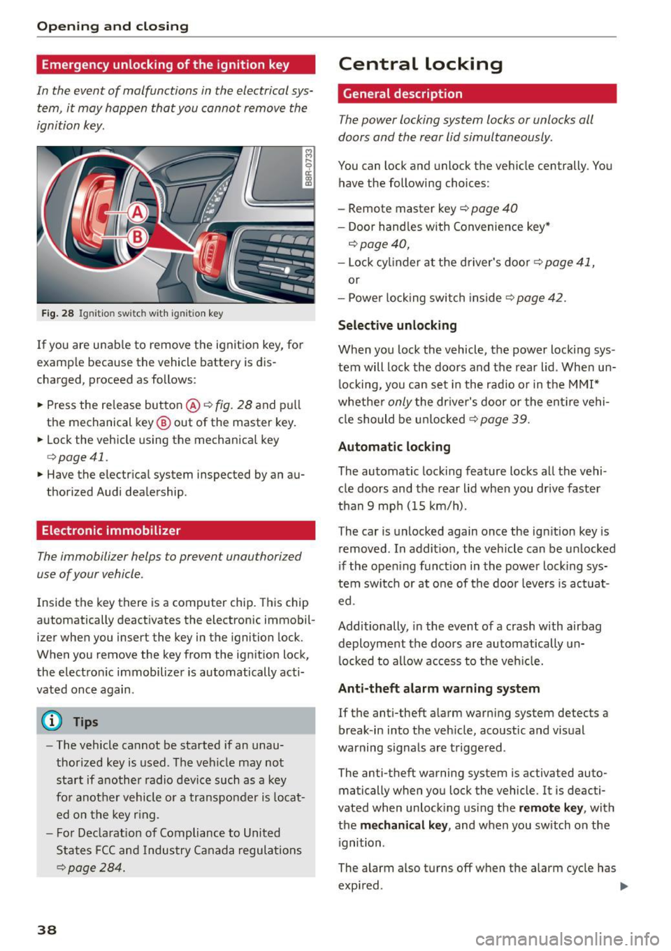
Emergency unlocking of the ignition key
In th e event of malfunctions in the electrical sys
tem, it may happen that you cannot remove the
ignition key.
F ig. 28 Ig nit io n sw it ch w it h ig nition key
If you are unab le to remove the ignition key, for
examp le because the vehicle battery is d is
charged, proceed as follows:
.. Press the re lease button @~
fig. 28 and pull
the mechanical key @ out of the master key .
.. Lock the vehicle using the mechanical key
q poge 41.
.. Have the electr ical system inspected by an au
thorized Audi dealership .
Electronic immobilizer
The immobilizer helps to prevent unauthorized
use of your vehicle .
Inside the key there is a computer chip . This ch ip
automatically deact ivates the electronic immobil
izer when you insert the key in the ignition lock.
When you remove the key from the ig nition lock,
the electro nic immobilizer is automatically acti
vated once again .
(D Tips
-The vehicle cannot be started if an unau
thorized key is used . T he vehicle may no t
start if another radio device such as a key
fo r anot her vehicle o r a transpo nder is locat
ed on the key r ing.
- F or De clarat io n of Compliance to United
States FCC and Indus try Canada regula tio ns
~ page 28 4 .
38
Central locking
General description
The power locking system locks or unlocks oil
doors and the rear lid simultaneously .
You can lock and unlock the ve hicle centrally . You
have the following choices:
- Remote master key
c::> page 40
- Doo r hand les with Convenie nce key *
c::> page 40,
-Lock cy linder at the d river's doo r c::> page 41,
or
- Power lo ck ing swit ch inside
~page 42.
Selective unlocking
When you lock the vehicle, the power locki ng sys
tem will lock the doors and t he rear lid . When un
l ocking, yo u can set in the rad io or in the MMI*
whethe r
only the dr iver's door or the ent ire vehi
cl e should be u nlocked
c::> page 39.
Automatic locking
The automatic locking feature locks all the vehi
cle doors and the rear lid whe n you drive faster
than
9 mp h (15 km/h).
The car is unlocked again once the ig nition key is
removed . In a ddi tion, the vehicle can be un locked
i f the open ing funct ion in th e power lock ing sys
tem swit ch or at o ne of the door leve rs is act uat
ed .
Additionally , in the event of a crash with airbag
deployment the doors a re automatically un
l ocked to a llow access to t he veh icle.
Anti-theft alarm w arning system
If the anti-theft a larm warning system detects a
break -in i nto the veh icle, acoustic and visual
warning signals are t rigge red .
The anti-theft warning system is activated auto ma tically when you lock the vehicle. It is deacti
vated when unloc king us ing the
remote key , with
the
me chanical key , and when you switch on the
i gnition .
The alarm also turns off w hen the alarm cycle has
expi red. ..,.
Page 43 of 302

M N
co ~ co
rl I.O
"' N
"' rl
must be within a range of about 5 feet (1.5 me
ters) from the appropriate door or the rear lid.
It
makes no difference whether the master key is in
your jacket pocke t or in your brief case .
I f you grip the door handle while locking, this can
adversely affect the locking function.
It is not possible to re-open the door for a brief
period direc tly after closing it. This allows yo u to
ens ure that t he doors are properly locked .
WARNING .!!!!!!!!!!.. -
Read and follow a ll WARNINGS ¢ & in Gener-
al description on page 39.
@ Tips
I f your vehicle has been stand ing for an ex
tended period, please note the fol low ing :
- The proxim ity sensors are de act ivated after
a few days to save power. Yo u then have to
pull on the door handle once to unlock the
vehicle and a second time to open the vehi
cle.
- To prevent the battery from being dis
charged and to preserve your veh icle's abili
ty to start for as long as possib le, the ener
gy management system gradually switc hes
off unnecessary convenience functions . It is
possible that you w ill not be able to unloc k
you r vehicle using these convenie nce func
tions.
- Fo r Decla rat ion of Compliance to United
Sta tes FCC and Industry Canada regulations
¢ page 284.
Open ing and clo sing
Operating locks with the mechanical key
In the event of a failure of the power locking sys
tem, the driver's door con locked and unlocked
with the mechanical key at the lock cylinder .
Fig . 31 Key turn s for openin g an d clos ing
To unlock the vehicle
""I nsert the mechan ica l key into the lock o f the
driver's door.
.. Turn the mechanical key to position @
¢fig. 31.
To lock th e vehicle
"" Move the selector lever to the P pos it ion ( auto
matic t ransm ission).
.. Close a ll windows and doors properly.
.. Tur n the mechanica l key in th e lock of the driv
er's door to the lock position
@ ¢A in Gener
al description on page 39.
If the power locking system fails, there is emer
gency locking for the passenger's door and the
rear doors
¢ page 42 .
A WARNING
Read and follow all WAR NINGS ¢ & in Gener
al description on page 39 .
(D Tips
-After the ignition is switched on, the power
locking system sw itch and the unlocking
butto n for the rear lid~ in the door are en
abled.
41
Page 47 of 302
M N
co ~ co
rl I.O
"' N
"' rl
-Always ensure that no one is with in range of
the rear lid when it is mov ing, in particular
close to the hinges and the upper and lower
edges - f ingers or hands can be pinched.
- To help prevent po isonous exhaust gas from
being drawn into the vehicle, a lways keep
the rear lid closed wh ile driving . Never
transport objects large r than those wh ich fit
compl etely into the luggage area , because
then the rea r lid cannot be fully closed .
- Never leav e your vehicle unattended espe
c ially w ith the rear lid left open. A ch ild
c ou ld craw l in to the car through t he luggage
c ompartment and pull the lid s hut, becom
ing t rapped and unable to get ou t. To red uce
the risk of perso nal in jury, never let children
play i n or around your veh icle . Always keep
the rear lid as well as the vehicle doors
closed when not in use.
- If there is a luggage rack or bicycle rack
mounted on the rear lid, it may not be able
to open completely or an ope ned rear lid
may close by itse lf because of the added
we ight. So the open rear lid must be sup
ported or the weight m ust be removed from
the luggage ra ck fi rst .
(O} Tips
- As soon as the electrical connection to the
tra ile r socket is completed on veh icles with
a f actory insta lled towing hitch, o r a trailer
hitch that was insta lled later acco rding to
fac tory spe cifi ca tions , th e au tomat ic rear li d
fu nct ion can only be operate d via the hand le
in the rea r lid .
- If th e vehicle battery charge drops below a
certain level, yo u can sti ll open or close the
r ear lid manua lly, however, you w ill need to
apply more force to close it.
- If the rear lid on a locked vehicle is un locked
with the middle button
,c:$ on the remote
key, the rear lid is automatically locked
again immediately after closing. This is indi
cated by the turn s ignals bli nking.
- The f ollowing applies to veh icles equipped
with the Conve nience key" feature: if the re
mote control key is left in the luggage com
partment, luggage compartment will auto-
Open ing and clo sing
matically unlock itse lf after yo u loc k the ve
hicle. This prevents you from unintentional·
Ly locking yo ur key in the luggage compart
ment.
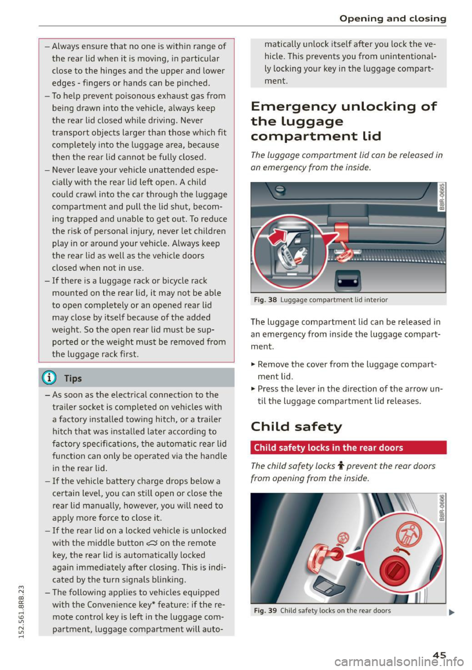
Emergency unlocking of
the luggage compartment Lid
The luggage compartment lid can be released in
an emergency from the inside.
Fi g. 3 8 Luggage co mpa rtment lid i nte rior
T he luggage compartment lid can be released in
an emergency from inside the luggag e compart
me nt.
., Remove the cover from t he luggage compart
ment lid .
., Press the leve r in the di rection of the arrow un
t il the luggage compa rtment lid releases.
Child safety
Child safety locks in the rear doors
The child safety locks t prevent the rear doors
from opening from the inside.
Fig . 39 Chil d safety locks o n th e rea r doo rs
45
Page 49 of 302
M N
co ~ co
rl I.O
"' N
"' rl
Convenience opening/closing
The windows and the Panoramic sliding sunroof*
can be opened and closed with the mechanical
key or the emergency key.
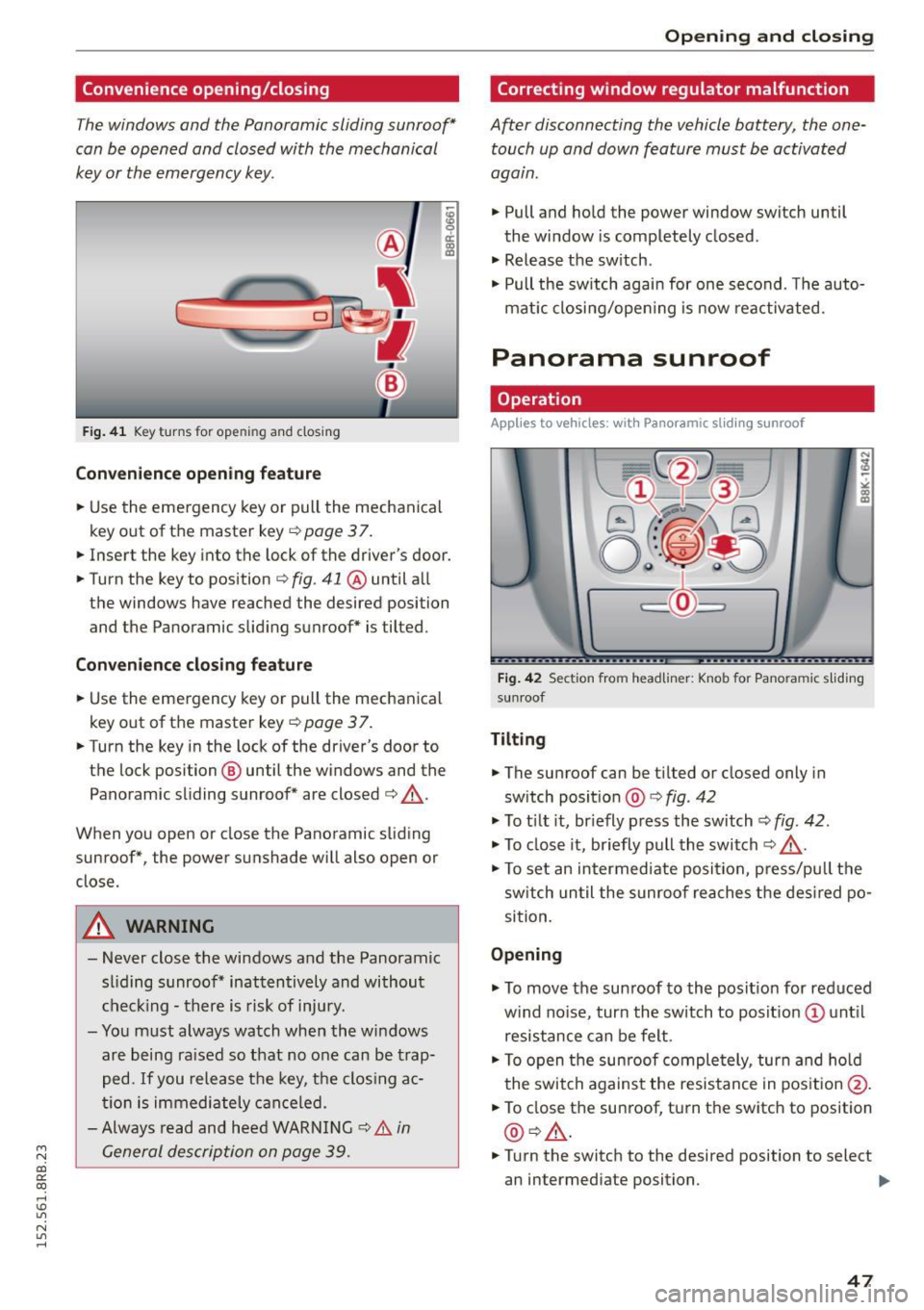
F ig . 41 K ey turns for ope ning and closing
Convenience opening feature
.. Use the emergency key or pull the mechanical
key out of the master key ¢
page 3 7 .
18 9 a::
"' a,
.. Insert the key into the lock of the driver's door .
.. Turn the key to position ¢
fig. 41 @ until a ll
the windows have reached the desired position and the Panoramic slid ing sunroof* is tilted.
Convenience closing feature
.. Use the emergency key or pull the mechanical
key out of the master key
¢ page 37.
.. Turn the key in the lock of the driver's door to
the lock position @ until the windows and the
Panoramic sliding sunroof* are closed ¢ ,&..
When you open or close the Panoramic sliding
sunroof*, the power sunshade will also open or
close.
A WARNING
- Never close the windows and the Panoramic
sl iding sunroof* inattentively and without
checking -there is risk of injury.
- You must always watch when the windows
are being ra ised so that no one can be trap
ped.
If you release the key, th e clos ing ac
tion is immediately canceled.
- Always read and heed WARNING ¢
& in
General description on page 39.
Opening and closing
Correcting window regulator malfunction
After disconnecting the vehicle battery , the one
touch up and down feature must be activated
again .
.. Pull and hold the power window switch until
the window is completely closed .
.. Release the sw itch .
.. Pull the switch again for one second . T he auto
mat ic closing/opening is now reactivated.
Panorama sunroof
Operation
Applies to veh icles: w ith Panoramic sl iding sunroof
Fig. 42 Section fro m headliner : Knob fo r Pano ra m ic s liding
sun roof
Tilting
.. The sunroof can be t ilted or closed only in
sw itch posit ion @ ¢
fig. 42
.. To t ilt it, briefly press the switch
<=;>fig. 42.
.. To close it, briefly pull the switch¢.&. -
.. To set an intermediate posi tion, press/pu ll the
switch until the sunroof reaches the desired po
sition.
Opening
.. To move the sun roof to the position for reduced
w ind no ise, turn the switch to posit ion (!) until
resistance can be felt.
.. To open the sunroof completely, turn and hold
the switch against the resistance in position @.
.. To close the sunroof, turn the switch to position
@ ¢,&. .
.. Turn the switch to the desired position to select
an intermediate position. .,,_
47
Page 101 of 302

Starting the vehicle
Applies to vehicles: with hybrid drive
The vehicle is started and turned off either w ith
the ign ition key
q page 84 or with the
IS TAR T ENGINE STOP I button* ¢page 87 in the
same way as a conventional vehicle .
When starting the vehicle, the need les in the in
strument cluster
move upward br iefly. When the
vehicle enters d rive ready mode, the status mes
sage
hybrid ready appears briefly in the instru
ment cluster display and the needl e in the power
meter points to READY
q page 99.
Depending on the operation mode of the hybr id
system, there are two possib le drive ready modes
after the vehicle has been started:
Drive r eady mode with combustion engine
If the ope rat ing requirements q page 101 for
e lec tric dr ive mode are
not met, the combustion
Power meter overview
Applies to vehicles: with hybrid drive
H ybri d
engine starts the vehicle as usual. You can start
driving as usual.
Drive ready m ode with th e el ectric motor
If the operating requi rements 9 page 101 for
the e lectr ic dr ive mode are met , the combustion
engi ne remains off after starting the vehicle.
(j) Tips
To p reven t the 12 volt batte ry from d ischarg
i ng, never leave t he veh icle parked in the dr ive
ready mode. Remove the key from the igni tion
or press the
! S T AR T ENGINE ST OP I button *.
When leaving the vehicle always take the key
with you.
The power meter shows the hybrid drive condition and the availability of the hybrid system.
F ig. 1 10 Powe r meter overview
An economical dr iv ing and recuperation range is
shown in g reen . A d riving range that is not eco
n omical is shown in o range. In addi tion, the ba t-
"' tery status provides information about the high
N
~ voltage battery charge stat us.
co
rl I.O
"' N
"' rl
@ Fuel eff icient driving with in the
combust ion engine 's pa rtial load
range
@ System limits for electric driving in
the EV mode
@ El ectric dr iving or driv ing with the
combust ion engine (EFFIC IENCY)
99
Page 102 of 302
Hybrid
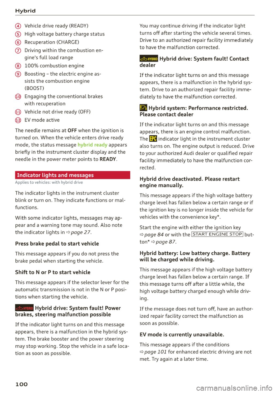
© Vehicle drive ready (READY)
® High voltage battery charge status
® Recuperation (CHARGE)
(f) Driving within the combustion en
gine's full load range
@ 100% combust ion engine
® Boosting -the electric engine as
sists the combustion engine (BOOST)
@ Engaging the convent ional brakes
with recuperation
@ Vehicle not drive ready (OFF)
@ EV mode active
The needle remains at
OFF when the ignition is
turned on. When the vehicle enters drive ready mode, the status message
hybrid ready appears
briefly in the instrument cluster d isplay and the
needle in the power meter points to
READY .
Indicator lights and messages
Applies to vehicles: with hybrid drive
The indicator lights in the instrument cluster
b lin k or tu rn on. They i ndicate functions o r mal
functions.
W ith some ind icator lights, messages may ap
pear and a warning tone may sound. Also note
the indicator l ights in ¢
page 2 7.
Press brake pedal to start vehicle
This message appears if you do not press the
brake pedal when starting the vehicle.
Shift to N or P to start vehicle
This message appears if the selector lever for the
automatic transmission is not in the Nor P posi
tions when starting the vehicle .
-Hybrid drive: System fault! Power
brakes, steering malfunction pos sible
lfthe indicator light turns on and this message
appears, there is a malfunction in the hybrid sys
tem. The brake booster and the power steering
may stop working. Stop the vehicle in a safe loca
tion as soon as possible.
100
You may continue driving if the indicator light
turns off after starting the vehicle severa l times.
Drive to an authorized repair facility immediately
to have the malfunct ion corrected.
Q/ij:@ ,j rlybrid drive: System fault! Contact
dealer
If the indicator light turns on and this message
appears, there is a malfunct ion in the hybr id sys
tem. Drive to an authorized repair facility imme
diately to have the ma lfunction corrected.
Ill Hybrid system : Performance restricted .
Please contact dealer
If the indicator light turns on and this message
appears, there is an engine control malfunction .
The
ffa i ndicator light in the instrument cluster
also t urns on. The eng ine output is red uced . Drive
to you r autho rized Aud i deale r o r qualified repair
facility immediate ly to have the malfunction cor
rected.
Hybrid drive deactivated. Please restart
engine manually.
This message appears if the high volta ge battery
charge level has fallen be low a certain range or if
the ignition key is no longer inside the vehicle fo r
vehicles with the convenience key*.
Start the engine with e ither the ignition key
¢
page 84 or with the !S TAR T EN GINE STOPI but
ton* ¢
page 87.
Hybrid battery: Low battery charge. Battery
will be charged while driving.
This message appears if the high volta ge battery
charge level has fa llen below a certain range. If
this message turns off after a litt le while, the
high voltage battery charged enough w hile driv
i ng .
If the message does not turn off, have an autho r
ized repair facility correct the malfunct ion as
soon as possible.
EV mode is currently unavailable.
This message appears if the cond itions
¢ page 101 for enhanced elect ric driving are not
met. Try again at a later time.
Page 121 of 302

M N
co
a:
co
,...., \!) 1.1'1
N 1.1'1 ,....,
@ Tips
-Side assist is not active wh ile you are mak
i ng the ad justment .
- Your settings are automatically stored and
ass igned to the remote control key being
u sed.
Driver messages
App lies to vehicles: with Audi side assist
If s ide ass ist switches off by itse lf, the LED in the
button turns off and a message wi ll appea r in the
in str ument cluster d is pl ay:
Audi side assist unavailable: Sensors blocked
The radar sensors' vision is affected. Do not cover
the area in front of the senso rs with bike wheels,
sticke rs, dirt or other objects. Clean the area in
fro nt of t he sensors, if necessary
c:> page 117,
fig . 130 .
Audi side assist: Currently unavailable
Side assist cannot be switched o n tempo rari ly be
cause there i s a ma lf u nctio n (for examp le, the
battery c harge level may be too l ow) .
Audi side assist: System fault!
The system cannot guara ntee that it wi ll dete ct
ve hicles co rrectly an d it is switc hed off. The sen
sors have been disp laced or are fau lty. Have t he
system checked by an auth orized A udi dealer or
author ized Audi Serv ice Facility so on .
Audi side ass ist: Unavailable when towing
Side assist sw itches off automatically when a fac
tory- insta lled trailer hitch is connected to the
e lectrica l connector on the tra ile r. The re is n o
g ua rantee the system w ill switch off w hen using
a retr ofitted tra ile r hitch. Do not use s ide assist
wh en towing a tra ile r.
Aud i side assist
119
Page 288 of 302
Index
Automatic driv ing light contro l . . . . . . . . . . . 52
Automatic Sh ift Lock (ASL) . . . . . . . . . . . . . 124
Automatic transmission . . . . . . . . . . . . . . . . 123
Automatic Shift Lock (ASL) . . . . . . . . . . . . 124
Driving ...... .................. ... . 125
Emergency mode . . . . . . . . . . . . . . . . . . . . 127
Emergency release . . . . . . . . . . . . . . . . . . . 128
H ill descent control . . . . . . . . . . . . . . . . . . 126
Kick -down . . . . . . . . . . . . . . . . . . . . . . . . . . 127
Manual sh ift program . . . . . . . . . . . . . . . . 127
Remova l lock (ignition key) . . . . . . . . . . . . . 84
Selector lever . . . . . . . . . . . . . . . . . . . . . . . 123
Shift paddles . . . . . . . . . . . . . . . . . . . . . . . 127
Automatic wipe/wash system . . . . . . . . . . . . 57
Auto Safety Hotline . . . . . . . . . . . . . . . . . . . 142
AUTO (climate control) . . . . . . . . . . . . . . . . . . 81
Average speed . . . . . . . . . . . . . . . . . . . . . . . . . 22
Avoid damaging the vehicle . . . . . . . . . . . . . 199
B
Bass box . . . . . . . . . . . . . . . . . . . . . . . . . . . . 256
Battery . . . . . . . . . . . . . . . . . . . . . . . . . . . . . 230
Battery locat ion inside the luggage compa rt-
ment .............................. 231
Charge level . . . . . . . . . . . . . . . . . . . . . . . . 196
Charging . . . . . . . . . . . . . . . . . . . . . . . 105, 232
Energy management . . . . . . . . . . . . . . . . . 196
Important warnings when working on the
battery . . . . . . . . . . . . . . . . . . . . . . . . . . . . 231
Jump starting . . . . . . . . . . . . . . . . . . . . . . . 271
Replacing the battery . . . . . . . . . . . . . . . . 233
Voltage . . . . . . . . . . . . . . . . . . . . . . . . . . . . . 33
W inte r operation . . . . . . . . . . . . . . . . . . . . 230
Working on the battery . . . . . . . . . . . . . . . 231
Before driving . . . . . . . . . . . . . . . . . . . . . . . . 135
Belt tensioners . . . . . . . . . . . . . . . . . . . . . . . 150
B io-ethanol (Fue l) . . . . . . . . . . . . . . . . . . . . . 214
Blended gasoline . . . . . . . . . . . . . . . . . . . . . 213
Blower (climate control) . . . . . . . . . . . . . . . . . 81
Booster seats . . . . . . . . . . . . . . . . . . . . . . . . 180
Brake fl uid
Changing the brake flu id . . . . . . . . . . . . . . 230
Checking the brake fluid level . . . . . . . . . . 229
Brake system Anti-lock brake system . . . . . . . . . . . . . . . . 17
Brake booster . . . . . . . . . . . . . . . . . . . . . . . 193
286
Brake fluid . . . . . . . . . . . . . . . . . . . . . . . . . 229
Brake fluid specifications for refill and re
placement . . . . . . . . . . . . . . . . . . . . . . . . . 230
Brake light defective . . . . . . . . . . . . . . . . . . 32
Brakes . . . . . . . . . . . . . . . . . . . . . . . . . . . . . 193
E lectromechanical parking brake . . . . . . . . 89
Fluid reservo ir . . . . . . . . . . . . . . . . . . . . . . 229
Malfunction . . . . . . . . . . . . . . . . . . . . . . . . . 28
Wa rning/indicator lights . . . . . . . . . . . . . . . 18
Worn b ra ke pads symbo l . . . . . . . . . . . . . . . 32
Brak ing
Brake assist . . . . . . . . . . . . . . . . . . . . . . . . 191
Braking guard ..... .. .. ... . .... ... 107, 113
Messages . . . . . . . . . . . . . . . . . . . . . . . . . . 114
Settings . . . . . . . . . . . . . . . . . . . . . . . . . . . 114
Switching on and
off . . . . . . . . . . . . . . . . . 114
Break-in period Brake pads . . . . . . . . . . . . . . . . . . . . . . . . . 193
Tires . . . . . . . . . . . . . . . . . . . . . . . . . . . . . . 198
B reak ing in . . . . . . . . . . . . . . . . . . . . . . . . . . 198
New tires . . . . . . . . . . . . . . . . . . . . . . . . . . 242
B reakover angle . . . . . . . . . . . . . . . . . . . . . . 202
Bul bs . . . . . . . . . . . . . . . . . . . . . . . . . . . . . . . 269
C
Californ ia Proposition 65 Warning . . . . . . . 222
Battery specific . . . . . . . . . . . . . . . . . . . . . 232
Capacities . . . . . . . . . . . . . . . . . . . . . . . . . . . 278
AdBlue ... .. .... .. .. .. ........... .. 218
Engine oi l . . . . . . . . . . . . . . . . . . . . . . . . . . 223
Care . . . . . . . . . . . . . . . . . . . . . . . . . . . . . . . . 208
Cargo area
refer to Loading the l uggage compart-
ment..... .. .... .. .. .. ........... .. 140
Cargo floor . . . . . . . . . . . . . . . . . . . . . . . . . . . 71
Catalytic converter . . . . . . . . . . . . . . . . . . . . 198
Center armrest
Adjusting . . . . . . . . . . . . . . . . . . . . . . . . . . . 68
Storage compar tment . . . . . . . . . . . . . . . . . 68
Central locking . . . . . . . . . . . . . . . . . . . . . . . . 38
Certification . . . . . . . . . . . . . . . . . . . . . . . . . 284
Chang ing
Engine oil . . . . . . . . . . . . . . . . . . . . . . . . . . 226
Checking Engine coolant level . . . . . . . . . . . . . . . . . . 227