fuel pressure AUDI Q5 2016 Owners Manual
[x] Cancel search | Manufacturer: AUDI, Model Year: 2016, Model line: Q5, Model: AUDI Q5 2016Pages: 300, PDF Size: 75.02 MB
Page 14 of 300
Instruments and indicator lights
The number of keys programmed to the vehicle is
also displayed. The display
L2 3/3 in dicates that
three keys have been programmed. This a llows
you to make sure you have received all of the keys
when you purchase a used vehicle.
For examp le, if you on ly receive two keys, you
should take those keys to your authorized Audi
dealer to have the missing key deactivated so it
cannot be used. You should also report the miss
ing key to your insurance company .
Calling up the driver information
A yellow or red symbol appears in the instrument
cluster display, usually with a driver message.
The driver message display disappears after
about 5 seconds. The dr iver message can be dis
played again by briefly pressing the
ISETI button.
Setting the speed warning
By pressing the !SET ! button briefly, you can set
thresho ld 1 of the speed warning while you are
driving
c::;, page 95. By maintaining pressure on
the
! SET I button, you delete the warning thresh
old.
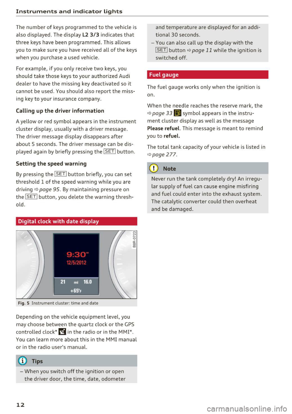
Digital clock with date display
F ig. 5 Instrument cluster: time and date
Depending on the vehicle equipment level, you
may choose between the quartz clock or the GPS
controlled clock*
l!j in the radio or in the MMI*.
You can learn more about th is in the MMI manual
or in the radio user's manual.
@ Tips
- When you switch off the ignition or open
the driver door, the time, date, odometer
12
and temperature are displayed for an addi
tional 30 seconds.
- You can also call up the display with the
!SET ! button c::;, page 11 while the ignition is
switched
off.
Fuel gauge
The fuel gauge works only when the ignition is on.
When the needle reaches the reserve mark, the
c::;, page 33 Ji] symbol appears in the instru
ment cluster display as well as the message
Please refuel. This message is meant to remind
you to
refuel.
The total tank capacity of your veh icle is listed in
c::;, page 2 77.
(D Note
Never run the tank comp letely dry! An irregu
l ar supply of fuel can cause eng ine misfiring
and fuel could enter into the exhaust system.
The catalytic converter cou ld then overheat
and be damaged .
Page 32 of 300
Driver information s ystem
CJ) Note
Do not contin ue driving if the. symbo l ill u
m inates . There is a malfunction in the eng ine
cooling system -you could damage your en
gine.
'l=:;r: Engin e oil pressure malfunction
The red engine oil pressure warning symbol re
quires immedia te service or repair. Driving wi th a
low oil pressure indi cation is likely to cause se
vere engine damage .
If the . symbol on the display flashes, the en
g ine oil pressure is too low . A driver message ap
pears as well to explain the malfunction in more
deta il. The driver warn ing goes ou t afte r about 5
seconds, but it ca n be bro ugh t up at any t ime by
p ressing the
IS ET I but ton again.
Turn off engine! Oil pressure too low
• Stop the veh icle .
• Turn the eng ine off.
• Check the eng ine oi l level
c> page 224.
• Contact your authorized Aud i dealer for ass is -
tance if necessary .
Engine oil level too low
If the engine oil level is too low, add eng ine oil
c>page224.
Engine oil level correct
If the symbo l. flashes even though the engine
oil leve l is correct, p lease contact your nearest
authorized Audi Dealer for assistance. Do not
continue dr iv ing . Do not leave the engine running
idle, either .
(D Tips
- The engine oil pressure symbol. is not
an indicato r for a low engine oil level. Do
not rely on it. Instead, check the oil level in
your engine at regular intervals, preferably each time you refuel, and always before
going on a long trip .
- The yellow oil level warning indication
Ill
requires oil refill or workshop service with
out delay. Do not wait until the red oil
30
pre ssure warning • starts to flash before
you respond to the low oil level warning
II. By then , your engine may already have
suffered serious damage.
~ ... Fill engine oil now
WARNING : Please add oil immediately
If the . symbol lights up, then the oil has to be
r ep lenished right now
c> page 224 .
@-Steer ing malfunction
If there is a malfunction in the electronic steer
ing column lock, the steering cannot be un
locked.
If the . symbo l in t he d isp lay bli nks, the re is a
malfunction in the e lectronic stee ring co lumn
l ock. A driver message appears as well to exp la in
the malfunct ion in more detail. The driver warn
i ng goes out afte r about 5 seconds, but it can be
broug ht up at any time by press ing the
ISET ! but
ton aga in.
Steering defective! Do not drive vehicle!
• Contact your nea rest authorized Audi dealer .
• Do
not tow your veh icle .
A WARNING
Your ve hicle must not be towed in the event
of a malfunction in the electronic steering
column lock because it cannot be steered due
to the loc ked st eering . If i t is towed with the
ste ering locked, t here is t he risk of an a cci
d ent.
© -Ignition lock malfunct ion
A malfunction in the ignition lock must be re
paired immediately.
If the . symbo l in the display b links , there is a
malfunction in the e lectronic ignition lock . A d riv
e r message appears as well to explai n the mal
funct ion in more de tail. The d rive r warning goes
out af ter abou t 5 se co nds, b ut it can be brought
u p at any t ime by pressi ng the
!SE T! b utton ag ain .
Ignition lock defective. Contact dealer! ..,..
Page 103 of 300
,....,
N
co
er::
co
,....,
The combustion engine is operated on ly as need
ed . Gene rally, the combustion engine turns off
when the vehicle is stationary and the high vo lt
age battery powers the electrical vehicle sys
tems.
The purpose of automatica lly shutting the com
bustion engine off in hybrid drive mode is to save
fuel. All of the important vehicle systems, such
as steering, brakes and the A/C system, continue
to rema in active. In some cases, systems may re
qu ire the combustion eng ine to continue running
when the vehicle is stationary . When dr iving in
congested traffic for long periods of t ime, the
combustion engine will cycle on when the veh icle
is stat iona ry to keep the h igh voltage battery
charged.
Gliding
If the gas pedal is not pressed and the D posit ion
is selected, the combustion engine remains
turned off up to speeds of app roximately 99 mph
(160 km/h) . D riving conservat ively like th is can
reduce fuel c:on5umption .
Energy recovery (recuperation )
When braking, the electric motor will act as a
generator creating electr ic energy that is then
sto red in the high voltage battery. This also oc
curs when the ve hicle is coasting or dr iving down
hill. The combustion engine is automatica lly
turned off in this case.
Tips for Driving Efficiently with your Hybrid
A ppl ies to vehicles: with hybr id drive
Driving situa- Conditions
tions
- Shift into the D position .
Starting from a -
Release the brake pedal.
Hybrid
The vehicle is braked with the electric motor by
applying early and even pressure to the brakes
and using short pedal movements~
page 98,
fig. 110 @. By doing this, a large amount of the
kinetic energy is recovered and may be stored as
electric energy in the high voltage battery. Dur
i ng heavy brak ing, the conventional brakes are al
so act ivated
~ page 98, fig . 11 0@ .
The energy recovery is shown in the MMI d isplay
~ page 104 .
Automatic start of the combustion engine
Various operating conditions cause the combus
t ion eng ine to start automatically:
- The high vo ltage battery charge level is low.
- The temperatu re of the combustion engine is
low.
- The temperature of the catalytic converter is
low.
- The power output needed for the A/C system is
high.
- The vehicle speed is high .
- The vehicle acceleration is high .
- The incline is steep .
- High charge level for the high voltage battery
when coasting. In this case, the high voltage battery cannot absorb any more energy and so
the electric motor cannot slow down the veh i
cle . The combust ion engine turns on (engine
brake). In th is situation the high voltage bat
tery will show a Max charge.
Vehicle behavior
In the D posit ion, the hybrid system adapts
to the dr iving situat ion by automatically
stop -
Only press moderately on the ac- switch
ing between the combust ion engine
and e lectr ic dr ive types or by combining
celerator pedal.
them.
101
Page 226 of 300
Checking and Filling
@ Tips
-The oil pressure warning display. is not
an indicator of the oil level. Do not rely on
i t. Instead , check the oil level in your en
gine at regular intervals, preferably each
time you refuel, and always before going
on a long trip.
- If you have the impression your engine con
sumes excessive amounts of oil, we recom
mend that you cons ult an autho rized Aud i
dealer to have the cause of your concern
properly diagnosed . Keep in mind that the
accurate measurement of oil consumption
requires great care and may take some
time. An authorized Audi dealer has instruc
tions about how to measure oil consump
tion accurately.
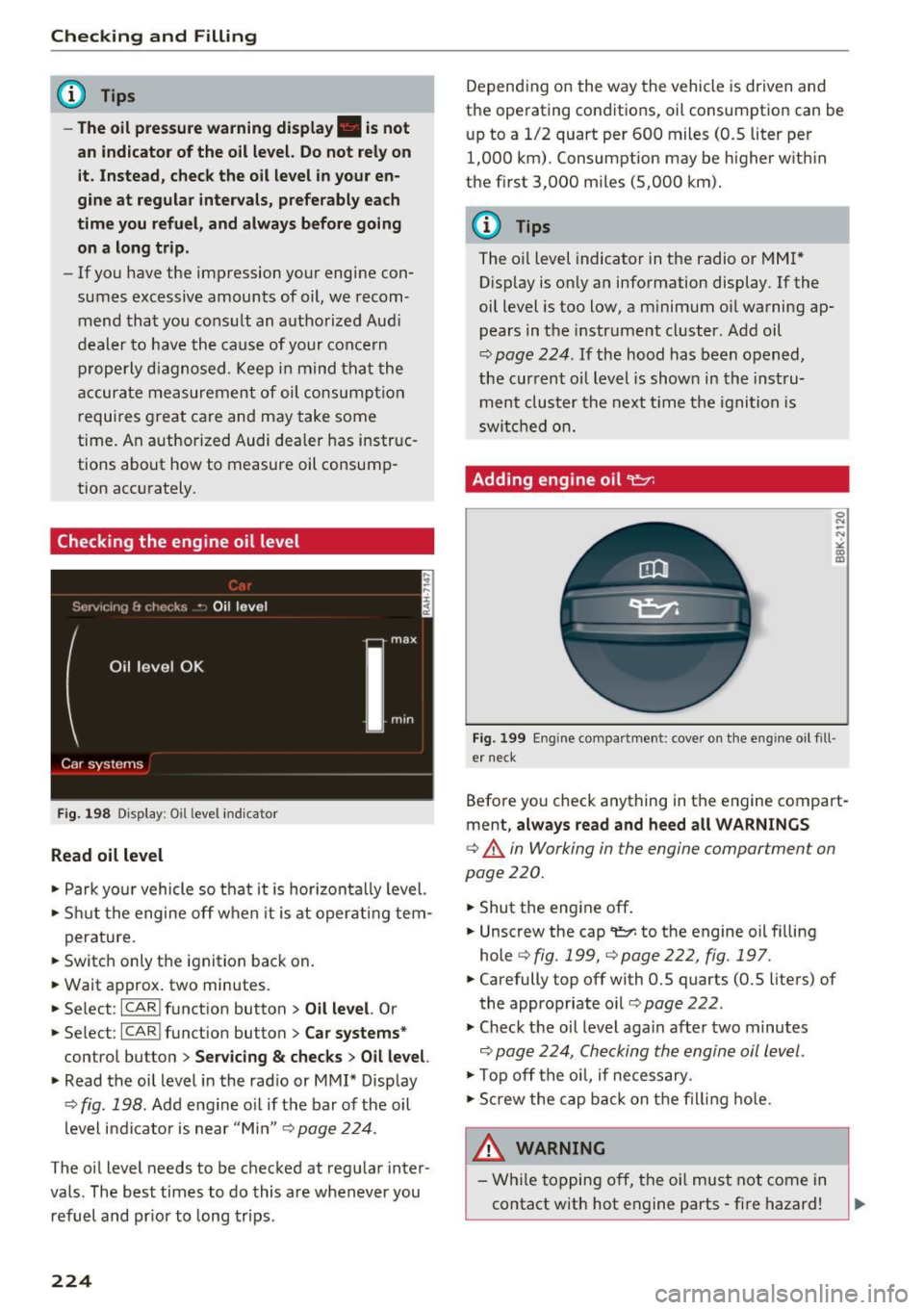
Checking the engine oil level
Fig. 198 D is play: Oil level indicator
Read oil level
• Park yo ur vehicle so that it is hor izonta lly level.
• Shut the engine off when it is at operating tem-
perature.
• Switch only the ignition back on.
• Wait approx . two minutes.
• Se lect:
ICARI function button > Oil level. Or
• Se lect:
ICARI funct ion button> Car systems *
control button > Servicing & checks > Oil level.
• Read the oil level in the radio or MMI* Display
¢
fig. 198. Add engine o il if the bar of the oil
level indicator is near "Min"
Q page 224.
The oil level needs to be checked at regular inter
vals. The best times to do this are whenever you refuel and pr ior to long trips .
224
Depending on the way the vehicle is driven and
the operating conditions, oil consumption can be
up to a 1/2 quart per 600 miles (0.5 liter per
1,000 km). Consumption may be higher w it hin
the first 3,000 miles (5,000 km).
(D Tips
The o il level indicator in the radio or MMI*
D isp lay is only an information display. If the
oil level is too low, a m inimum oil warning ap
pears in the instrument cluster. Add oil
¢
page 224. If the hood has been opened,
the current oil level is show n in the instru
ment cluster the next time the ignition is
switched on.
Adding engine oil
er neck
Before yo u check anything in the engine compart
ment,
always read and heed all WARNINGS
¢ .&. in Working in the engine compartment on
page 220.
• Shut the engine off.
• Unscrew the cap
't=r. to the engine oil f illing
hole ¢
fig. 199, ¢ page 222, fig. 197.
• Carefully top off with 0.5 quarts (0.5 liters) of
the appropriate oil¢
page 222.
• Check the oil level again after two minutes
Q page 224, Checking the engine oil level.
• Top off the oil, if necessary .
• Scr ew the cap back on the filling hole.
& WARNING
- While topping off, the oil must not come in
contact with hot engine parts - fire hazard!
Page 239 of 300
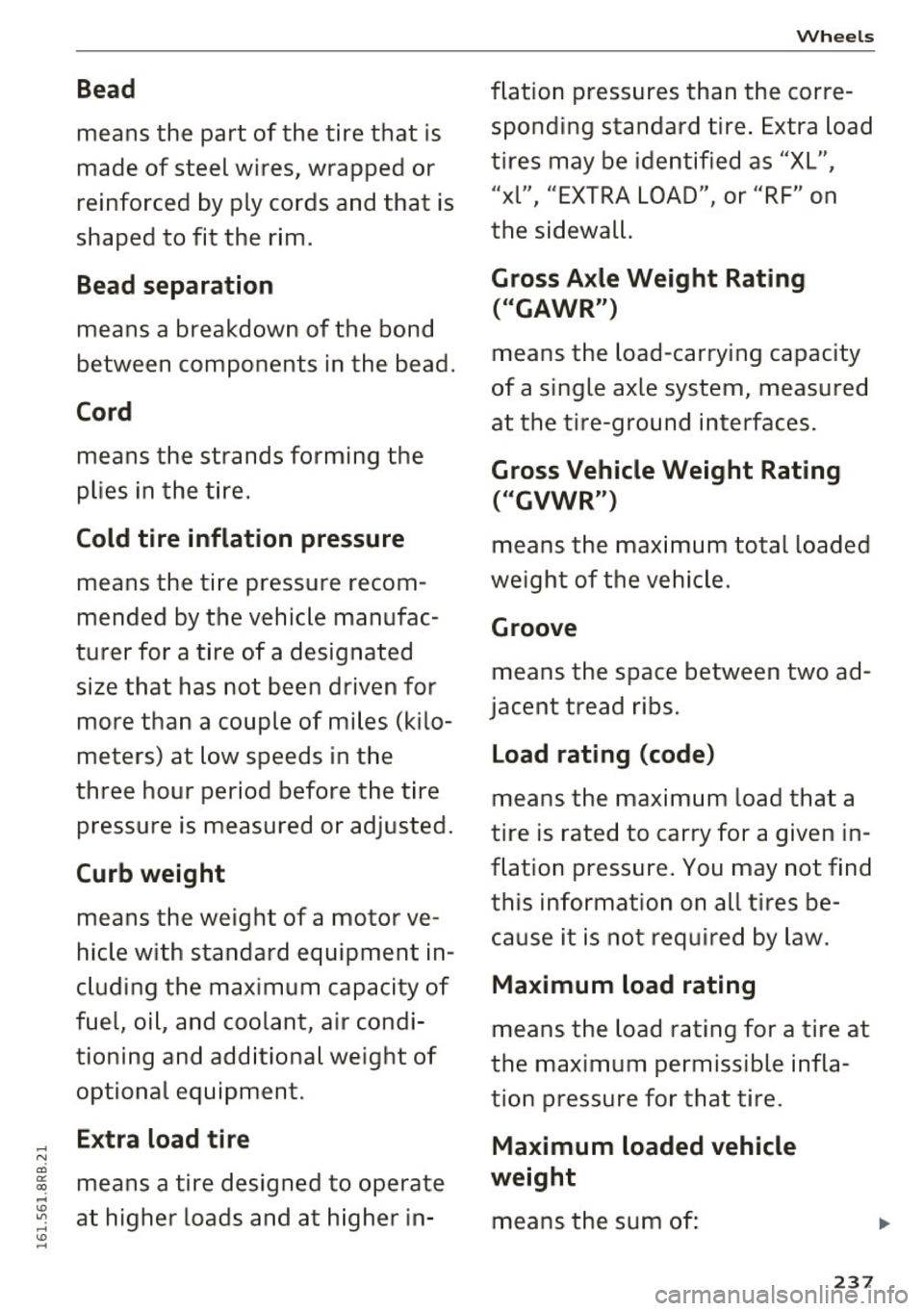
Bead
means the part of the tire that is
made of steel wires, wrapped or
reinforced by ply cords and that is
shaped to fit the rim.
Bead separation
means a breakdown of the bond
between components in the bead.
Cord
means the strands forming the
plies in the tire.
Cold tire inflation pressure
means the tir e pressure recom
mended by the vehic le manufac
turer for a tire of a designated
size that has not been driven for
more than a couple of miles (kilo
meters) at low speeds in the
three hour period before the tire pressure is measured or adjusted .
Curb weight
means the weight of a motor ve
hicle with standard equipment in
c luding the maximum capacity of
fuel, oi l, and coolant, a ir condi
tioning and add itional weight of
optional equipment.
E xtra load ti re
means a tire designed to operate
at higher loads and at h igher in -
Wheels
flation pressures than the corre
sponding standard tire . Extra load
tires may be identified as "XL",
" xl", "EXTRA LOAD", o r "RF" on
the sidewal l.
Gross Axle Weight Rating
( " GAWR")
means the load -carrying capacity
of a single axle system, measured
at the tire-ground interfaces .
Gross Vehicle Weight Rating
("GVWR ")
means the max imum total loaded
weight of the vehic le.
Groove
means the space between two ad
jacent tr ead ribs .
Load rating (code)
means the max im um load tha t a
tire is rated to carry fo r a g iven in
flat ion pressure . You may not find
this informat ion on all tires be
cause it is not requ ired by law.
Maximum load rating
means the load rating for a tire at
the maximum pe rmissible infla
tion pressure for that tire.
Maximum loaded vehicle
weight
means the sum o f:
23 7
..
Page 247 of 300
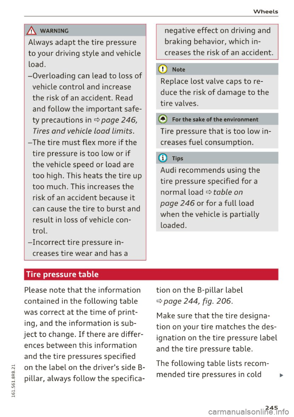
A WARNING
Always adapt the tire pressure
to your driving style and vehicle load.
-Overloading can lead to loss of
vehicle control and increase the risk of an accident. Read
and follow the important safe
ty precautions in¢
page 246,
Tires and vehicle load limits.
-The tire must flex more if the
tire pressure is too low or if
the vehicle speed or load are
too high. This heats the tire up
too much. This increases the risk of an accident because it
can cause the tire to burst and result in loss of vehicle con
trol.
-Incorrect tire pressure in creases tire wear and has a
Tire pressure table
Please note that the information
contained in the following table
was correct at the time of print
ing, and the information is sub
ject to change. If there are differ
ences between this information
and the tire pressures specified
on the label on the driver's side B pillar, always follow the specifica-
Wheels
negative effect on driving and
braking behavior, which in
creases the risk of an accident.
Replace lost valve caps to re
duce the risk of damage to the
tire valves.
@ For the sake of the environment
Tire pressure that is too low in
creases fuel consumption.
(1) Tips
Audi recommends using the
tire pressure specified for a normal load ¢
table on
page 246
or for a full load
when the vehicle is partially
loaded.
tion on the B-pillar label
¢ page 244, fig. 206.
Make sure that the tire designa
tion on your tire matches the des ignation on the tire pressure label
and the tire pressure table.
The following table lists recom mended tire pressures in cold
245
Page 248 of 300
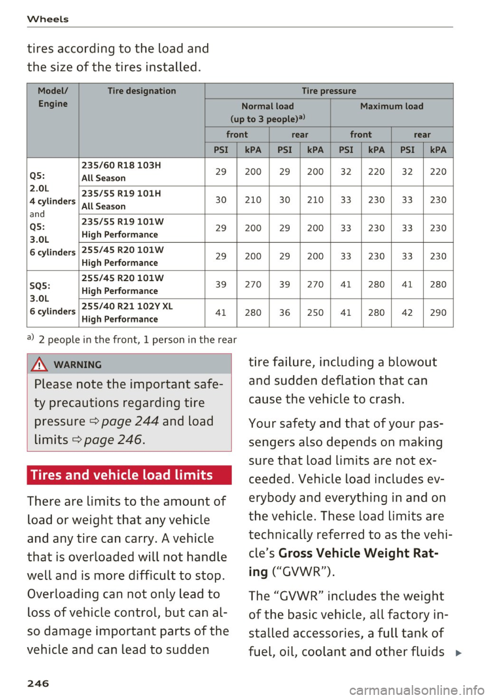
Wheels
tires according to the load and
the size of the tires installed.
Model/ Tire designation
Engine Tire pressure
Normal load Maximum load
(up to 3 people)al
front rear front rear
PSI
235/60 Rl8 103H
29 Q5:
All Season
2 .0L
235/55 R19 101H
4 cylinders All Season
30
and
Q5: 235/55 R19101W 29 High Performance
3.0L
6 cylinders 255/45
R20 101W
29 High Performance
255/45 R20 101W
39 SQ5: High Performance
3.0L
6 cylinders 255/40
R21102Y XL
41 High Performance
a) 2 people in the front, 1 person in the rear
A WARNING
Please note the important safe
ty precautions regarding tire pressure ¢
page 244 and load
limits ¢
page 246.
Tires and vehicle load limits
There are limits to the amount of
load or weight that any vehicle
and any tire can carry. A vehicle
that is overloaded will not handle
well and is more difficult to stop.
Overloading can not only lead to
loss of vehicle control, but can al
so damage important parts of the
vehicle and can lead to sudden
246
kPA PSI kPA PSI kPA PSI kPA
200 29 200 32 220 32 220
210
30 210 33 230 33 230
2 00 29 2 00 33 2 30 33 230
200 29 200 33 230 33 230
27 0
39 27
0 41 2 80 41 2 80
280 36 250 4 1 280 42 290
tire failure, including a blowout
and sudden deflation that can
cause the vehicle to crash.
Your safety and that of your pas
sengers also depends on making
sure that load limits are not ex
ceeded. Vehicle load includes ev
erybody and everything in and on
the vehicle. These load limits are
technically referred to as the vehi
cle's
Gross Vehicle Weight Rat
ing
("GVWR").
The "GVWR" includes the weight
of the basic vehicle, all factory in
stalled accessories, a full tank of
fuel, oil, coolant and other fluids ..,.
Page 254 of 300
Wheels
check your tires as soon as possible, and inflate
them to the proper pressure. Driving on a signifi
cantly under-inflated tire causes the tire to overheat and can lead to tire failure. Under-inflation
also reduces fuel efficiency and tire tread life,
and may affect the vehicle's handling and stop
ping ability.
Please note that the TPMS is not a substitute for
proper tire maintenance, and it is the driver's re
sponsibility to maintain correct tire pressure,
even if under-inflation has not reached the level
to trigger illumination of the TPMS low tire pres
sure telltale.
Your vehicle has also been equipped with a TPMS malfunction indicator to indicate when the sys
tem is not operating properly. The TPMS mal
function indicator is combined with the low tire pressure telltale. When the system detects a
malfunction, the telltale will flash for approxi
mately one minute and then remain continuously
illuminated. This sequence will continue upon
subsequent vehicle start-ups as long as the mal
function exists .
When the malfunction indicator is illuminated,
the system may not be able to detect or signal low tire pressure as intended . TPMS malfunctions
may occur for a variety of reasons, including the
installation of replacement or alternate tires or
wheels on the vehicle that prevent the TPMS from functioning properly . Always check the
TPMS malfunction telltale after replacing one or
more tires or wheels on your vehicle to ensure
that the replacement or alternate tires and
wheels allow the TPMS to continue to function
properly.
252
· If the Tire Pressure Monitoring System
indicator appears
Applies to vehicles: with tire pressure monitoring system
The tire pressure indicator in the instrument
cluster informs you if the tire pressure is too low
or if there is a system malfunction.
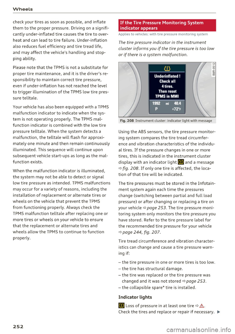
Fig. 208 Instrument cl uster: i ndic ator ligh t with message
Using the ABS sensors, the tire pressure monitor
ing system compares the tire tread circumfer
ence and vibration characteristics of the individu
al tires . If the pressure changes in one or more
tires , this is indicated in the instrument cluster
display with an indicator light
RE and a message
c>fig. 208. If only one tire is affected, the loca
tion of that tire will be indicated.
The tire pressures must be stored in the Infotain
ment system again each time the pressures
change (switching between partial and full load
pressure) or after changing or replacing a tire on
your vehicle
c> page 253. The tire pressure moni
toring system only monitors the tire pressure you have stored. Refer to the tire pressure label for
the recommended tire pressure for your vehicle
c> page 244, fig . 207.
Tire tread circumference and vibration character
istics can change and cause a tire pressure warn
ing if:
- the tire pressure in one or more tires is too low.
- the tire has structural damage.
- the tire was replaced or the tire pressure was
changed and it was not stored
c> page 253 .
-the collapsible spare* tire is installed.
Indicator lights
RE Loss of pressure in at least one tire c> &.
Check the tires and replace or repair if necessary . .,.
Page 268 of 300
Fuses and bulbs
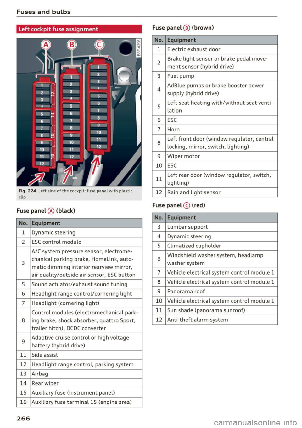
Left cockpit fuse assignment
Fig. 224 Left side of the cockp it: fuse panel with p lastic
clip
Fuse panel @ (black)
No . Equipment
1 Dynamic steering
2 ESC control module
A/C system pressure sensor, electrome-
3 chanical parking
brake, Homelink, auto-
matic dimming interior rearview mirror,
air quality/outside air sensor, ESC button
s Sound actuator/exhaust sound tuning
6 Headlight range control/corner ing light
7 Headlight (cornering light)
Control modules (electromechanical park-
8 ing brake, shock absorber, quattro Sport,
trailer hitch), DCDC converter
9
Adaptive cruise control or high voltage
battery (hybrid dr ive)
11 Side assist
12 Headlight range control, parking system
13 Airbag
14 Rear wiper
15 Auxiliary
fuse (instrument panel)
16 Auxiliary fuse te rm inal 15 (engine area)
266
Fuse panel ® (brown)
No. Equipment
1 Electric exhaust door
2 Brake
light sensor or brake pedal move-
ment sensor (hybrid drive)
3 Fuel pump
4 Ad
Blue pumps or brake booster power
supply (hybrid dr ive)
s
Left seat heating with/without seat venti-
lation
6 ESC
7 Horn
8
Left front doo r (window regulator, central
locking, mirror, switch, lighting)
9 Wiper motor
10 ESC
11 L
eft rear doo r (window regulator, switch,
li ght ing)
12 Rain and light sensor
Fuse panel
© (red)
No. Equipment
3 Lumbar support
4 Dynamic steering
5 Climatized cupholder
6 Windshie
ld washer system, headlamp
washer system
7 Vehicle electrical system control module 1
8 Vehicle electrical system control module 1
9 Panorama roof
10 Vehicle electrical system control module 1
11 Sun shade (panorama sunroof)
12 Anti-theft alarm system
Page 290 of 300
Index
Electronic Stabilization Control . . . . . . . . . . 190
Electronic Stabilization Control (ESC)
Hill descent assist . . . . . . . . . . . . . . . . . . .
192
Offroad mode . . . . . . . . . . . . . . . . . . . . . . . 191
Warning/indicator lights . . . . . . . . . . . . . . . 15
Emergency braking . . . . . . . . . . . . . . . . . . . . . 91
Emergency flasher . . . . . . . . . . . . . . . . . . . . . 54
Warning/indicator lights . . . . . . . . . . . . . . . 16
Emergency key . . . . . . . . . . . . . . . . . . . . . . . . 36
Starting engine . . . . . . . . . . . . . . . . . . . . . . 86
Emergency locking of the doors . . . . . . . . . . . 42
Emergency operation
Luggage compartment lid . . . . . . . . . . . . . .
45
Emergency release
Selecto r lever . . . . . . . . . . . . . . . . . . . . . . .
127
Emergency starting . . . . . . . . . . . . . . . . . . . 270
Emergency unlocking
Ignition key . . . . . . . . . . . . . . . . . . . . . . . . .
38
Energy management . . . . . . . . . . . . . . . . . . 195
Engine
Compartment . . . . . . . . . . . . . . . . . . . . . . .
222
Coolant . . . . . . . . . . . . . . . . . . . . . . . . . . . . 226
H ood . . . . . . . . . . . . . . . . . . . . . . . . . . . . . . 220
Jump starting . . . . . . . . . . . . . . . . . . . . . . . 104
Starting ... .... ............... 84, 87, 98
Starting with jumper cables . . . . . . . . . . . 270
Stopping . . . . . . . . . . . . . . . . . . . . . . 86, 88, 98
Engine compartment . . . . . . . . . . . . . . . . . . 222
Safety instructions . . . . . . . . . . . . . . . . . . . 220
Working the engine compartment . . . . . . 220
Engine coolant system . . . . . . . . . . . . . . . . . 226
Adding coolant . . . . . . . . . . . . . . . . . . . . . . 227
Checking coolant level . . . . . . . . . . . . . . . . 226
Malfunction . . . . . . . . . . . . . . . . . . . . . . . . . 29
Radiator fan . . . . . . . . . . . . . . . . . . . . . . . . 228
Engine coolant temperature
Temperature gauge . . . . . . . . . . . . . . . . . . .
10
Engine hood
Closing . . . . . . . . . . . . . . . . . . . . . . . . . . . .
220
How to release the hood . . . . . . . . . . . . . . 220
Engine oil . . . . . . . . . . . . . . . . . . . . . . . . . . . 222
Adding .. .. .. .. ............. .... .. . 224
Additives . . . . . . . . . . . . . . . . . . . . . . . . . . . 224
Changing . . . . . . . . . . . . . . . . . . . . . . . . . . 225
Check oil level . . . . . . . . . . . . . . . . . . . . . . 224
Consumption . . . . . . . . . . . . . . . . . . . . . . . 224
Level . . . . . . . . . . . . . . . . . . . . . . . . . . . . . . . 33
288 Oil consumption .
. . . . . . . . . . . . . . . . . . . .
223
Pressure malfunction . . . . . . . . . . . . . . . . . 30
Sensor defective . . . . . . . . . . . . . . . . . . . . . . 33
Specification and viscosity . . . . . . . . . . . . . 222
Engine speed limitation . . . . . . . . . . . . . . . . . 33
Env ironment
Catalytic converter . . . . . . . . . . . . . . . . . . .
197
Diesel particulate fi lter . . . . . . . . . . . . . . . 198
Dispos ing of your veh icle battery . . . . . . . 232
Driving at high speeds . . . . . . . . . . . . . . . . 199
Fuel......... ... .. .. ............... 215
Leaks under your vehicle . . . . . . . . . . . . . . 220
Letting the vehicle stand and warm up... 199
Proper disposa l of drained brake fluid . . . 229
Proper disposal of drained engine coolant 227
Proper disposal of drained engine oil 224, 225
Recycling used engine oil . . . . . . . . . . . . . 224
Roof rack . . . . . . . . . . . . . . . . . . . . . . . . . . . 7 4
Unleaded fuel.. .. .. .. ... .......... ..
212
What shou ld I do with an old battery? 232
EPC
refer to Electronic power control
ESC
refer to E lectronic Stabilization
15
Control (ESC) . . . . . . . . . . . . . . . . . . . . . . . . 15
Ethyl alcohol (Fuel) . . . . . . . . . . . . . . . . . . . . 213
Event Data Recorder (EDR) . . . . . . . . . . . . . 189
Expansion tank . . . . . . . . . . . . . . . . . . . . . . . 226
Explanation of some technical terms . . . . . 201
Exterior lighting . . . . . . . . . . . . . . . . . . . . . . . 52
Exterior mirrors
Adjusting . . . . . . . . . . . . . . . . . . . . . . . . . . .
59
D . . 1mming ...... .. .. .. ............. ... 60
Heating . . . . . . . . . . . . . . . . . . . . . . . . . . . . . 59
Eyeglasses compartment . . . . . . . . . . . . . . . . 78
F
Fall line
Fan
Radiator
Fastening 201
228
Booster seats . . . . . . . . . . . . . . . . . . . . . . . 179
Convertible child safety seats . . . . . . . . . . 177
Infant seats . . . . . . . . . . . . . . . . . . . . . . . . 176
Flexible fuel . . . . . . . . . . . . . . . . . . . . . . . . . 213
Floor mats . . . . . . . . . . . . . . . . . . . . . . . . . . . 139