transmission oil AUDI Q5 2018 Owners Manual
[x] Cancel search | Manufacturer: AUDI, Model Year: 2018, Model line: Q5, Model: AUDI Q5 2018Pages: 392, PDF Size: 60.56 MB
Page 22 of 392
Cockpit overv ie w
.....
,,.I...
TPMS
20
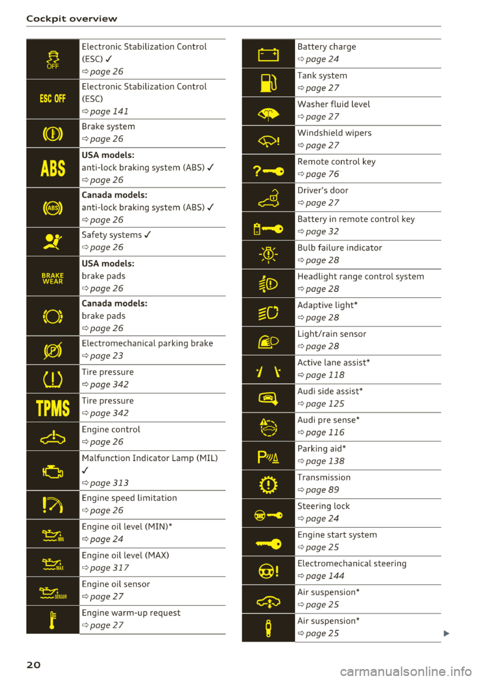
Elect ronic Stabilization Cont rol
( E SC)
./
¢ page 26
Electronic Stabilization Control
( E SC)
¢ page 141
Brake system
¢page26
USA model s:
anti-lock braking system (ABS) ./
¢page26
Canada models :
anti-loc k bra king system (ABS)./
¢ page26
Safety systems./
¢page26
USA models :
brake pads
¢page26
Canada models :
brake pads
¢page26
Elect romechan ica l parking brake
¢ page23
Tire pressure
¢ page342
Tire pressure
¢ page342
Engine control
¢page26
Malfunction Indicator Lamp (MIL)
./
¢page313
Eng ine speed limi ta ti on
¢ page26
Eng ine oil level (MIN)*
¢ page24
Eng ine oil level (MAX)
¢ page 317
Eng ine oil sensor
¢ page27
Engine warm-up request
¢page27
Battery charge
¢page24
Tank system
¢ page 27
Washer fluid level
¢page 27
Windshie ld wipers
¢ page 27
Remo te control key
¢ page 76
Drive r's doo r
¢page 27
Battery i n remote control key
¢ page 32
Bu lb fai lure indicator
¢ page28
Head light range control system
¢ page 28
Adaptive light*
¢page28
Light/rain sensor
¢page 28
Active lane assist*
¢page 118
Audi s ide ass ist*
¢ page 12 5
Audi pre sense *
¢page 11 6
Parking aid*
¢page 138
Transmission
¢ page 89
Steering lock
¢page 24
Engine start system
¢ page 25
Electromechanical steering
¢ page 144
Air suspension*
¢page 25
Air s uspension*
¢ page 25
Page 31 of 392
u co ..... N ,..._
N ..... 0 <( 0 00
The transmission temperature has increased s ig
nificant ly due to the sporty driving manner. Drive
in a less sporty manner until the temperature re
turns to the normal range and the indicator light
switches of .
A WARNING
Contact an authorized Audi dealer or author
ized Aud i Serv ice Facility if the all whee l dr ive/
sport diffe rential is fa ulty o r malfunctioning .
The repair must be performed by trained per
sonnel using the correct oil in or der to ensure
safety .
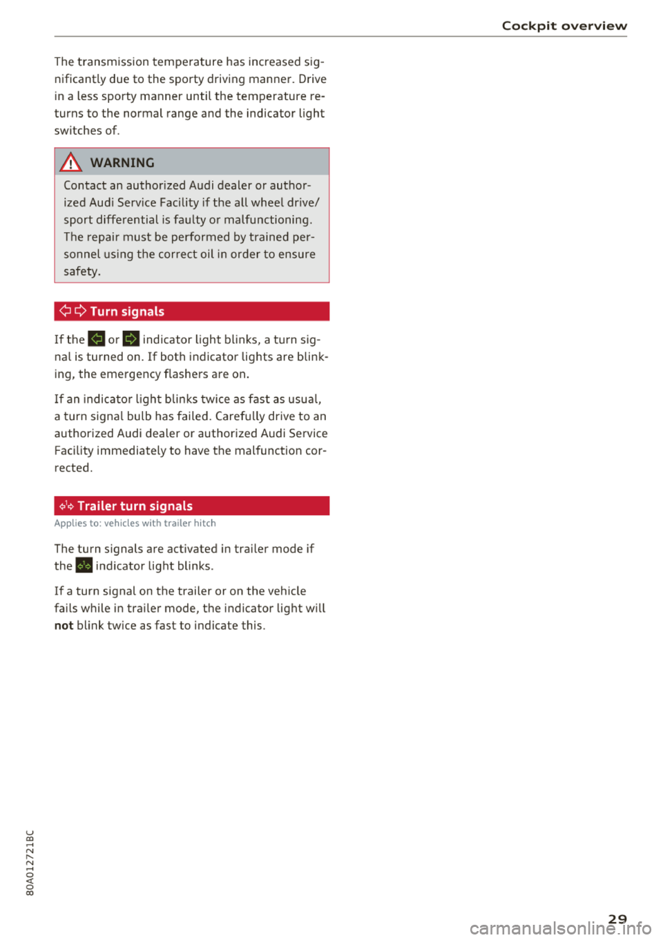
¢¢Turn signals
If the B or II indicator light b links, a t urn sig
na l is turned on. If both indicator lig hts are blink
ing, the eme rgency flashe rs a re on .
I f an indica to r li ght bli nks twice as fast as usu al,
a tu rn signa l bulb has failed . Caref ully drive to an
authorized Audi dealer or authorized Audi Service Facility immediately to have t he mal function cor
rected.
¢19 Trailer turn signals
Appl ies to : ve hicl es w ith traile r hitch
The turn s ignals are activated in tra iler mode if
the . in d icator lig ht blinks .
I f a turn signal on the trailer or on the veh icle
fa ils w hile in tra ile r mode, the indicator light w ill
not blink twice as fast to indicate this .
Cockpit o ver view
29
Page 75 of 392
u co ..... N r--N ..... 0 <( 0 00
Driving
General information
Breaking in
A new vehicle must be broken in for the first
1,000 miles (1,500 km). Do not drive at speeds
that will exceed 2/3 of the maximum permitted
engine speed (RPM) for the first 600 miles
(1,000 km), and avoid full acceleration during
this period . You may gradually start increasing
the RPM and the speed between 600 miles
(1,000 km) and 1,000 miles (1,500 km) .
During the first hours of use, the engine has a
higher internal friction than later on when all
moving parts have settled into p lace with each
other.
How the vehicle is driven during the first 1,000
miles (1,500 km) also affects the engine quality .
Drive at moderate engine speeds after the initial
break-in per iod, part icu larly when running a cold
engine. This will reduce engine wear and improve
the m ileage .
Do not drive at too low of an engine speed (RPM).
Shift down if the engine stops running "smooth ly". Extremely high eng ine speeds are automati
cally reduced.
Reducing the risk of vehicle damage
@ Note
When driving on poor roads, by curbs and on
steep ramps, make sure that low-hang ing
components such as the spoiler and ex haust
system do not come into contact with these
or they cou ld be damaged. This especia lly ap
plies to vehicles with low ground clearance
and veh icles that are heavily loaded.
Driving through water on roads
Note the following to reduce the r isk of vehicle
damage when driv ing through water, for example
on flooded roads:
- The water must not be any higher than the bot
tom of the vehicle body .
Driving
-Do not drive faster than walking speed.
A WARNING
= -
After driving thro ugh water or m ud, the effec
tiveness of the brakes may be reduced due to
moisture on the brake rotors and brake pads.
A few careful brake applications shou ld dry
off the brakes and restore the fu ll braking ef
fect.
@ Note
- Vehicle components such as the engine, transmission, suspens ion or electrical sys-
tem can be severely damaged by driving
through water.
- Always switch the Start/Stop system* off
when driving through water
¢page 78.
(D Tips
-Determine the depth before driving through
water.
- Do not stop the vehicle, drive in reverse or
switch the engine off when driving through
water.
- Keep in mind that oncom ing vehicles may
create waves that raise the water level and
make it too deep for your vehicle to drive
through safely.
- Avoid dr iv in g through salt water, because
this can cause corrosion.
Economical and environmentally-friendly
driving
T he amount of fuel consumption, the environ
menta l impact and the wear to the engine,
brakes and tires depends most ly on your driving
sty le. With an anticipatory and economic driving
style, fuel consumption can be reduced by ap prox imately 10-15%. The following t ips will help
you conserve the environment and your money at the same time .
Anticipatory driving
A vehicle uses the most fuel when accelerating.
When you drive w ith anticipation, you do not
need to brake as often and so you accelerate less.
When poss ible, let your vehicle coast with a gear
.,.
73
Page 330 of 392
Wheel s
Glossary of tire and loading
terminology
Accessory weight
means the combined weight (in
excess of those standard items
which may be replaced) of auto matic transmission, power steer
ing , power brakes , power win
dows , power seats, radio, and
heater, to the extent that these
items are available as factory-in
stalled equipment (whether in
stalled or not).
Aspect ratio
means the ratio of the height to
the width of the tire in percent. Numbers of 55 or lower indicate a
low sidewall for improved steer
ing response and better overall
handling on dry pavement .
Bead
means the part of the tire that is
made of steel wires, wrapped or
reinforced by ply cords and that is
shaped to fit the rim.
Bead separation
means a breakdown of the bond
between components in the bead.
328
Cord
means the strands forming the
plies in the tire.
Cold tire inflation pressure
means the t ire pressure recom
mended by the vehicle manufac
turer for a tire of a designated
size that has not been driven for
more than a couple of miles (kilo
meters) at low speeds in the
three hour period before the tire pressure is measured or adjusted.
Curb weight
means the weight of a motor ve
hicle w ith standard equipment in
cluding the maximum capacity of
fuel, oil, and coolant, ai r condi
tioning and additional weight of
optional equipment.
E x tra load ti re
means a tire designed to operate
at higher loads and at higher in
flation pressures than the corre
sponding standard tire. Extra load
tires may be identified as "X L",
"
l" "EXTRA LOAD" or "RF" on X I I
the sidewall. .,.
Page 369 of 392
u co ..... N r-N .....
~ 0 co
Raising the vehicle
Lifting with workshop hoist and with floor
jack
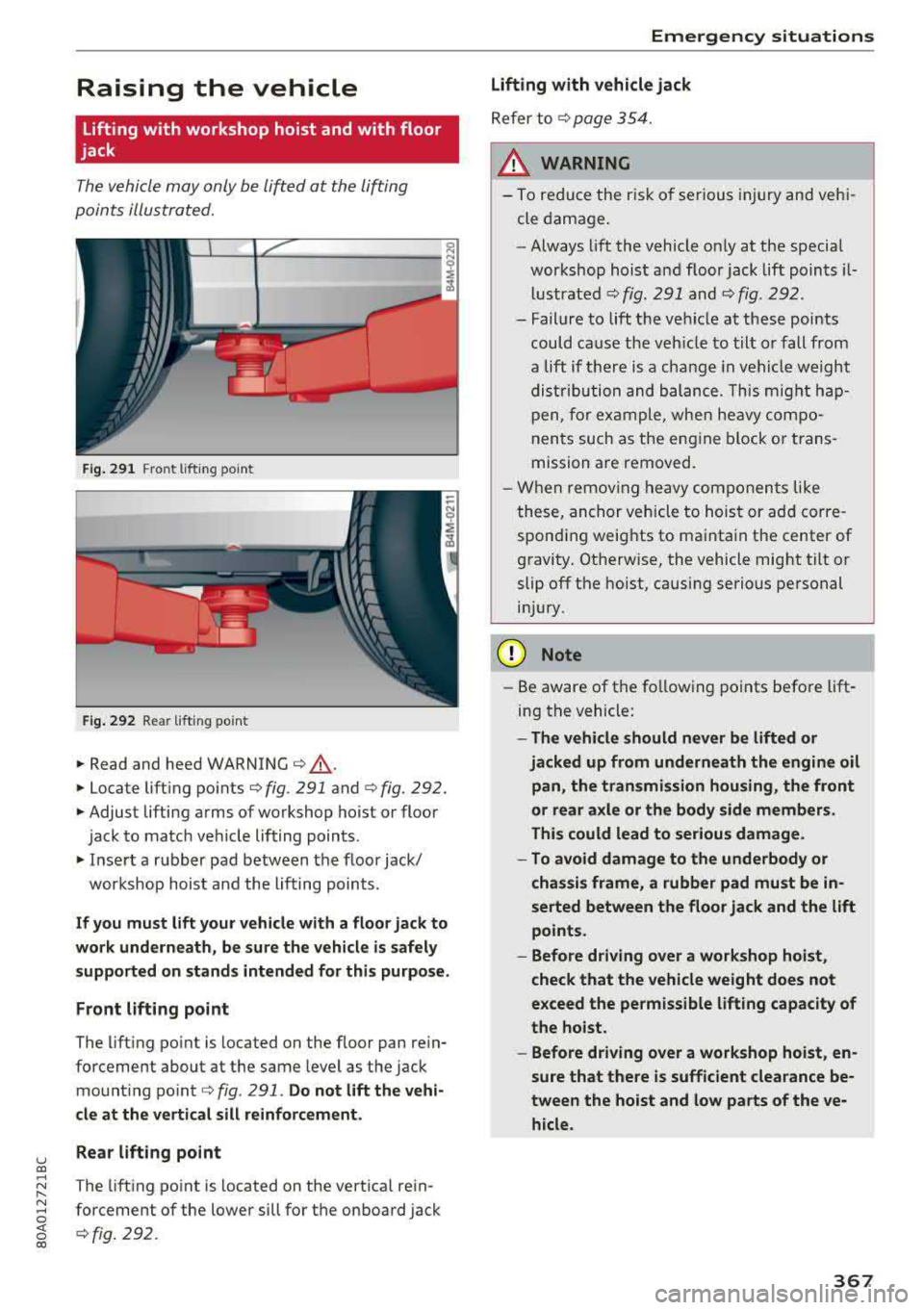
The vehicle may only be lift ed at the lifting
points illus tr at ed.
......_.__ -+,c___------= ------i
cli
Fig. 291 Fro nt lift in g poin t
Fig. 292 Re ar lift ing poin t
.,. Read and heed WARNING c::> &, .
.. Locate lift ing po in ts c::> fig . 291 and c::>fig. 292.
.. Adjust lifting arms of wo rkshop ho ist or floo r
jac k to match veh icle lifting points .
.. Insert a r ubb er pad b etween t he floor jack/
workshop hois t and the lifting points.
If you must lift your vehicle with a floor jack to
work underneath , be sure the vehicle is safely
supported on stands intended for this purpose.
F ront lifting point
The lift ing po int is located on the floor pan re in
forcement about a t th e same leve l as the jack
mo unt ing po int
c::> fig . 291 . Do not lift the vehi
cle at the vertical sill reinforcement.
Rear lifting point
T he lift ing po int is located on the vert ica l re in
forcement of the lower sill fo r th e on board jack
c::> fig. 292 .
Emergency situations
Lifting with vehicle jack
Refer to c::> page 354.
__&. WARNING
- To red uce the r is k of se riou s injury and veh i
cle dama ge.
- Always lift the vehicle on ly at the special
workshop hois t and floor jack lift poin ts i l
l u stra ted
c::> fig. 291 and c::> fig . 292.
- Failure to lift t he ve hicle at these poi nts
could cause the veh icle to tilt o r fall from
a lift if t here is a change in v ehi cle weight
d is tr ibu tion and b ala nce . T his migh t ha p
pen , for ex am ple, when heavy co mpo
nen ts such as the e ngine block o r trans
mission a re removed.
- Wh en remov ing heavy com ponen ts like
t hese, an chor ve hicle to hoist or ad d corre
spond ing weig hts to ma inta in the center of
g ravi ty . Ot herw ise, the vehicle mig ht tilt or
slip off the hoist, causing serious pe rsonal
in ju ry.
(D Note
- Be aware of the fo llow ing points before lift
in g th e vehicle :
-The vehicle should never be lifted or
jacked up from underneath the engine oil pan, the transmission housing, the front
or rear axle or the body side members .
This could lead to serious damage .
- To avoid damage to the underbody or
chassis frame, a rubber pad must be in
serted between the floor jack and the lift
points.
- Before driving over a workshop hoist ,
check that the vehicle weight does not
exceed the permissible lifting capacity of
the hoist.
- Before driving over a workshop hoist , en
sure that there is sufficient clearance be
tween the hoist and low parts of the ve hicle.
367