sensor AUDI Q7 2010 Owner´s Manual
[x] Cancel search | Manufacturer: AUDI, Model Year: 2010, Model line: Q7, Model: AUDI Q7 2010Pages: 390, PDF Size: 93.04 MB
Page 256 of 390
Intelligent technology
'-----------------------------------------------
& WA RNING (conti nu ed )
• Plea se be aware th at in ESP offroad mode , particularly on a
s mooth and slippery road, the wheels may have an incr eased
tendency to spin and the vehicle may break awa y -danger of skid
ding!
• Stabilit y is limited in the ESP offroad mode. •
Electronic differential lock (EDL)
The electronic differential lock monitors the rotational
speed of the drive wheels.
General notes
The electronic differe ntia l lock (EDL) helps the ca r to sta rt moving,
acce lerate and climb a gradient on surfaces provi ding poor or almost
no grip. W ithout ED L, th is would be d iff ic ul t, if not impossible .
How the system works
The EDL operates automatically . It mo nitors the rotational speed of
w heels wi th the help of the ABS sensors ==>
page 256 . If a not iceab le
slip is detected at the wheels (e .g . o n slippery g round on one side),
the spin ning whee ls are braked and power is transferred to the other
wheels. This is done up to a speed of about 60 mph ( 100 km/h) .
Noises from the brake system signa l that wheel spin is being
cont rolled.
Driv ing off
W hen d rivi ng off, always be sure to keep road conditions in mind as
you acce lerate. If one drive wheel spins because it is on a surface with
less grip, apply
plenty of th rottle until t he car starts to move .
Overheating of brakes
To prevent the disc b rake of the bra ked wheel from overhea ting if
subjected to excessive loads on this whee l, t he EDL cuts out tempo
ra rily. The vehicle rema ins operat iona l and behaves in the same way
as a veh icle without EDL. As soon as the brake has coo
led down, EDL sw itches on again auto
m atically.
& WARNING
• When accelerating on slippery surfaces, such as on ice or snow,
always be careful when depressing the accele rator pedal. Even
with the EDL working , the drive wheels c an spin and reduce your
ability to control your car . Risk of crash!
• The increased safety afforded by EDL does not mean that you
can take safety risks . Always adapt your d riv ing style to the road
c ondition s and traffic situation.
[ i ] Tips
If a fa ult occurs in the A BS, the ED L is also no t fu nct io ni ng. This is
ind icated by the ABS warn ing light==>
page 19. •
Anti-Slip Regulation System (ASR)
The Anti- S lip Re gula tion System preven ts the drive n
w heels from spinning when the car is acc ele rating .
General notes
The Anti-S lip Reg ulation Sys tem (ASR) is in tegr ated in the ele ctroni c
stabilization program (ESP) . When the ve hicle starts up and acceler
a tes, the whee ls are p reven ted from sp inning by adjust ing t he engine
power to match the amoun t of grip ava ilable from the road surface.
How the system works
ASR performs automatica lly, i.e. witho ut the driver 's intervent ion.
With the aid o f th e ABS sensors ==>
page 256, ASR moni to rs the speed
of the driven wheels. If the whee ls start to spin, engine torque is
reduced automatically unt il the tires find enough grip to lock onto
the road s urface. The system is active ac ross the en tire speed range .
'1>
Page 261 of 390
_________________________________________ I_ n_ t_ e_ ll_,igent technology ,__E~-
& WA RNING (c on tinued )
planing ). If this should occur, you will have no warning from a
sudden in crease in e ngine speed as with a front -wheel drive
veh icle. Always drive at speeds which are suited to the road condi
tions - risk of crash .•
Energy management
Starting ability is optimized
E nergy ma nagement co ntr ols the distribution of elec
trical energy and thus optimizes the availa bility of elec
trical energy for s tarting the engine.
If a vehicle with a convention al ene rgy sys tem is not driven fo r a lo ng
pe riod of time, the battery is d ischarged by idling cu rr ent consumers
(e.g. immo bilizer) . In ce rtain c ircumstances it can result i n there
being insufficien t energy avai lab le to start the engine .
Inte llige nt ene rgy management in your ve hicl e han dles the dist ribu
ti on of e lectr ica l energy. Sta rting ability is m arkedly improved a nd
the life of the battery is extended.
B as ically , energy managemen t consis ts of
battery diagno sis , idling
current management
and dynamic energy management .
Battery diagnosis
Battery d iagnosis continuously determ ines the state of the battery .
Sensors de term ine ba tte ry vo ltage, ba ttery curren t and batte ry
temperature. Th is determines t he current state of charge and the
powe r of th e battery .
Idling current management
Idli ng cu rrent m anageme nt reduc es ene rgy consu mptio n while the
vehicle is standing. W ith the ignition switc hed off, it controls the
ene rgy su ppl y to the v ari ou s ele ct rical com pone nts. Da ta fr om
battery diagnosis is considered .
Controls and equip
ment Safety first Vehicle operation
Depend
ing on the battery 's state of charge, individual consumers are
gr adu ally t urned o ff to prevent excess ive disch arge of the bat tery an d
t hus maintain start ing capability .
Dynamic energy management
While the vehicle is being dr iven, dynamic energy management
dis tributes the energy gene rated a ccording to the needs o f the in d i
vidua l compo nen ts. It regulates consumpt io n, so that more electr ica l
energy is no t be ing use d th an is being gene ra ted and ensures an
op timal state of charge for the battery .
(I) Tips
• But even energy ma nagement cannot negate the limits o f phys ics .
Consider that t he power and life o f a battery are limited.
• If starting ab ility is threatened, yo u are informed by a warn ing
~ page 260, "D river notification i n the instrument cluste r display" .
What you should know
The high est priorit y is g iv e n to maintaining starting capa
bility .
The b att ery i s seve rely t axed in short -dist ance d riving, in city t raffic
and dur ing the cold time of year . Ab undant electr ica l energy is
re quir ed, bu t on ly a li ttle is generate d. It is also crit ical if t he engine
is not run ning and electr ica l compone nts ar e turn ed on. In this
instance energy is being cons umed but none is being ge ne rated.
It is i n pre cise ly these s itu ations t hat yo u will notice energy m anage
ment act ive ly regulat ing the d istribut ion of ene rgy .
Vehicle stands for an extended period
If yo u do not drive your ve hicle over a period of several days or wee ks,
elect rical compo nents are g radually cut bac k or switched off. This
red uces ene rgy cons umption and ma inta ins start ing capability ove r a
l o nger pe riod.
Vehicle care Do-it-yourself service Technical data
Page 307 of 390
_____________________________________________ C_h _ e_ c_ k_in --= g:-. a_n _d_ f_i _ll _i_n -=g =-- ____.•
- We recommend using only coolant additive Gl2 ++ (check the
l a bel) for yo ur vehicle. This coolant ad dit ive is available at au tho·
r ized Audi dealers . Other types of antifreeze can s ignificantly
reduce corrosion protection. The resulting corrosion can cause a
loss of coolant and serious engine damage .
• Do not add any type of radiator leak sealant to your vehicle's
eng ine coo lant . Adding radiator repa ir fluid may adversely affect the
function and performance of your cooling system and could result in
damage not covered by your New Vehicle Limited Warranty .•
Checking the engine coolant Level
The engine coolant level can be checked with a quick
glance .
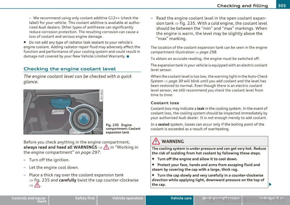
Fig. 2 35 En gin e
c o mpar tmen t: C oolant
ex pansion tank
Before you c heck anything in the eng ine compartment,
always read and heed all WARNINGS~ & in "Working in
the e ngine compartment" on
page 297.
- Turn off the ignit ion .
- Let t he eng ine cool down .
- Place a thick rag over the coolant expans ion tank
~ fig . 235 and carefully twist the cap counter ·clockwise
~ & -
Vehicle OP-eration
-Read the engine coolant level in th e open coo lant expan ·
sion tank ~ fig . 235 . With a cold engine, the coolant level
should be between the "min" and "max" ma rkings . Whe n
the engine is warm , the level may be slight ly above the
"max" marking .
The location o f the coo lant expansion tank can be seen in the engine
compartment illustration=>
page 298 .
To obt ain an accurate reading , the engine must be sw itched off.
Th e expans ion t an k in your vehicle is equippe d with an electric coolant
level sensor.
When the coolant lev el is too low, the warning light in the Auto·Check
System=>
page 30 will blink until you add coolant and t he level has
been resto red to normal. Even though there is an electric coolant
level sensor, we st ill recommend you check the coolant leve l from
time to time.
Coolant loss
Coolant loss may indicate a leak in the coo ling system . In the event of
coo lant loss , the cooling system sho uld be inspected immed iate ly by
your authorized Aud i dea ler . It is not enough mere ly to add coolant.
In a
s ealed system, losses can occu r only if the boiling point of the
coolant is exceeded as a result of ove rheating .
& WARNING
The cooling system is under pressure and can get ve ry hot. Reduce
the ri sk of scalding from hot coolant by following the se steps.
• Turn off the engine and allow it to cool down .
• Protect your face, hand s and arms from e scaping fluid and
s team b y co ve ring the cap with a large, thi ck r ag.
• Turn the cap slowly and ver y carefully in a counter-clo ckwise
direction whil e applying light , downward pre ssure on the top of
thecap .
~
Vehicle care Do-it-yourselt service iTechnical data
Page 336 of 390

lffll __ T_ i_ r_e _s_ a_ n_ d _ w _h _e_e_ l_ s _______________________________________________ _
Tire pressure indicator appears
The tire pressure indicator in the instrument cluster
informs you if the ti re pressure is too low or if there is a
system malfunction.
Fig. 2 44 D ispla y:
u nd erinfl ation
warni ng
Fi g. 2 45 Display:
Syst em m alf un ction
Us ing the ABS sensors, the tire pressure monitoring system compares
t he t ire tread c ircumference and vibrat ion characte rist ics o f the indi
vidual tires. If the pressure decreases in one or more tires, this is indi
cated in the ins trument cl uste r wi th a warning symbol
1 and a
message=> fig. 244 . The dr iver message in the display goes o ut after
5 seconds . T he driver message can be disp layed again by p ressing the
[ CHECK ] button. If only one t ire is affected , the display will ind icate
its position . The tire press
ure monitoring must be reset via MMI each time the
pressu res are adju sted (e.g. when sw itching between partial and full
load pressure) or after chang ing or replacing a t ire on your veh icle
=>
page 335. You can find the recommended tire pressures fo r your
vehicle on the label o n the dr iver's door pillar=>
page 318.
Ti re tread circumference and v ibration characterist ics can change and
c ause a tire p ress ure warning if:
• the tire pressure in one or more tires is too low,
• t he ti re has s tructur al damage,
• the t ire pressure was changed, wheels rotated or rep laced but the
T PM S w as no t rese t=>
page 335.
Warning symbols
' ' Loss of press ure in at least one tir e=> .&. Chec k the t ire or t ires
and rep lace or repair if necessary. The indicator light in the instru-
me nt cluster a lso illumina tes=>
page 14. C heck/co rrect t he p res
sures of all four ti res and reset TPMS via MMI.
( T ire Pressure Monitor ing System)
Tire pre ssure! System
malfunction .
If appears afte r sw itch ing the ignition o n or while
dr iv ing =>
page 334, fig. 24 5 and the indicator ligh t in the ins tru
me nt clus ter blinks for approx imately one minu te and then s tays on,
there is a system ma lfunction . See your a uthorized Audi dealer as
soon as poss ible.
& WARNING
• If the tire pressure indicator appear s in the instrument cluster
display, one or more of your tires is significantly under-inflated.
Reduce your speed imm ediately and avoid any hard steering or
brak ing maneuvers . Stop as soon as possible and check the tires
and their pres sures. Inflate the tire pre ssure to the proper pres
s u re as indicated on the vehicle 's tire pressure label=>
page 318.
Driving on a significantly under-inflated tire cau ses the tire to
overheat and can lead to tire failure . Under-inflat ion also is l ikely
to impair the vehicle 's handling and stopping ability .
~
Page 349 of 390
![AUDI Q7 2010 Owner´s Manual ______________________________________________ F _u_s _e_ s_ a_ n_ d _ b _u_l_b _ s _ ___.1111
(]] Tips
You a re well adv ised to keep a supply of spare fuses in your veh icle .
Fuses wit AUDI Q7 2010 Owner´s Manual ______________________________________________ F _u_s _e_ s_ a_ n_ d _ b _u_l_b _ s _ ___.1111
(]] Tips
You a re well adv ised to keep a supply of spare fuses in your veh icle .
Fuses wit](/img/6/40275/w960_40275-348.png)
______________________________________________ F _u_s _e_ s_ a_ n_ d _ b _u_l_b _ s _ ___.1111
(]] Tips
You a re well adv ised to keep a supply of spare fuses in your veh icle .
Fuses with the proper ampere ratings are available at your authorized
Audi dealer. •
Fuse Location, Instrument Panel left
Fig. 2 59 Fuse pa nel
layou t
Some of the eq uipment items listed a re opt io na l o r only availab le on
certain model configurations.
Note that the following table i s accurate at the time of going to
pre ss and is subject to change . In the event of di scr epancie s, th e
label on the in side of the cover always takes precedence.
Th e power seats are p rotected by circuit breaker s, which a utomat i
cally reset after a few seconds after the overload has been remedied.
No. Equipment
Fuse holder (red)
1
2
Not used
Not used
N ot used
4 T ire pressure monitor ing system
Amps
5
Vehicle OP-eration
No ... Equipment
5 Not used
6 L umbar supp ort dr iver's sea t
7 Window regulators (left side of veh icle)
8 Door control module (left side of vehicle)
9 Not used
1 0 E
lect ronic igni tion lock,
power steering col umn adjustment
1 1 Switch module stee ring column
12 Intell igen t power modu le convenience
Fuse holder (brown)
1 N ot used
2 Not used
3 Seat ventilatio n (left)
4 Wi per system
5 Ra in sensor
6 Horn
7 I ntell igen t po wer mo du le dr ive r
9
10 Intell
igent power module driver
(lights left side of vehicle)
I ntel ligen t power modu le dr iver
(lig hts rig ht side of vehicle)
Instrument cluster
11 Headlight washer system
12 Diagnostic connector
Fu se holder (black)
1 Headlight electronic syst em (left sid e of vehicle)
Vehicle care Do-it-yourself service
Amps
10
35
15
30
10
5
15
30
5
25
30
25
2 5
10
30
10
10
iTechnical data
Page 350 of 390

-Fuses and bulbs ..._ __________________________________________ _
No.
2
3
4
5
6
7
8
9
10
11
1 2
Equipment
Adaptive Cruise Control
N ot used
N ot used
Not used
T erminal
15 (interior)
O il level sensor
D iagnostic connector
Automatic dipping interior mirror H omelink
Control module Gateway
H eadlight range adj ustment
Amps
5
5
5
5
5
5
5
5
Fuse Location, Instrument Panel right
Fig . 260 Fuse pa nel
la yo ut
Some of the equipment i tems listed a re optiona l or only avai lab le on
certain model configu rations .
Note that the following table i s accurate at the time of going to
pre ss and is subject to change . In the ev ent of di screpancie s, the
label on the inside of the co ver always takes preceden ce.
•
The power seats are protected by circuit break ers , which automat i
cally reset aft e r a few seconds af ter the overload has been remed ied.
No . Equipment
Fuse holder (black)
1 Heated rear seats
2 Automat ic transm issio n
3 Front seat hating/seat ventilation (right)
4 Elect ronic Stability Program (ESP)
5 Door con trol module (right side of vehicle)
6 Rear electrical outlets
7 Lumbar support passenger's seat
8 C igarette ligh ter front
9 Front e lectrical outlets
Amps
20
2 0
1 5
25
10
20
25 __________ .__
10 A/C contro ls
11 Not used
12 Intelligent power module passenger
Fuse holder (brown )
1
2
Headlig ht ele ctronic s ystem (r ight side of vehi
cle)
Ride height adjustment
3 Telephone package
4 Audi side assist
5 Elect ronic Stabilization Prog ram (ES P)
6 Automatic transmission
7 Electronic Stabilization Program (ESP)
8 Shift gate automatic transmission
9 Pa rk ing system
10
15
1 0
5
5
5
5
5/20
5
5
5
Page 379 of 390
___________________________________________ A_ l::.. p _h _a_ b_ e_t _ic _a_ l_ in_ d _ e_x __ __
Engine oil level .... ........ .. .. .. .. .. 34
Engine oil pressure
Malfunction .............. .. .. ... . 30
Engine oil sensor defective ............. 34
Engine speed limitation ........... .. .. 34
Entry assist
Rear seats ........ .. ..... .. .. .. .. 89
Environment Break-in per iod .. .. .............. 261
Catalytic converter ... .. .... .. ..... 262
Diesel particulate filter ... .. .. .. .. . 263
Disposing of your vehicle battery . .. . 312
Driv ing at high speeds .......... .. . 264
Driving to minimize pollution and noise .
263
Fuel ....... ...... ... .... ... .. .. . 290
Fuel economy .................... 263
Leaks under your vehicle ........ .. . 297
Letting the vehicle stand and warm up ..
264
Proper disposal of drained brake fluid 308
Proper disposal of dra ined engine coo lant
306
Proper disposal of drained engine oil 302,
303
Recycl ing used engine o il .......... 302
Unleaded fuel . ............... ... 287
What should I do with an old battery? ...
312
EPC
See E lectronic power control ........ 16
ESP
See Electronic stabilizat ion program ( ESP)
16
Controls and equip ment Safety first
Event
Data Recorder (EDR) ........ .... 252
Exhaust tail pipes
Cleaning ........................ 281
Expansion tank .................. ... 305
Exp lana tion of some technica l terms ... 266
Exterior lighting in the mirror housing .. . 68
Eyeglasses compartment .. .. .. .. .. ... 107
F
Fall line ........... ... .. .. ......... 266
Fan Four-zone automatic comfort air conditioning ........... ...... .. 117
Radiator ................ .. .. .. .. 307
Fastening Booster seats ............... ... .. 239
Convertib le child safety seats ....... 23 7
Infant seats .. ................... 236
Filler flap . .. .. .. .. ................. 294
Flat tire Changing .. .. .. ................. 339
Floor mats .................... ..... 194
Fog lights .................. ... .. .. . 67
Folding chocks .. .... ...... ...... ... 336
Folding master key with remote con trol . . 40
Foot pedals .... .................... 194
For the sake of the environment
Gasoline fumes and the env ironment 290
Letting you r engine warm up .. .. .. . 125
Reducing eng ine noise by early upshifting
10
Refueling .. ... ..... .. .. .. ... .... 290 Saving fuel by early upshifting
....... 10
Us ing the rear window defogger . ... 113
Four-zone automatic comfort air conditioning 116
Automatic mode in rear ........... 117
Heated rear seats ................ 120
Rear air distribution ....... .... .. . 117
Rear controls .......... ... .... .. . 116
R ear fan ............ .... ..... ... 117
Rear operation ........ .... .... ... 119
Rear temperature ................ 117
Synchronization .................. 118
Turning on/off ...... .. .. .. .... .. . 116
Front airbags
Description ........ ............ .. 213
How they work ................ .. . 218
Front fog lights ................ ...... 67
Front seats ......................... 83
Adjusting ....................... 191
Child restraints in the front seat .... 211
Fronta l co llisions and the laws of physics 200
Fuel Add itives ....... ........ ... . ... . 287
Blended gasoline . .. .... ......... . 287
Consumption ..................... 37
Filler neck . .. .................... 289
Fu el gauge ...... .. ............... 12
Gasoline ............ ... .. .... ... 287
Gasoline additives . ............... 288
Low fuel leve l . . . . . . . . . . . . . . . . . 12, 33
Octane rating .................... 287
Recommendation .. .............. 287
Refuelling .. ... ... .............. 290
Vehicle operation Vehicle care Do-it-yourself service Technical data
Page 381 of 390
___________________________________________ A_ l::.. p _h _a_ b_ e_t _ic _a_ l_ in_ d _ e_x __ _
Installing the upper tether strap on the
anchorage .....................
250
Instrument cluster illumination ........ 13
Instruments and controls .............. 10
General illustration . ........... .. ... 9
Interior lights Front .............. ...... .. .. .. .. 70
Rear .................. .... ...... 70
Intermittent wiping Rain sensor . ............. .. .. .. ..
72
J
Jack .............................. 336
Jumper cables ...................... 353
Jump-starting ...................... 352
K
Key ...... ...... .... .. .. .. .... .. .. .. 40
Battery replacement .. .. .... ....... 42
Coded settings ............ ...... . 109
Convenience opening and closing of
windows ......... .. ... ... ... ... 58
Emergency key ................ .. ..
40
Key replacement .................. 40
Master key ......... .. .. .. .. .... .. 40
Valet key .................... .... 40
Key coded settings
Climate controls .................
109
Keyless entry remote contro l ... .. .... .. 41
Kick-down
tip tronic ® ... ................... .
164
Controls and equip
ment Safety first
L
LATCH
............ ... ... .......... 244
Description ......................
245
Guidance fixtures for lower anchorages . .
246
Installing a child restraint ......... 248
Location ...................... .. 245
Mounting and relea 1sing the anchorage
hook ........................ .. 248
Lateral angle ........... .... ........ 266
Leather ...... .. .. ...... .. ... ...... 283
Cleaning ..... ........... ........ 284
Level adjustment
See Adaptive Air Suspension ........ 176
Lifting jack .. .................. ... .. 342
Lift ing vehicle ...................... 357
Light
Exterior lighting in the mirror housing . 68
leaving home .................. .. . 68
See also Ambience lighting ......... . 71
Light sensor defective ................ 33
Lighting
See Ambience lighting ............. 71
Lighting in the mirror housing .......... 68
L ights .......................... ... . 65
Coming home ........ ...... ... ...
66
Daytime running lights ... .. ... ..... 66
Emergency flashers ............. .. . 68
Exterior lights ....................
66
Front fog lights . ...... ............ 67
Headlights ....... ................ 65
High beam . . . . . . . . . . . . . . . . . . . 65, 69 High beam warning/indicator
light ...
19
Leaving home ..................... 66
Rear fog lights ........... ... ...... 67
Side marker lights .......... .. ... .. 65
Turn signals .............. .... .. .. 69
Xenon headlights . .. .......... ..... 65
Loading the lugg age compartment .....
195
Loading the roof rack ................ 101
Locking
Power locking switch ........... .. ..
47
Rear lid/trunk lid ... .. .. ........... 49
Remote control key .... .... .. .. .. .. 45
Using the key ..................... 46
Lower universal anchorage bars (Canada) .. .
244
Lower universal anchorages (Canada) .. . 244
Luggage Stowing ........................
195
Luggage compartment ................ 94
Cargo net ........................ 96
Expanding .. ...... ...............
94
Retractable cover .. .. .. ........... 96
Ski sack .................. ...... .. 99
See also Loading the luggage
compartment ..................
195
luggage compartment
Tie-down rings . .................. .
95
M
Maintenance ....................... 366
Malfunction Indicator Lamp (MIL) ...
17 , 26
Vehicle operation Vehicle care Do-it-yourself service Technical data
Page 383 of 390
Alphabetical index fflll ___________________________________ ____._ _______ _
Power locking system .. .. .... .... ... .. 44
Convenience close/open feature .. .... 58
Locking and unloc king the veh icle from
inside ..... .. .. ... .. .. .. .... .. ..
47
Opening and closing the windows . .. . 58
Rear lid/trunk lid .... .. .. .. .. .. .. .. 49
Remote control key .. ...... .. .... .. 41
Selective unlock feature .. ...... .. ..
47
Sett ings .. .. ... .... ..... .. .. . .... 47
Unlocking a nd lock ing vehicle .. .. .. .. 45
Power outlets ............. .. .. .. .. . 104
Power seat Con tro ls .. .. ........... ...... .. ..
84
Sea t adju stmen t .... ...... .. .. .. .. 85
Power steering ..... ... . .... ... .. .. . 257
Power window switches . ..... .. .. ..... 56
In the driver's door ........... .... . 56
In the front passenger 's door .... .. .. 57
Reactivating the system .. ...... .. .. 59
Pregnan t women
Special considerations when wearing a safety be lt ..... ... .. ... ... .. .. . 205
Programming the Homelink ® universa l re-
mote cont rol .......... .. .... .. . 183
Proper occupant seating pos it ions . .... . 190
Proper sa fe ty belt posi tion ......... .. . 2 04
Prope r seat ing position
Front passenge r .. .. .... ......... . 191
Oc cupants ......... .. .. .. ... ... . 190
Rear passe ngers .. ...... ....... ... 19 2
Protective tray ............... .. .. .. .. 97
Controls and equip
ment Safety first
Q
Quartz clock
...... .................. 11
quattro ®
See All Whee l Drive ....... .. .... .. 258
Ques tion
Wh at happe ns to u nbe lte d occ upan ts? . .
201
Why safety belts? ................ 199
R
Rad iator fan .. .... .... ......... .... 307
Rain sensor ... .. .. .... ... . ... .... .. . 72
Rain sensor defe ctive ........ ...... .. . 33
Readi ng lights
Front ........................... 70
Rear .. .. .. .. .. .... ... ... .... .. .. 70
Rear ashtray . ... .... .. .. .. .. .. .. ... 103
Rear fog lig hts .. ....... .... .. .. .. .. . 67
Rear lid Automatic operation ............ .. . 50
Emergency unlocking .. .. .. ... ... .. 52
Ope ning and closing .............. . 49
Valet key funct ion ...... ... ........ 43
Rear light Defective .. .. .. ... ... ............ 24
Rear ope ra tion
Four -zone automatic comfort air
conditioning ...... ... ... .... .. . 119 Rear park assist ..
... ..... ... ... .. .. . 168
Adjusting the display ....... .. .. ... 17 4
Adjusting the warning tones ........ 17
4
Trailer hitch . .. .. .. .. .. ... ..... .. 175
Rear seats Adjusting seat ...... ...... .. . ... .. 88
Entry assist . .. .. .. ............... 89
Folding seat back up and down .. .. ... 90
Rear view camera Parking mode 1 . ... ...... ... . ... . 172
Parking mode 2 . ... ...... .. .. ... . 173
Re ar view mir ror
I ns ide rear view m irro r . . . . . . . . . 7 7, 78
Rear window defogger ............. .. 113
Red symbols ... .. .. .. ...... .. .. ... .. 28
Ref ue lli ng ... .... ........... .... .. . 290
Gaso line inh ibitor fl ap ............ . 290
Release lever for hood . ....... .. .. .. . 296
Remote cont rol ga rage door o pener
(Homeli nk® ) .... ....... ... .. ... 183
Remote control key ... ... .... ... . .. ... 41
Unloc king and locking ... .. .. .. .. .. .
45
Remote rear lid release ............... 49
Repa ir manuals ..... .... ... .. .. .. ... 366
Repai rs
Airbag system ..... .. . .... .... .. . 223
Rep lacing a fuse ....... .. .. .. .. .. .. . 346
Replacing light bulbs .. .. .. .......... 350
Rep lacing tires and w heels .. .......... 3 26
Report ing Safety Defects . . . . . . . . 19 7, 198
Reset button ...... . .. .. .. .. ... .... .. 12
Residua l heat .. .. .. .. .............. 110
Vehicle operation Vehicle care Do-it-yourself service Technical data
Page 384 of 390
___ A_ l_. p_ h _ a_b_ e_ t_ic _a_ l_ in_ d_e _ x ____________________________________________ _
Retractor ... .. .. ....... ... ... ... . .. 203
Rims
Cast alloy .......................
280
Roof rack . .. .................... ... 100
Loading ..... ................. .. 101
Mounting locations . .. .. .. .. .. .. . .
Roof weight ....... ... ............ . 101
101
266
Rule of behavior offroad
s
Safe driving habits ... .. .. .. ......... 188
Safety belt height adjustment .. .. ..... 206
Safety belt position .. .. .... ......... 204
Safety belt height adjustment ...... 206
Safety belts worn by pregnant women ...
205
Safety belt pretensioner ............. 207
Service and disposal ........ .... .. 208
Safety belt warning light .... .. .. .. 18, 199
Safety belts ... ................... .. 203
cleaning ...................... .. 285
Danger to passengers who do not wear a
safety belt ............ ... ... ...
201
Fastening ......... .............. 203
Improperly worn .. .... .. ......... 207
Not worn .... ................. .. 201
Safety belt position ....... .. .. .. .. 204
Safety instructions ............ ... 202
Securing child sa fety seats ......... 241
Special considerations for pregnant Why YOU MUST wear them .
.. .. .. .
199 Seating capacity . ....... .. .. .. .. .. .. 199
Worn properly ............... ... . 202 Seating position
Safety compliance sticker ............
360 Driver ... ....................... 190
Safety equipment ................... 188 Front passenger . . . . . . . . . . . . . . . . . 191
Safety features for occupant restraint and How to adjust the
front seats ...... 191
protection . .. .. ........ ....... . 188 Incorrect seat position ... ......... 193
Safety guidelines Occupants .
.. .. .... ............. 190
Seat adjustment ................ .. 83 Rear passengers 192
Safety instructions Seats
Engine compartme nrt ...... .. .. .. .
297 Number of seats . ... ............ . 199
for side curtain airbags ........... . 230 Selective unlock feature .. .. ..... .. ... 47
for using child safety seats .. .. .... . 234 Selector lever ... .... .. ........... .. 162
for using safety bel ts ... .. ... .. .. . 202 Service and disposal
Monitoring the Advanced Airbag System Safety belt pretensioner .......... .
208
222
Safety lock
Ignition key, automatic transmission
125
Seat adjustment
Adjusting the seat height manually ...
86
Adjusting the seatback manually . .. .. 86
Driver's seat .............. ....... 83
Driver 's seat memory ............ .. 87
Front passenger's seat .. .. .. ..... .. 84
Front seats . . . . . . . . . . . . . . . . . . . . . . 83
Head restraints ......... .. .. .. 90, 193
Manual controls . ................. 86
Moving the seat forward or backward
manually ............ ........ ...
86
Power .. .. .. ... .... ...... .. ... ... 84
Seat be lts
See Safety be lts ................ . 199
Service interval display . ........... .. . 25
Service position
Windshield wipers .. .... .......... 75
Servotron ic
Power steering ....... ... .. .... ..
257
Shift buttons ..................... . 166
Side airbags
Description ........ .............
225
How they work ............ .... .. 226
Side ass ist
Activating and deactivating ........
152
Description . ... ................. 152
Informational and alert stage signals 154
Messages in instrument cluster display ..
159
MMI settings ........ .. .... .... .. 158
women .. ..... ........ ...... .. 205 Seat memory ................ ..... . . 87
Operation ..... ................ . 154
Safety tips ..... ... ............. . 160
Unfastening · · · · · · · · · · · · · · · · · · · · · 206 Seat vent ilation .. ..... ........ .. .. . 119
Warning/ind icator light .. ......... 199 Sensor detection area ............ . 154