buttons AUDI Q7 2014 Owner´s Manual
[x] Cancel search | Manufacturer: AUDI, Model Year: 2014, Model line: Q7, Model: AUDI Q7 2014Pages: 340, PDF Size: 85.02 MB
Page 142 of 340
140 Automatic transmission
-Never hold the vehicle on an incline with
a slipping clutch. The clutch opens auto
matically when it becomes too hot from
the overload. An indicator lamp
[O] illu
minates and a driver message appears
c!;> page 141 when the clutch is overload
ed.
- If the engine must remain running, never
have any driving position engaged when
checking under the hood. Make sure the
selector lever has securely engaged and
is locked in P with the parking brake
firmly set¢
page 257. Otherwise, any
increase in engine speed may set the ve
hicle in motion, even with the parking
brake applied.
(D Note
- When stopping on an incline, do not try
to hold the vehicle in place by pressing
the accelerator peda l while a driving gear
is selected. This can cause the transmis
sion to overheat and can damage it. Acti
vate the park ing brake or press the brake
pedal to prevent the vehicle from rolling.
- Allowing the vehicle to roll when the en
gine is stopped and the selector lever is
in
N will damage the transmiss ion be
cause it is not lubricated under those cir
cumstances.
Hill descent control
The hill descent control system assists the
driver when driving down declines.
H ill descent control is activated when these
lector lever is in D/S and you press the brake
pedal. The transmission automatically selects
a gear that is suitab le for the incline. Hill de
scent control tries to maintain the speed ach
ieved at the time of braking, within physical
and technical limitations . It may st ill be nec
essary to adjust the speed with the brakes.
Hill descent control switches off once the de
cline levels out or you press the accelerator pedal. When the speed
is set in the cruise control
system
c!;>page 111, hill descent control is al
so activated.
A WARNING
--
Hill descent control cannot overcome
physical limitations, so it may not be able
to maintain a constant speed under all
conditions. Always be ready to apply the brakes.
· Manual shift program
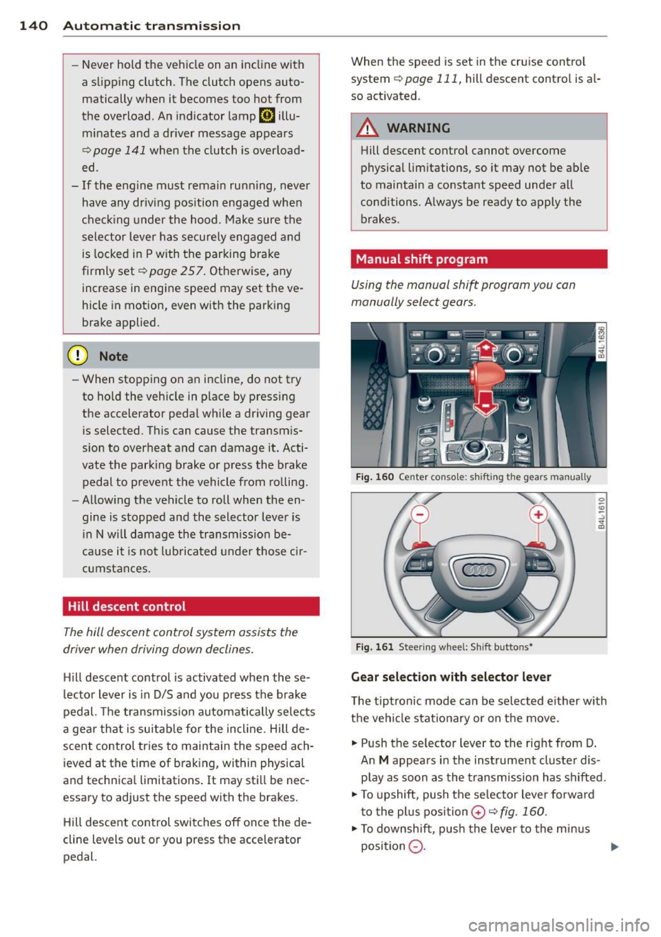
Using the manual shift program you can
manually select gears.
Fig. 160 Center console: shift ing the gears manually
Fig. 161 Steering wheel: Sh ift buttons•
Gear selection with selector lever
The tiptronic mode can be selected either with
the vehicle stationary or on the move.
.,. Push the selector lever to the right from D.
An
M appears in the instrument cluster dis
play as soon as the transmission has shifted .
.,. To upshift, push the se lecto r lever forward
to the plus position
0 c!;> fig. 160 .
.,. To downshift, push the lever to the minus
position
Q . 1J>-
Page 143 of 340
Gear selection with paddle levers*
The shift buttons are activated when these
lector lever is in D, Sor the tiptronic manual
shift program .
.,. To upsh ift, touch the button on the right
0
¢fig. 161.
.,. To downshift, touch the button on the left
0-
... If you do not press a shift button within a
short time while in the Dor S position, the
transmission will return to automatic mode .
To keep shifting using the shift buttons, move the selector lever to the right out of
the D position.
The transmission automatically shifts up or
down before critical engine speed is reached.
The transmission only allows manua l shifting
when the engine speed is within the permit
ted range.
(D Tips
- When you sh ift into the next lower gear,
the transmiss ion will downshift only
when there is no possibility of over-rev
ving the engine .
- When the kick-down comes on, the
transmission will sh ift down to a lower
gear, depending on vehicle and engine
speeds.
- Tiptronic is inoperat ive when the trans
mission is in the fail-safe mode .
Kick-down
Kick-down enables maximum acceleration.
When you depress the accelerator pedal be
yond the resistance point, the automatic
transmission downshifts into a lower gear, de pending on vehicle speed and engine speed.
The upshift into the next higher gear takes
p lace once the maximum spec ified eng ine
speed is reached.
Autom atic transm ission 141
A WARNING
Please note that the drive wheels can spin
if kick-dow n is used on a smooth slippery
road -there is a risk of skidding .
Transmission malfunction
[O] Transmission malfunction: You can con
tinue driving
There is a system malfunction in the transmis
sion. You may continue driving . Drive to your
authorized Aud i dea ler or qualified repair fa
cility soon to have the malfunction corrected.
[O] Transmission malfunction: limited driv
ing functionality
There is a system malfunction in the transmis
sion. The transmission is switching to emer gency mode . This mode only shifts into cer
ta in gears or will no longer shift at all. The en
gine may sta ll. Drive to your authorized Audi
dealer or qualified repair facility immediately
to have the malfunction cor rected.
(D Note
If the transmission switches to emergency
mode, you should take the vehicle to an
a utho rized Aud i dealership as soon as pos
sible to have the condition corrected.
Selector lever emergency release
If the vehicle's power supply fails, the selec
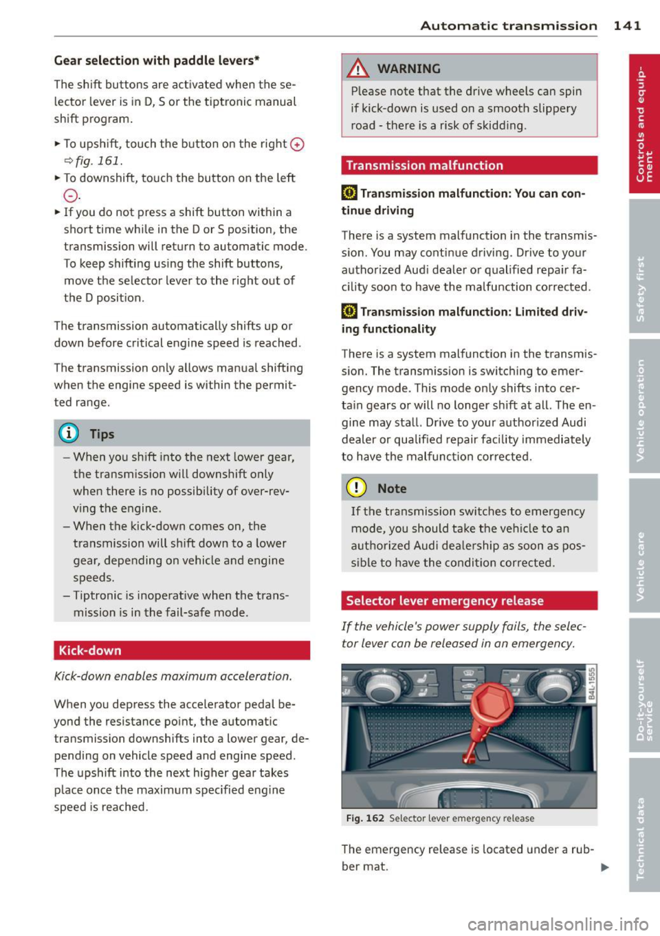
tor lever can be released in an emergency.
Fig. 162 Selector lever emergency release
The emergency release is located under a rub-
ber mat. ..,.
Page 163 of 340

Homelink
Universal remote
control
Description
Applies to vehicles: with Home link
The HomeLink universal remote control can
be programmed with the remote control for
devices that are already present.
With Home Link, you can control devices such
as the garage door, security systems, house
lights , etc. comfortably from the inside of you
vehicle.
Homelink makes it possible for you to rep lace
three different remote controls from devices
in your home with one universal remote. This
feature works for most garage door and exte
rior door motor signals. Programming the in
dividual remote control for your remote con
trol takes place on the left side of the front bumper. There is a control module attached at
this location .
A one-time programming of the sensor must be performed before you are able to use sys
tems with Homelink. If the system does not activate after performing the one-time pro
gramming, check whether the system uses a rolling code
¢ page 163 .
A WARNING
-Never use the Homelink transmitter
with any garage door opener that does
have not the safety stop and reverse fea
ture as required by federa l safety stand
ards. This includes any garage door open
er model manufactured before April 1,
1982.
- A garage door opener which cannot de
tect an object, signaling the door to stop
and reverse does not meet current feder
al safety standards . Using a garage door
opener without these features increases
risk of serious injury or death.
Homelink 161
- For safety reasons never release the
parking brake or start the engine while
anyone is standing in front of the vehicle .
- A garage door or an estate gate may
sometimes be set in motion when the
Homelink remote control is being pro
grammed. If the device is repeatedly ac
tivated, th is can overstrain motor and
damage its electrical components - an
overheated mo to r i s a fire hazard!
- To avoid possib le injuries or property
damage, please always make abso lutely
certa in that no persons or objects are lo
cated in the range of motion of any
equipment being operated.
(0 Tips
- If you would like more information on
Homelink, where to purchase the Home
Link compat ible products, or would like
to purchase the Home Link Home Light
ing Package, please call toll-free :
1-800-355-3515.
- For Declaration of Compliance to United
States FCC and Industry Canada regula
tions
¢page 319.
-For security reasons, we recommend that
you clear the programmed buttons be
fore selling the vehicle.
Operation
App lies to vehicles : with Homeli nk
111111 111111
-
Fig. 191 Headl iner: controls
Req uirement: The buttons must be program
med
<:!)page 162.
Page 164 of 340

162 Homelink
• To open the garage door, press the p rogram
med button . The LED @will light up or
flash.
• To close the garage door, pre ss the button
again.
@ Tips
To open the garage door, press the button,
but do not press it for longer ten seconds
or the Homelink module will switch to
programming mode.
Programming the transmitter
Applies to vehicles: with Home link
F ig . 192 Dis ta n ce between t he b umper an d th e hand
t ransm itter
Programming: phase 1 on th e control unit
1. Sw itch on the ignit ion (do not start the
engine) .
2. Pr ess and hold both of the outer Home
L ink bu ttons
~ page 161, fig. 191 unt il
the L ED @ turns off comple tely (abo ut
20
seconds). Th is procedure clears the stand
ard codes that were set at the facto ry a nd
does
not need to be repeated again to
program the other buttons .
3. Briefly press the Homelink bu tton th at
you would like to program .
4. Wait unti l the LED @beg ins to blink
q ui ck ly. The Homelink modu le w ill now
r emai n in learning mode for
5 minu tes.
5 . Now s tand in fron t of yo ur vehicle wi th
the orig inal hand t ransmit ter for the ga
r age door opener or for the device that
you would l ike to allocate to the Home
Link button.
Programming: phase 2 on the bumper
6. Hold t he or iginal hand transm itter to
war ds the left headlight and the radiator
gr ille ~
fig. 192 .
7. Now activate (press) the hand transmit
ter.
8. Pay attention to the turn signa ls for your
vehicle when activating the hand trans mitter . If the eme rgency flashers blink
three t imes, the programmi ng was suc
cessf ul. If the e mergency flashe r on ly
b links one time, the
5 m in ute time lim it
f or the adap tation has expired or the pro
gramming was unsuccessful. Repeat the
programming from step
3 on the controls
o r select another distance from the
bumpe r.
9. If the garage door or other dev ices st ill
fail to be activated w it h the Home Link
control buttons after prog ramming is
comple ted, it is possib le that these sys
tems might be wor king wi th a rolling code
i ns tead of the n ormal fixed code.
A Roll
ing code programming m ust be per
f ormed
~ page 163 .
Progra m the remaining two buttons ac cord ing
to t he inst ructions ment io ned a bove. Beg in
s imilarly w ith the 3rd step if the program
ming connec tion was successful for the firs t
button.
Remote con tro l units for garage do or ope ners
in Canada are set to stop transmi tting radio
frequency signa ls after two seconds. This time
may not be suffic ie nt for the Homelink sys
tem to learn the radio frequency signa l. Per
form all other steps as desc ribed above.
Erasing the buttons
• Switch on the ignition (do not s tart the en
gine).
• Press and hold both of the outer buttons un
til the LED @turns off completely (abo ut
20 seconds) to erase a ll of the buttons si
mu lt aneously .
• Prog rammed buttons ca nnot be erased ind i
vidually . Reprogram the buttons if necessa-
ry .
II>
Page 165 of 340
Reprogramming the buttons
"' Switch on the ignition (do not start the en
gine).
"'To reprogram an individual button, press
and hold the button until the LED@starts
to flash quickly (after about ten seconds).
Release the button immediately. The Home
Link module will now remain in learning
mode for 5 minutes.
"'Continue with step 5 .
@ Tips
- The required distance between the hand
transmitter and the Homelink module in
the bumper ¢
fig. 192 depends on the
system that you are programming .
- Depending on the model of the garage
door opener, you may need to release the
button on the remote and press it again
when programming. When program
ming a new device, keep the button
pressed for at least 15 seconds before
trying again with the transmitter in a dif
ferent position. Watch out for the emer
gency flasher during that time.
Programming the rolling code
App lies to vehicles: with Home link
Additionally, a rolling code programming for
the Homelink universal remo te control is re
quired for some systems.
Identifying the rolling code
"'Press the previously programmed Homelink
button again and hold it down .
"' Look at the LE D @ ¢
page 161, fig. 191 . If
the LED blinks quickly, the features, such as
the garage door opener, are equipped wi th
the rolling code .
"'Program the rolling code as follows:
Activating the garage door opener motor
unit "'Locate the setting button on the garage
door opener motor unit . The exact location
and color of the button may vary depending
on the garage door opener manufacturer .
Homelink 163
"' Press the setting button on the garage door
opener motor unit (usually this will activate
a "setting light display" on the motor unit).
Now you will have about 30 seconds time to
perform the Homelink button programming
on the controls .
Programming on the controls
"'Press the Home link button that was already
programmed and hold for two seconds.
"'To end rolling code programming, press and
hold the Homelink button for two seconds
again.
"'The Homelink button may need to be press
ed a third time to end the adjustment proce
dure for some garage door openers .
After the controls have been programmed, the
garage door opener should recognize the HomeLink signal and operate when the Home
Link button is pressed. Now you may program
the other buttons as needed.
@ Tips
- Programming the rolling code can be
performed quicker and more easily with
the help of a second person.
- If difficulties should arise when pro
gramming the rolling code, consult the
operating instructions for the garage
door opener or other devices for possible
solutions.
Page 220 of 340
218 Child Safety
-Always follow the instructions provided
by the manufacturer of the ch ild re
straint you intend to install in your veh i
cle.
- Never install a child restraint without a
properly attached top tether strap if the
child restraint manufacturer's instruc
t ions requ ire the top tether strap to be
used.
- Improper use of child restra int LATCH
lower anchorage points can lead to injury
in a collision. The LATCH lower anchorage
points are designed to withstand only
those loads imposed by correctly fitted
child restraints.
- Never mount two child restraint systems
on one LATCH lower anchorage point.
- Never secure or attach any lu gg age or
other item to the LATCH lo wer anchorag
es .
(j) Tips
-In Canada , the terms "top tether" with
"lowe r universal anchorages " (or " lower
un iversa l anchorage bars") are used to
describe the system.
- In other countries, the term "ISOFIX" is
u sed to describe the lower anchorages.
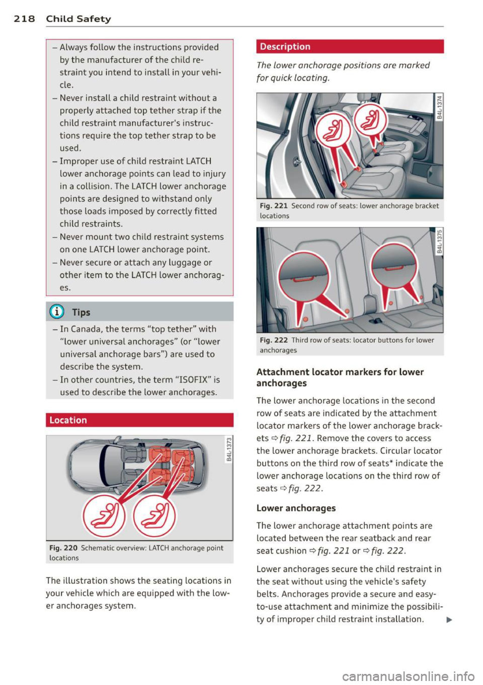
Location
Fig. 220 Schematic overview: LATCH an ch orage point
locations
The illustration shows the seating locations in
your vehicle which are equipped with the low er anchorages system.
Description
The lower anchorage positions are marked
for quick locating.
Fig. 221 Second row of seats : lower ancho rage bracket
loc ations
Fig. 222 Thir d row of seats: locator butto ns for lower
anchorages
Attachment locator markers for lower
anchorages
T he lower anchorage locations in the second
row of seats are indicated by the attachment
locator markers of the lower anchorage brack
ets¢
fig. 221. Remove the covers to access
the lower anchorage brackets. Circular locator
buttons on the third row of seats* indicate the
lower anchorage locations on the third row of
seats
¢fig. 222.
Lower anchorages
The lower anchorage attachment po ints are
located between the rear seatback and rear
seat cushion
9 fig. 221 or¢ fig. 222.
Lower anchorages secure the chi ld restraint in
the seat without using the vehicle's safety
belts. Anchorages provide a secure and easy
to-use attachment and minimize the possib ili-
ty of improper child restra int installation.
II>
Page 324 of 340
322 Index
Alcantara Cleaning 247
All-wheel drive . ........... .... .... . 228
Winter tires
Alternator 288
Malfunction . . . . . . . . . . . . . . . . . . . . . . . 31
Ambience lighting Lighting profiles .......... .... .... .. 62
Anti-freeze
refer to Engine coolant system ....... 264
Anti-lock brake system ...... .. .. .. .. . 224
Warning/indicator lights . . . . . . . . . 16, 18
Anti-slip regulation ........ .. .. .... . 224
Warning/indicator lights ... .. .. .. .. .. 16
Anti-theft systems Anti-theft alarm system . . . . . . . . . . . . . SO
Electronic immobilizer ............. .. 40
Approach/departure angle . .. .. .. .. .. . 237
Ashtray . .. ... ............ .. .. .. .. .. 87
Asterisk What does it mean when something is
marked with an asterisk? . . . . . . . . . . . . . . 6
Audi braking guard ....... .. .. .. .. .. . 127
Error messages .............. .... . 128
Settings . . . . . . . . . . . . . . . . . . . . . . . . . 128
Status messages . . . . . . . . . . . . . . . . . . 128
Switching on and off ...... .. .. .. .. . 128
Audi Service Repair Manuals and Litera-
ture .. .. .. .. ............. .. .. .... . 316
Auto -Check Control . . . . . . . . . . . . . . . . . . 30
Automatic belt retractor ..... .... ... . 178
Automatic mode
Four-zone automatic comfort air condi-
tioning ........................... 99
Automatic Shift Lock (ASL) . . . . . . . . . . . 138
Automatic transmission ..... .. .. .... . 137
Automatic Shift Lock (ASL) . .. .. .. .. . 138
Driving .. ................. .. .... . 139
Emergency mode .......... ... .. .. . 141
Emergency release ......... ... .. .. . 141
Hill descent control ........... .. ... 140
Ignition key safety lock ...... .. .. .. . 105
Kick-down .. ... .......... .. .. .. .. . 141
Manual shift program ......... .. .. . 140
Selector lever .................... . 13 7
Shift buttons . . . . . . . . . . . . . . . . . . . . . 140 AUTO mode
A/C climate controls ............ ... . 95
Auto Safety Hotline ............. .... 171
Average speed . . . . . . . . . . . . . . . . . . . . . . . 24
Avoid damaging the vehicle ........ ... 234
B
Bass box
Battery .... .. .. .. .. ........... ... .
Battery location .. ................ .
Charging ...... .. .. ... ........... .
Important warnings when working on
the battery .... .. ............. ... . 295
268
269
270
269
Jump starting .. .. ... .......... .. .. 307
Low ..... ..... ............... .... 229
Replacing the battery .............. 272
State of charge ................... . 229
Voltage ... .... ................... . 35
Winter operation . ............. .... 268
Working on the battery .. .... ... .. .. 269
Before driving ..... ............. .... 164
Blended gasoline .. ................ . 249
Booster seats . . . . . . . . . . . . . . . . . . . . . . 212
Brake fluid
Changing the brake fluid ............ 268
Checking the brake fluid level ..... ... 267
Reservoir ... .. .. .. .............. . 267
What is the correct brake fluid level? .. 267
What should I do if the brake fluid warn-
ing light comes on? ...... ...... .. .. 267
Brake light Defective . . . . . . . . . . . . . . . . . . . . . . . . . 23
Brake system .... ... .............. .. 267
Anti-lock brake system . . . . . . . . . . . . . . 18
Brake assist system ................ 224
Brake booster .... ............. .... 226
Brake fluid . ..... ................ . 267
Brake fluid specifications for refill and re-
placement .... .. ............. .... 268
Brake pads .. .. .. ..... ........... . 232
General information .............. . 226
How does moisture or road salt affect the
brakes? . .. .. .. .. ............. .. .. 226
Malfunction . . . . . . . . . . . . . . . . . . . . . . . 32
Parking brake .. .. ... .......... .. .. 109
Warning/indicator lights ............. 19
Worn brake pads symbol . . . . . . . . . . . . . 36
Page 334 of 340
332 Index
Selective catalytic reduction
refer to Ad Blue . ....... ... .. .. .... . 254
Selective unlock feature ..... .. .. .... .. 44
Selector lever . . . . . . . . . . . . . . . . . . . . . . 13 7
Emergency release ................. 141
Service and disposal
Safety belt pretensioner ... .. ... ... . 18 1
Service interval d isp lay ................ 23
Service pos ition
W indshield wipers ............ .. .... 66
Servotronic Power steering .. ...... ... .. .. .... . 228
Shift buttons ... ........... .. .. .... . 140
Shutting down vehicle ............... 234
Side airbags Description .... .. ..... ... .. .. .... . 198
How they work .................... 200
Side assist Activating and deactivating ... .. .. .. . 129
C leaning the sensors .. .. .. .. .. .... . 245
Description .... . ...... ... .. .. .... . 129
Informational and alert stage signals . 131
Messages in instrument cluster d isplay 135
MMI settings .............. .. .... . 134
Operation . . . . . . . . . . . . . . . . . . . . . . . . 131
Safety t ips .... ... .... ... .. .. .. .. . 136
Sensor detection area .............. 130
Side curta in airbags
Descr ip tion ................ .. .... . 201
H ow they work ................ .... 202
Safety instructions ..... ... .. .. .. .. . 203
Side curtain airbags) ........ .. .. .... . 201
Side ma rke r lights ................... 57
Ski sack ... ... ... ...... ..... .. .. .. .. 83
Snow chains .. .. .. ..... ... .. .. .... . 289
Sockets ... .. ................ ... .... 88
Sound system display
Driver information display ...... .... .. 21
Sources of in fo rmat ion about ch ild re-
straints and their use ..... .. .. .. .. .. . 223
Speed control system
refer to Adaptive cruise cont ro l .. .... . 113
Speedometer .............. ..... .. .. 12
Speed rating letter code ... .. .. ... ... . 285
Speed warn ing system .......... .. .... 28 Starting on h
ills
Hill ho ld .. .... .. .. ... ..... ... .. .. 110
Starting the engine . . . . . . . . . . . . 105, 106
What shou ld I do if t he engine does not
sta rt? .... .... .. ............. .... 106
Steering ........... ............... . 103
Easy entry feature ................. 104
El ectr ica lly adjust ing the stee ring
whee l ... ..... .. ............. .... 103
Locking the stee ring ........... .. .. 105
Malfunc tion ..... .. ... ..... ... .. .. . 33
Manua lly adjusting the steering wheel . 103
Stee ring wheel column
Adjusting ele ctrically ........... .. .. 103
Adjus ting ma nually ............ .... 103
Steering wheel heat ing ............. . 102
Steps for determining correct load limit . 282
Stopp ing the eng ine ............. .... 106
Storage .... .... .. ............. .... . 88
(upholder ........ ............... .. 86
(upholder door pockets ............ .. 87
(upholder in the rear center conso le .. . 79
( upholder rea r cente r a rm rest . .. .. .. . 86
G love comp art me nt ............ .. .. . 89
Storage compartment
Expand ing .. .. .................... 80
Storage net Footwell . . . . . . . . . . . . . . . . . . . . . . . . . . 90
Luggage compartment ............. . 91
Seatbacks ... ... . .. .... .... ... .. .. . 91
Su nroof
refer to Panoramic sliding sunroof . ... . 54
Su n shade .. .... .. ............. .... . 63
Sunshade Panoramic sliding sunroof . . . . . . . . . . . . 56
Sun v isors .. .... .. .. ... ..... ... .. .. . 62
Suppleme nta ry heater
Climate controls .. ............. .... 101
Suspension
refer to Adapt ive A ir Suspension . 155, 157
Switches Emergency flashers . . . . . . . . . . . . . . . . . 60
Rear window defogger .......... ..... 96
Symbols Red . ... .. .... .. .. ... ..... ... .. .. . 31
Ye llow . ... .... .. .. .... .... ... .. .. . 34