display AUDI Q7 2014 Owner´s Manual
[x] Cancel search | Manufacturer: AUDI, Model Year: 2014, Model line: Q7, Model: AUDI Q7 2014Pages: 340, PDF Size: 85.02 MB
Page 155 of 340
Adjusting the display and warning tones
Applies to vehicles: with rear park assist/Audi parking sys
tem plus with rearview camera/front- and rearview cam
era
The display* and warning tones can be ad
justed in the MMI.
~ Select: ICARI function button> Systems*
control button > Parking system. Or
~ Select: ICARI function button> Car systems*
control button > Driver assist> Parking aid.
Display*
- Off -when the parking system is switched
off, only audible signals are given.
-On -when the parking system is switched
on, either the visua l display or the picture
from the rearview camera is disp layed.
Warning tones
- Front volume* -front sensor volume
- Front frequency* -front sensor frequency
- Rear volume -rear sensor volume
- Rear frequency -rear sensor frequency
- In-car entertainment fader/Music volume
while parking -when the parking system is
switched on, the volume of the active audio
source is lowered.
The new ly adjusted value is briefly heard from
the signal generator .
(D Tips
- The warning tones can also be adjusted
direct ly by the visual disp lay* or the pic
ture from the camera*. Simply press the
Settings* control button.
- Changed settings are activated when
parking system is switched on again.
- The settings are automatically stored
and assigned to the remote control key
being used. Parking
systems 153
Error messages
Applies to vehicles: with
rear park assist/Audi parking sys
tem plus with rearview camera/front- and rearview cam
era
There is an error in the system if the LED in
the~ button* is blinking and you hear a con
tinuous alarm for a few seconds after switch ing on the park ing system or when the park
ing system is already activated .
If the error is
not corrected before you switch off the igni
tion, when you switch on the parking system
again, the LED in the ~ button* will blink. If
you activate the parking system with the but
ton in this case, the continuous warning tone
will continue to sound.
Parking system plus with front and
rearview camera*
There is another system error if:
- the~·· symbol appears in the display and
the corresponding display area is shown in
blue. The camera is not working in this area.
- all segments around the vehicles are red or
if no segments are displayed.
Drive to your authorized Audi dealer or au
thorized repa ir facility immediately to have
the malfunction corrected .
Trailer hitch
Applies to vehicles: with rear park assist/Audi parking sys
tem plus with rearview camera/front- and rearview cam
era and trailer hitch
For vehicles using the trailer socket, the park
ing system rear sensors do not turn on when
you shift into reverse gear or when you press
the~ button*. This results in the follow ing
restrictions:
Rear park assist*
There is no warning for distances to the rear.
Audi parking system plus with rearview
camera/front and rearview camera*
There is no distance warning for the rear. The
front sensors remain activated. The visual dis play switches to the trailer towing mode. The
rearview camera image will not show the ori-
entat ion lines and the blue surfaces . ..,.
Page 158 of 340
156 Adapti ve Air Susp en sion
possible to raise the suspension to a h igh level
above certain speeds .
When a speed of about 75 mph (120 km/h) is
exceeded for more than 30 seconds, the vehi
cle is automatically lowered to
low level when
in comfort and automatic mode. Ground
clearance is about 0.6 inch (15 mm) less,
compared to the
normal level.
When a speed of about 100 mph (160 km/h)
is exceeded for more than 20 seconds, the ve
h icle is automat ica lly lowered to
highway lev
el
when in automatic and dynamic mode.
Ground clearance is about 1.4 inches (35 mm)
less, compared to the
normal level. Road
hold ing is optimized as a result of the lower
center of gravity, and fuel consumption is re
duced as a result of reduced wind resistance.
Level adjustment Ground clearance
high level 2 about 9.4 inches
(2 40 mm)
high level 1 about 8 inches
(205 mm)
normal leve l about 7 inches
(180 mm)
low level about 6.5 inches
(165 mm)
highway level about 5 .7 inches
(145 mm)
The segment disp lay @ in the MMI Display
c:::> page 157 or in the instr ument cluster dis
p lay
c:::> page 158 shows the current veh icle
level.
Automatic
Select the automatic mode if you prefer a bal
anced, comfortable suspension setting . The
damping characteristics are adjusted accord ingly.
- Autom atic lowe rin g: When a speed of
about 75 mph (120 km/h) is exceeded for
more than 30 seconds, the vehicle is auto
matically lowered by about 0.6 inch (15
mm) to the
low level, wh ich is more suitable
for highway speeds. Road hold ing is opti
mized as a result of the lower ce nter of grav- ity and fuel consumption is reduced as a re
sult of reduced wind resistance . When a
speed of about 100 mph (160 km/h) is ex
ceeded for more than 20 seconds, the veh i
cle is automatically lowered by an addit ional
0.8 inch (20 mm) to
highway level .
-Automat ic raising: When the vehicle is at
highway level and the speed falls below
about 80 mph (130 km/h) for more than 20
seconds, the vehicle is automatically raised
to
low level. Th e vehicle is automatically
raised aga in to
normal level if the speed
fa lls below about 44 mph (70 km/h) for a
pe riod of 2 minutes . The vehicle is raised im
mediately when speed fa lls below about 22
mph (35 km/h).
Dynamic
Se lect the dynam ic mode if yo u pre fer a spor
ty suspension se tti ng. In t his mode, the veh i
cle is lowered to
low level while it is still sta
t ionary and sporty damping characteristics
are selected . The warning light
Ill in the in
strument cluster will come on for a few sec
onds just to rem ind you of the reduced ground
clearance.
If you switch off the engine whi le the vehicle
is in the dynamic mode and then switch on the
ignition once aga in, the
Ill warn ing light will
also come on again for a few seconds as a re minder .
-Automat ic lowe ring: When a speed of
about 100 mph (160 km/h) is exceeded for
more than 20 seconds, the veh icle is auto
mat ically lowered by 0.8 inch (20 mm) to
highway level .
-Automa tic raising: The vehicle is automati
cally ra ised to
low level again, if the speed
fa lls below about 80 mph (130 km/h) for a
pe riod of 20 seconds. The ve hicle i s raised
immed iate ly when speed falls be low about
22 mph (35 km/h).
Comfort
Select the comfort mode if you desire a s us
pension setti ng w ith a special emp hasis on
comfort. Damp ing cha racte ris tics w ith a clear .,.
Page 159 of 340
emphasis on comfort are selected in this
mode.
- Automatic lowering : When a speed of
abo ut 75 mph (120 km/h) is exceeded for
more than 30 seconds, the vehicle is auto
matically lowered by 0.6 inch (15 mm) to
low level .
-Automatic raising: The vehicle is automati
ca lly raised to
normal level again, if the
speed falls below about 44 mph (70 km/h)
for a period of 2 minutes . The vehicle is
raised immediately when speed falls below
about 22 mph (35 km/h) .
Offroad
Select the offroad mode when you have to
travel over poor quality sections of road (e .g.
trails). In th is mode, the vehicle is raised to
high level 1, and damp ing characteristics for
poor road stretches are selected . When
sw itch ing to offroad mode, the Adaptive Air
Suspension indicator appears automat ically in
the instrument cluster display ¢
page 158.
The offroad mode can only be activated at
speeds below 37 mph (60 km/h) . Offroad
mode ends automatically and the automatic
mode is activated when a speed of approxi
mately 50 mph (80 km/h) is exceeded.
Lift
Select the lift mode when except ionally high
ground clearance is needed at a reduced
speed. In this mode, the vehicle is raised to
high level 2. When switching to lift mode , the
Adaptive A ir Suspension indicator appears au
tomatically in the instrument cluster display
¢ page 158.
The lift mode can be activated only at speeds
be low 12 mph (20 km/h) . When a speed of
about 25 mph (40 km/h) is exceeded, the sys
tem automatically leaves lift mode and the
offroad mode is activated. The instrument
cluster display automat ically switches the dis
play to Adaptive Air Suspens ion to indicate re
duced ground clearance .
Adaptive Air Suspension 15 7
MMI settings
Applies to vehicles: wit h Adaptive A ir Suspension
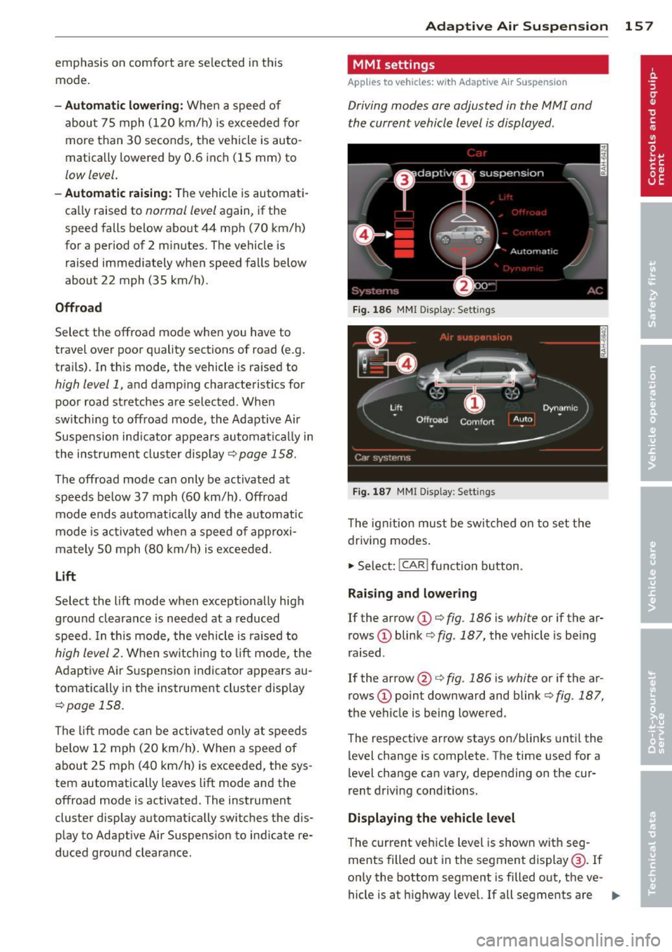
Driving modes are adjusted in the MMI and
the current vehicle level is displayed .
Fig. 186 MMI Display: Sett ings
Fig. 187 MMI Display: Sett ings
Th e ign ition must be switched on to set the
driving modes.
1-Select: !CAR ! function button .
Raising and lowering
If the arrow (D ¢ fig. 186 is white or if the ar
rows
(D blink ¢ fig. 187, the vehicle is being
raised .
If the arrow @i=>
fig. 186 is white or if the ar
rows
(D point downward and blink ¢ fig. 187,
the vehicle is being lowered .
The respective arrow stays on/blinks until the
level change is complete . The time used for a
level change can vary, depending on the cur
rent driving conditions .
Displaying the vehicle level
The c urrent vehicle level is shown with seg
ments filled out in the segment display@. If
only the bottom segment is filled o ut, the ve-
hicle is at highway level. If all segments are
IJJ>-
Page 160 of 340
158 Adapti ve Air Suspens ion
fi lled out, the vehicle is at high level 2 and has
the greatest amount of ground clearance pos
sib le.
While the vehicle is being raised or lowered,
the target level is indicated by an arrow@
c::> fig. 186 or a white border @ c::> fig. 187 . The
arrow/border disappears aga in when the vehi
cle is at the target level.
Limitations to MMI s etting s
Please note that not eve ry dr iving mode can
be selected in every d riving situation . For ex
ample, it is not possible to switch to "lift"
mode at speeds above 12 mph (20 km/h) .
This mode is then shown
greyed out in the
MMI Display.
The vehicle can only be lowered when
all of
the vehicle's doors are closed. If one door is
open, all driving modes whose level sett ing is
belo w the current vehicle level appear
greyed
out
i n the MMI Display. If a door is opened
while the veh icle is being lowered, the lower
ing p rocess is interrupted u ntil all doors are
closed again .
If the system is temporar ily unava ilable due
to, for instance, an empty compressed air
tank, the driving modes that cannot be set ap pear
greyed out in the MM I Disp lay. As soon
as the system is available again, the driv ing
modes can once more be selected in the dis
p lay .
(D} Tips
- Fo r addition al in forma tion on the driv ing
modes
c:;> page 155, Chassis controls.
- When the compressed air tank is empty,
the compressor c an be switched on by
starting the engine . The Adaptive Air
Suspension is once again available, after
waiting a few minutes .
- To prevent over load, the system switches
off tempera rily if seve ral adj ustments
are made in a row. The Adaptive Air Sus
pension is once again available, after
waiting a few minutes. Appearance in the instrument cluster
display
Applies to veh
icles: w ith Adapt ive A ir Suspens ion
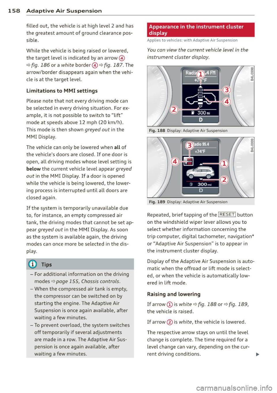
You can view th e current vehicle l evel in the
instrument cluster display.
Fi g. 1 88 Display: Adaptive Air Suspension
F ig . 1 89 Display: Adaptive Air Suspension
Repeated, brief tapping of the I RESET ! button
on the windshield wiper lever allows you to
se lect whether information concerning the
trip computer, digital tachometer, nav igat ion*
or "Adapt ive A ir Suspension" is to appear in
t h e instrument cluster d isp lay .
Display of the Adaptive A ir S uspension is auto
matic when the offroad or lift mode is select
ed, or when the vehicle is automatically low
ered in lift mode.
Rai sing and lowe ring
If arrow
(J) is white c::> fig. 188 or c::> fig . 189,
the vehicle is raised.
If arrow @is
white, the vehicle is lowered .
The respective arrow stays on until the level ch ange is complete. The time requ ired fo r a
level change can vary, depending on the cur-
ren t drivi ng conditions . ..,_
Page 161 of 340

Displaying the vehicle level
The current vehicle level is shown with seg
ments filled out in the segment display @. If
only the bottom segment is filled out, the ve
hicle is at highway level. If all segments are
filled out, the vehicle is at high level 2 and has
the greatest amount of ground clearance pos
sible.
While the vehicle is being raised or lowered,
the target level is indicated by an arrow @
¢
fig. 188 or a white border @¢ fig. 189. The
arrow/border disappears again when the vehi
cle is at the target level.
Jacking mode when changing a flat tire
Applies to vehicles: with Adaptive Air Suspension
This mode must be activated in the MMI be
fore raising the vehicle with a jack or on a ve
hicle lift.
.,. Select: ICARI function button> !SETUP I func
tion button >
Jacking mode. Or
.,. Select:
I CARI function button > Car systems*
control button > Servicing & checks> Air
susp.: tire change.
The vehicle jack mode must be activated be
fore changing a wheel so that the automatic
control processes for the air suspension do not make lifting with the vehicle jack more dif
ficult.
The check lamp
II in the instrument cluster
display illuminates in vehicle jack mode.
0) Tips
The vehicle jack mode is switched off auto
matically at speeds above 9 mph (15 km/
h).
Towing a trailer
Appl ies to vehicles: with towing hitch and Adaptive Air
Suspension
Automatic lowering is not desirable when
towing a trailer.
.,. Select: ICAR I function button> !SETUP I func
tion button >
Towing mode. Or
Adaptive Air Suspension 159
.,. Select: !CAR I function button > Car systems*
control button > Vehicle settings > Air
susp.: towing.
As long as towing mode is activated, a vehicle
with a trailer appears in the
adaptive air sus
pension
main menu.
Level Adjustment when towing a trailer
- Before hitching up the trailer and before ad
justing the tongue weight at the trailer, the
automatic or comfort mode
must be select
ed so that the vehicle can be at normal level
¢page 157, MMI settings.
-If driving in dynamic mode is desired, this
mode
must be selected before hitching up
the trailer and before adjusting the tongue
weight. However, note that your vehicle is lowered and ground clearance is reduced.
- If you have to drive under difficult road con
ditions, you can select offroad or lift mode,
after hitching up the trailer or after adjust
ing the tongue weight.
- If the vehicle is at
normal level, and you se
lect offroad mode while traveling at speeds
higher than 22 mph (35 km/h), the vehicle
will not be raised. Offroad mode will appear as the active mode in the MMI Display.
- If the vehicle is in offroad mode at
high level
1 ,
it automatically lowers to normal level
when the vehicle is traveling at speeds ex
ceeding approximately 31 mph (SO km/h) .
The vehicle is automatically raised to
high
level 1
again when the traveling speed falls
below approximately 25 mph (40 km/h).
Restrictions when operating with a trailer
When operating with a trailer, the lift mode
can only be selected up to about 12 mph (20
km/h). Lift mode is automatically canceled
again when a speed of about 25 mph (40 km/
h) is exceeded.
If the vehicle is in automatic, comfort, offroad
or lift mode before the trailer towing mode is
activated, the dynamic mode cannot be acti
vated .
If the vehicle is in dynamic mode before tow-
ing operation is activated, it can be driven in
IJI,-
Page 162 of 340
160 Adapti ve Air Su spen sion
this mode. If the suspension is switched from
this mode to another mode, dynamic mode
cannot be re-selected .
(D Tips
-For vehicles with a factory installed tow
ing hitch or a trailer hitch that was in
stalled later accord ing to factory specifi
cations, the system recognizes "Trailer
tow ing mode" and activates this specia l
mode automatically, as soon as the elec
trical connection on the trailer socket is
connected. The mode ceases a utomat i
ca lly when the elect rical connection to
t h e trai ler socket is d isconnected.
- If the tra iler towing mode has been acti
vated, the vehicle will not drop to the
l ow or highway level.
Cargo mode
Applies to vehicles: with Adapt ive Air Suspe nsio n
The rear of the vehicle can be lowered to
make it easier to load.
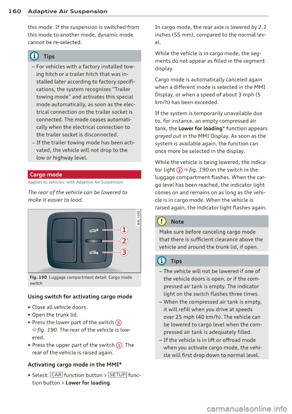
Fig. 190 Luggage compa rtment detail: Cargo mode
sw itch
Using switch for activating c argo mode
.. Close all vehicle doors .
.. Open the trunk lid .
.,. Press the lower pa rt of the switch @
<=> fig. 190. The rea r of the vehicle is low
ered.
.,. Press the uppe r part o f the switch @. T he
rear of the vehicle is raised again.
Activating cargo mode in the MMI*
.. Select: ICAR I funct io n button> !SETUP I func
t ion button >
Lower for loading .
In cargo mode, the rear ax le is lowered by 2 .2
inches (S5 mm), compared to the normal lev
el.
While the veh icle is in ca rgo mode, the seg
ments do not appear as filled in the segment
display.
Cargo mode i s automatic ally c an ce le d again
when a different mode is selected in the MM I
Display, or when a speed of about 3 mph (5
km/ h) has been exceeded.
If the system is tempora rily unavailable due
to, for instance, an empty compressed air
tank, the
Lower for loading * function appears
greyed out in the MMI Display. As soon as the
system is available again, the funct ion can
once more be selected in the disp lay.
While the vehicle is being lowered, the indica
tor light @~
fig. 190 on the switch in the
l uggage compartment flashes. When the car
go leve l has been reached, the indicator light
comes on and remains on as long as the vehi
cle is in cargo mode. When the vehicle is
r aised agai n, the indicator light flashes again.
(D Note
M ake sure before canceling cargo mode
that there is sufficient clearance above the
vehicle and around the trunk lid, if open.
(D Tips
- The vehicle w ill not be lowered if one of
the vehicle doors is open, or if the com
pressed air tank is empty. The indicator
light on the switch flashes three times.
- Whe n the compressed air tank is empty,
it will refill when you drive at speeds
over 25 mph (40 km/ h). The vehicle can
be lowered to cargo level whe n the com
pres sed air tan k is adequately filled.
- If the vehicle is i n lift or off road mode
when you act ivate cargo mode, the vehi
cle will fi rst drop down to no rma l level.
Page 165 of 340
Reprogramming the buttons
"' Switch on the ignition (do not start the en
gine).
"'To reprogram an individual button, press
and hold the button until the LED@starts
to flash quickly (after about ten seconds).
Release the button immediately. The Home
Link module will now remain in learning
mode for 5 minutes.
"'Continue with step 5 .
@ Tips
- The required distance between the hand
transmitter and the Homelink module in
the bumper ¢
fig. 192 depends on the
system that you are programming .
- Depending on the model of the garage
door opener, you may need to release the
button on the remote and press it again
when programming. When program
ming a new device, keep the button
pressed for at least 15 seconds before
trying again with the transmitter in a dif
ferent position. Watch out for the emer
gency flasher during that time.
Programming the rolling code
App lies to vehicles: with Home link
Additionally, a rolling code programming for
the Homelink universal remo te control is re
quired for some systems.
Identifying the rolling code
"'Press the previously programmed Homelink
button again and hold it down .
"' Look at the LE D @ ¢
page 161, fig. 191 . If
the LED blinks quickly, the features, such as
the garage door opener, are equipped wi th
the rolling code .
"'Program the rolling code as follows:
Activating the garage door opener motor
unit "'Locate the setting button on the garage
door opener motor unit . The exact location
and color of the button may vary depending
on the garage door opener manufacturer .
Homelink 163
"' Press the setting button on the garage door
opener motor unit (usually this will activate
a "setting light display" on the motor unit).
Now you will have about 30 seconds time to
perform the Homelink button programming
on the controls .
Programming on the controls
"'Press the Home link button that was already
programmed and hold for two seconds.
"'To end rolling code programming, press and
hold the Homelink button for two seconds
again.
"'The Homelink button may need to be press
ed a third time to end the adjustment proce
dure for some garage door openers .
After the controls have been programmed, the
garage door opener should recognize the HomeLink signal and operate when the Home
Link button is pressed. Now you may program
the other buttons as needed.
@ Tips
- Programming the rolling code can be
performed quicker and more easily with
the help of a second person.
- If difficulties should arise when pro
gramming the rolling code, consult the
operating instructions for the garage
door opener or other devices for possible
solutions.
Page 188 of 340
186 Airbag sys tem
as def ined in the electronic control unit
Q page 194, PASSENGER AIR BAG OFF light.
A lways remember, a ch ild safety seat or infant
carrier insta lled on the front sea t may be
struck and knocked o ut o f position by the rap
id ly inflating passeng er's airbag in a frontal
coll is ion . T he airbag cou ld greatly reduce the
effec tiveness of the child restraint and even
serious ly injure the child during inflat ion.
F or this reason, and because the back seat is
the safest p lace for children - when properly
restra ined acco rd ing to their age and si ze - we
s trongly recommend that children always sit
in the back seat
Q page 204, Child Safety .
A WARNING
A child in a rearward-facing child safety
s e at insta lled on the front passenger seat
w ill be seriously injured and can be k illed if
t he fr ont a irbag inflates - even with an Ad
vanced Airbag System.
- T he i nflating a irbag will hit the child
safety seat or infant carrier wit h great
f orce and w ill smash the ch ild safety sea t
and child against the backrest , center
armrest, door or roof.
- Always insta ll rear -facing child sa fety
seats on the rear seat.
- If you mus t install a rearward facing
child safety seat on the front passenger
seat because of exceptional circ umstan
ces and the
PASSENG ER AIR BAG OFF
light does not come on and stay on , im
med iately install the rea r-facing child
safety seat in a rear seating position and
hav e the a irbag system inspected by you r
authori zed Aud i dealer.
- Forward-fac ing ch ild safety seats instal
led on the front passenger's seat may i n
terfere wi th the deployment of the air
b ag and cau se serious person al injury to
the ch ild .
A WARNING
If, in exceptional c ircumstances, you must
install a forward-facing child restra int on
the front passenger's seat: -
Always make sure the forward-facing
seat has been designed and certified by
its manufacturer for use on a front seat
with a passenger front and s ide a irbag .
- Never put the forward-facing child re
straint up against or very near the instru ment panel.
- Always move the passenger seat into its
rearmost pos ition in the seat's fore a nd
aft ad justment range, as fa r away from
the airbag as possible b efore installing
the forwa rd-fa cing ch ild restra int. The
b ackrest mus t be a djusted to a n up right
position.
- Make s ure that the
PASSENGER AIR BAG
OFF
li ght comes on and stays o n all the
t ime wheneve r the ignition is switched
on.
A WARNING -ra----
To reduce the risk of serious injury, make
sure that the
PASSENGER AIR BAG OFF
light will be displayed whenever a child re
straint is installed on the front passenger
seat and the ignition is sw itched on.
- If the
PASSENGER AIR BAG OFF light
does not stay on, perform the checks de
scribed
Q page 194, Monitoring the Ad
vanced Airbag System .
-Take t he chi ld restraint off the front pas
senger seat and install it prope rly at one
of the rear seat positions if t he
PASSEN
GER AIR BAG OFF
li ght does not stay on.
- Have the airbag system inspected by
your author ized Audi deal er immed iate
ly .
- Always carefu lly follow instr uctions from
chi ld restraint manufacture rs when in
st all ing c hild restra ints .
A WARNING
If, in exce ptiona l circumstances, you m ust
i nsta ll a forward or rearw ard-fa cing child
r estra int on the front passenger's seat :
- Imp roper ins tallation o f child restra ints
can reduce their effec tiveness or even
Page 198 of 340
196 Airbag sys te m
- accessory seat covers or cushions or other
things that may cause an incorrect reading
or impress ion on the weight-sens ing mat
under the upholstery of the seat have been
removed from the front passenger seat,
- a safety belt extender has not been left in
the safety belt latch for the front passenger
seat.
In addition to the
PA SSENGER AIR B AG OFF
light in the center of the instrument panel,
the message
PASS ENGER AIR B AG O FF or
PASS ENGER AIR B AG O N will briefly appear
in the instrument cluster display . T his is to in
form the driver of the current front passenger
a irbag status .
Important safety instructions on
monitoring the Advanced Airbag System
_&. WARNING
An airbag system that is not functioning
prope rly cannot provide supplemental pro
tect ion in a frontal crash.
- If the airbag indicator light
c::> page 16
comes when the vehicle is be ing used,
have the system inspected immediately
by you r authorized Aud i dea ler.
It is pos
sible that the airbag will inflate when it
is not supposed to, or w ill not inflate
when it should .
_&. WARNING
If the front airbag inflates, a child witho ut
a child restraint, or in a rearward-facing
child safety seat, or in a forward-facing
child restraint that has not been properly
installed will be seriously injured and can
be killed .
- Even though your veh icle is equipped
with an Advanced Airbag System, make certain that all children, especially 12
years and younger, a lways ride on the
back seat properly restrained for their
age and size.
- Always install forwa rd or rear-facing
child safety seats on the rear seat -even
with an Advanced Airbag System. -
If you must install a rearward-facing
child safety seat on the front passenger
seat because of exceptional c ircumstan
ces and the
PA SS ENGER AIR BA G OFF
light does not appear and stay on, imme
diate ly install the rear-facing child safety
seat in a rear seat ing pos ition and have
the airbag system inspected by your au
thorized A udi dealer.
- A tight tether or other strap on a rear ward-facing child restraint attached to the front passenger seat can p ut too
m uch pressure on the weight-sensing
mat in the seat and register more weight
than is actually on the seat. The heavier
weight registered can make the system
work as though an adult were on the seat
and deploy the Advanced Airbag when it
must be suppressed causing ser ious or
even fata l injury to the ch ild.
- If, in exceptional circumstances, you
must install a forward-fac ing ch ild re
straint on the front passenger seat, al
ways move the seat into its rearmos t po
sition in the seat's fore and aft adjust
ment range, as far away from the airbag
as possible. The backrest must be adjust
ed to an upright position. Make sure that
the
PASSEN GER AIR BAG OFF light
comes on and stays on all the time when
ever the ignit ion is switched on .
_&. WARNING
r-
- If the PASSENGER AIR BAG OFF light
does not go out when an adult is sitting
on the front passenger seat after taking
the steps described above, make sure the
adu lt is properly seated and restra ined at
one of the rea r seat ing pos itions.
- Have the airbag system inspected by
your author ized Audi dealer befo re trans
port ing anyone on the front passenger
seat.
('D Tips
If t he weight-sensing mat in the front pas
senger seat de tects an empty seat, the
front airbag on the passenger side wi ll be
jll,,
Page 231 of 340
Replacing wh eels/ tire s
Vehicles w ith all-wheel drive must a lways
have tires of the same size. Also avoid tires
with different tread depths. For details see
page ¢
page 284, New tires and replacing
tires and wheels .
.&_ WARNING
Always adjust your driving to road and traf
fic conditions . Do not let the extra safety
afforded by all-wheel dr ive tempt you into
tak ing extra risks.
-Although the all-wheel dr ive is very ef
fective, always remember that braking
capacity is limited by t ire traction . You
sho uld therefore not dr ive at excessive
speeds on icy or s lippery road surfaces.
- On wet road su rfaces, be careful not to
dr ive too fast because t he front wheels
cou ld beg in to s lide on top of the wa ter
(aquaplaning). If this sho uld occ ur, you
w ill have no warning from a sudden in
crease in engine speed as with a front
whee l drive vehicle. A lways drive at
speeds wh ich are suited to the road con
ditions -risk of c rash.
Energy management
Starting ability is optimized
Energy management controls the distribution
of electrical energy and thus optimizes the
availability of electrical energy for starting
the engine.
I f a vehicle w it h a conventional energy system
i s not driven for a long pe riod of time, the bat
tery is disch arged by idling c urrent cons umers
(e .g. immobilizer) . In ce rtain c ircumstances it
can result in there being insufficient energy
ava ilab le to start the engine .
I n tell igen t energy management in your vehi
cle hand les the d istribution of electrical ener
gy . Starting abi lity is marked ly imp roved and
the life of the battery is extended.
Int ellig ent technolog y 229
Basica lly, energy management consis ts of
batte ry diagnosi s, idling cur rent manage
ment
and dynamic energy management.
Battery diagnosis
B attery diagnosis continuously de termines
the state of the battery . Sensors determine
batte ry voltage, battery current and battery
temperature . This determines the current
state of charge and the power of the battery.
Idling current management
Id lin g cur ren t man agement reduces energy
consumption while the vehi cle is standing.
With the ig nition switched off, it controls the
energy supply to the various electrical compo nents. Data from battery diagnos is is cons id
ered.
Depend ing on the battery's state of cha rge,
individual cons umers are gradually turned off
to prevent excessive discharge of the battery
and thus maintain starting capability.
Dynamic energy manag ement
While the vehicle is being driven, dynamic en
ergy management distrib utes the energy ge n
erated according to the needs of the individ u
al components. It regulates consumption, so
that more electrical energy is not being used
than is be ing generated and ensures an opti
mal state of charge for the battery .
(D Tips
-But even e nergy management cannot
negate the limits of physics. Consider
t hat the powe r and l ife of a bat tery are
l imited.
- If start ing ability is threatened, you are
informed by a warning ¢
page 230,
Driver notification in the instrument
cluster display.
•
•