cruise control AUDI R8 SPYDER 2011 Owners Manual
[x] Cancel search | Manufacturer: AUDI, Model Year: 2011, Model line: R8 SPYDER, Model: AUDI R8 SPYDER 2011Pages: 244, PDF Size: 59.74 MB
Page 11 of 244
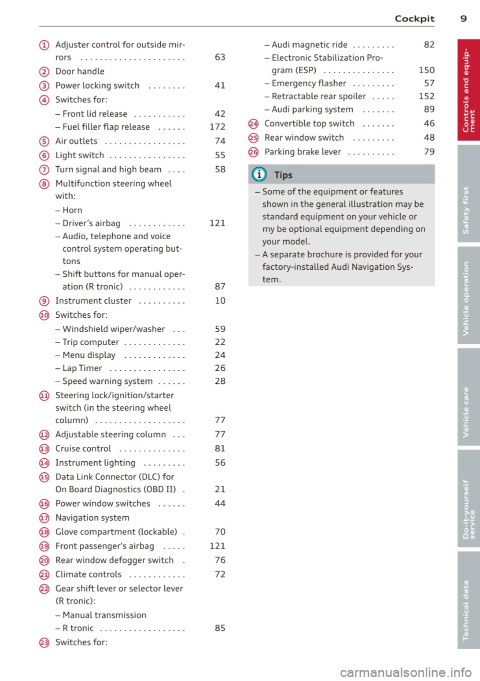
(!) Adjuste r control for outside m ir-
rors .... ..... ..... ... ... . .
@ Door handle
@ Power locking sw itch
© Switches for:
- Front lid release .......... .
- Fuel filler flap release . .. .. .
® A ir outle ts ............ .... .
® Light switch ........... .... .
0 Turn signal and high beam . .. .
@ Mul tifunction steering wheel
with:
- Horn
- Driver's airbag ....... .. .. .
- Audio, telephone and voice
control system operat ing but
tons
- Shift buttons for manual oper- at ion (R tronic) ....... .. .. .
63
4 1
4 2
172
74
55
58
121
87
® I nstrument cluste r . . . . . . . . . . 10
@ Switches for:
- Windsh ield wiper/washer . . . 59
- Trip computer . . . . . . . . . . . . .
22
- Menu disp lay . . . . . . . . . . . . . 24
- Lap Timer . . . . . . . . . . . . . . . . 26
- Speed wa rning sys tem . . . . . . 28
@ Steering lock/ignition/starter
switch (in the steering wheel
column) . . . . . . . . . . . . . . . . . . . 77
@ Adjustable s teer ing column . . . 77
@ Cruise control . . . . . . . . . . . . . . 81
@ Instrument lighting . . . . . . . . . 56
@) Data Link Connector (DLC) for
On Board Diagnostics (OBD II) . 21
@) Power wi ndow switches . . . . . . 44
@ Navig ation system
@ Glove compartment ( lockable) . 70
@ Fro nt passenge r's a irbag . . . . . 121
@ Rear window defogger sw itch . 7 6
@ Climate con trols . . . . . . . . . . . . 72
@ Gear shi ft leve r or selector lever
(R troni c):
- Manua l transm ission
- R tronic . . . . . . . . . . . . . . . . . . 85
@ Sw itches for:
Cockpi t 9
-Audi magnetic ride . ..... .. . 82
- Elect ron ic Stabiliza tion P ro -
gram (ES P) . . . . . . . . . . . . . . . 150
- E mergency flasher . . . . . . . . . 57
- Ret ractable rear spo iler . . . . . 152
- Aud i parking system . . . . . . . 89
@ Convertib le top switch . . . . . . . 46
@ Rear window switch . . . . . . . . . 48
@ Pa rking brake lever . . . . . . . . . . 79
(D Tips
- Some of the equipment or features
shown in the genera l ill ustration may be
standard equ ipment on your vehicle or
my be op tional eq uipme nt depending on
yo ur mode l.
- A separate brochure is p rov ided for yo ur
fac to ry-i nstalled Audi Nav iga tion Sys
t em .
Page 16 of 244
14 Instruments and warning /indicator light s
Warning/indicator lights
Overview
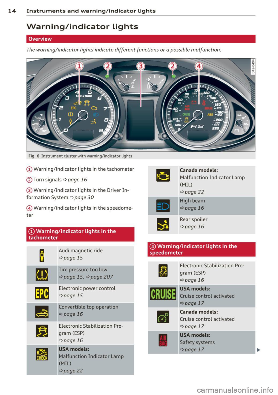
The warning/indicator lights indicate different functions or a possible malfunction.
Fig. 6 Instrument duster w ith warning/indicator lights
(D Warning/ind icator lights in the tachometer
@ Turn signals
c::> page 16
® Warning/indicator lights in the Driver In
formation System
c::> page 30
@ Wa rning/ind icator lights in the speedome
ter
@Warning/indicator lights in the
tachometer
Audi magnet ic r ide
<::>page 15
Tire pressure too low
<::>page 15, c::>page207
Electronic power control
<::>page 15
Convertib le top operation
r::!>page 16
Electronic Stabilizat io n Pro
gram (ESP)
c:>page 16
USA models:
Malfunction Indicator Lamp
( M IL)
¢page22
Canada models :
Malfunction Indicator Lamp
(MIL)
c:>page22
High beam
<::>page 16
Rear spoiler
c:>page 16
@ Warning/indicator lights in the
speedometer
I
•
Elec tron ic Sta biliza tion Pro
gram (ESP)
<::>page 16
USA models:
Cruise control activated
<::>page 17
Canada models :
Cruise control activated
c::> page 17
USA models:
Safety systems
<::>page 17
-----·-
Page 19 of 244
Instrument s and warnin g/indi cator ligh ts 17
CRUISE /vJ' Cru ise control
The warning/indicator light (ij ;jl)~1~ (USA mod
e ls)/ . (Canasda models) illum inates when
the cruise cont rol is activated.
I I ! .!r Safety systems
This warning/indicator light monitors the air
bag and the pretensioner systems.
The warning light I (USA models) ;II (Cana
da models) illuminates for a few seco nds eac h
time you switch on the ignition.
If the
I (USA models)/ . (Canada models)
warn ing light does not go out, or if it illumi
nates wh ile you are driv ing, or if it starts to
b link, then there is a ma lf u nction somewhere
in the system. If the light does not ill uminate
when you switch on the ignition, this also
means there is a ma lfunction.
A WARNING
If you have a malfunction in the airbag sys
tem, contact your authorized Audi dealer
immediately. Otherw ise the airbag or the
belt pretensioner may not work proper ly in
an acc ident.
D Generator
This warning/indicator light detects a mal
function in the generator or in the vehicle's
electrical system.
The . warning/indicator lig ht illuminates
when you switc h on t he ignit ion and must go
out after the engine has started.
If the . warning/indicator light i lluminates
while you are driving, you should contact your author ized Audi dealer. Since the vehicle bat
tery is discharging, you should switch off any
u nnecessary electrical consumers (for exam
p le, the air conditioner).
Q) Note
If the . warn ing/ indicator light (mal
function in the engine cooling system) in
the instrument cluste r shou ld i llum inate ¢
page 32, stop the veh
icle and t urn off
the engine. The coolant pump is not work i ng -this can cause engine damage!
4 Safety belt warning light
The warning light is a reminder to fasten
safety belts.
T he warning light . comes on fo r a few sec
onds after the ignition is switched on as a re
minder to fasten yo ur safety be lt. Additional
l y, an acoustic warning (gong) will a lso sound.
Addi tional in format ion on safety belts
¢ page 109 .
BRAKE/((D) Brake system
This warning/indicator light flashes when the
broke fluid level is too low or when there is a
malfunction in the ABS .
If the wa rning/ind icator light flas hes 111111111;
• (with the parking brake re leased), stop the
vehicle and obtain qualified help¢&, .
If the ABS fails, the ABS wa rn ing/ indicator
l igh t
r.m!J,11] illumina tes along w ith the
brake sys tem warning/ ind icator light- /
. ¢&, .
(USA mode ls): If the war ning light - and
the warn ing light
Lil ill umin ate together, im
med iate ly contact yo ur a uthorized Aud i dea le r
or qualified workshop to have all brake pads inspected ¢
page 33.
When the light comes on, an aud ible warning
s ignal is also g iven.
Parking brake set
The _ /. warning/ind icator light illumi
nates when the parking brake is set¢&, . The
fo llow ing message appears in the d isplay:
Handbrake i s app lie d . If yo u inadvertent ly
drive off with the parking brake applied, a
buzzer (warning tone) sounds.
Page 83 of 244
Cruise control
Introduction
The cruise control system keeps the speed
constant .
The cruise control system makes it possible to
drive at a constant speed over 20 mph (US
model) or 30 km/h (Canadian model). This is
true only to the extent that engine power or
engine braking effect allow . Using the system
takes the strain off the "gas peda l foot" -es
pec ial ly on long tr ips.
In the control mode, the indicator light in the
instrument cluster is lit
(Dj;(i )~i~ (US model) ,111
(Canadian model).
The cruise control system automatically
switches itself off imm ed iately under the fol
lowing cond itions:
- Pressing the brake pedal.
- Pressing the clutch pedal.
A WARNING
-Always pay attention to traffic even when
the cruise control system is switched on.
You are always responsible for your
speed and the distance between your ve hicle and other vehicles.
- For safety reasons, the cruise control sys tem shou ld not be used in the city, in
stop-and-go traffic, on twisting roads
and when road conditions are poo r (such
as ice, fog, gravel, heavy rain and hydro
planing) -risk of accident.
- Turn off the cr uise control system tem
porarily when entering turn lanes, high
way exit lanes or in construction zones.
- Please note that inadvertently "rest ing"
your foot on the accelerator peda l causes
the cruise control system not to brake .
This is because the cruise contro l system
is overridden by the driver's acceleration.
(D Note
On manual transmission vehicles: If you
shift into neutral with the cruise contro l
On th e road 81
system switched on, always depress the
clutch pedal! Otherwise the engine will
race and could be damaged as a result .
(D Tips
When driving on steep downward grades,
the cruise control system cannot keep the
speed constant. The vehicle's own weight
increases the speed. Shift into a lower gear
i n plenty of t ime or brake the vehicle with
the foot brake .
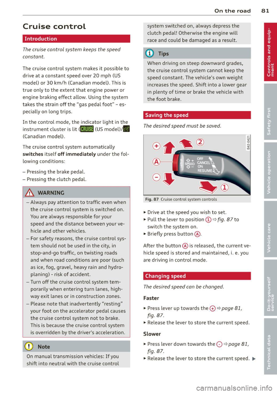
Saving the speed
The desired speed must be saved.
Fig. 87 C ruise control system controls
.,. Dr ive at the speed you w ish to set.
.,. Pull the lever to position
(D c:> fig. 87 to
sw itch the system on.
.,. Briefly press button @.
After the button @is released, the current ve
hicle speed is sto red and maintai ned, i.e. you
are driv ing in control mode.
Changing speed
The desired speed can be changed.
Fas ter
.,. Press lever up towards the 0 c:> page 81,
fig. 87.
.,. Release the lever to store the current speed .
Slower
.. Press lever down towards the O c:> page 81,
fig. 87.
.,. Release the lever to store the current speed. IJJl-
Page 84 of 244
82 On the road
You can also increase your speed by pressing
the accelerator pedal. After you release the
accelerator pedal, the system automat ically
adjusts back down to the speed you previously
set .
However, if you exceed this speed by 5 mph
(10 km/h) for longer than 5 m inutes, the stor
ed speed will be deleted. You will have to re
save it.
Briefly pressing lever
The desired speed is increased by about 2 mph
(2 km/h) by briefly pressing the lever upwards
towards
c:> page 81 , fig . 87 0 -
The desired speed is decreased by about 2
mph (2 km/h) by briefly pressing the lever
downwards towards
c:> poge 81, fig. 87G).
Switching control mode off temporarily
.. Step on the brake pedal, or
.. Depress the clutch pedal all the way, or
.. Press the lever towards @(not latched)
c> page 81, fig. 87 .
When the system is turned off temporarily,
the speed stored at the time is retained.
To resume the stored speed, release the brake
or clutch pedal and pu ll the lever to position
(D .
If no desired speed was stored when the sys
tem was temporarily switched
off, you can
store a new desired speed as follows: Drive at
the desired speed and briefly press button
c> page 81, fig. 87 @ (SET) .
A WARNING
You should only return to the saved speed
if it is not too fast for the current traffic
conditions - risk of an accident!
Deactivating
.. Press leve r into position @(latc hed)
¢ page 81, fig. 87.
The saved speed value is deleted when the ig
nition is switched
off.
(D Tips
Switch the cruise control system off com
pletely at the end of each trip. When you
start the next trip, the desired speed can
be set simp ly from the basic setting
c>poge 81.
Audi magnetic ride
Damping con be adjusted to the driver's pref
erence and it adapts automatically to the cur
rent driving situation .
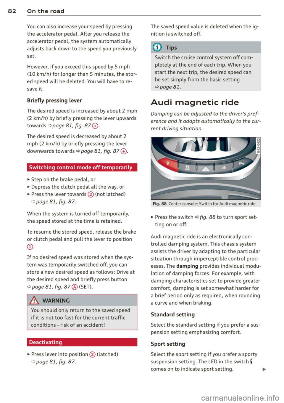
Fig. 88 Center console: Sw itch for Audi magnet ic ride
.. Press the switch c:> fig. 88 to turn sport set-
ting on or
off.
Audi magnet ic rid e is an elec tronically con
trolled damping system . This chassis system
assists the driver by adapting to the particular
situation through imperceptible control proc
esses. The
damping provides individual modu
lation of damp ing forces. For examp le, w ith
damp ing characteristics set to provide greater
comfort, damping is set somewhat harder for
a brief period only as required, when rounding
a curve and when braking.
Standard setting
Select the standard setting if you prefer a sus
pension setting emphasiz ing comfort.
Sport setting
Select the sport setting i f you prefer a spo rty
suspension setting . The LED in the switch
g
comes on to indicate sport setting .
Page 234 of 244
232 Index
Controls and displays ........... .... .. . 8
Convenience close/open feature .. .. ....
40
Convertible child safety seats .. .. ..... 144
Conve rtible locking retractor
Activating . . . . . . . . . . . . . . . . . . . . . . . .
148
Deactivating . . . . . . . . . . . . . . . . . . . . . . 149
Using to secure a child safety seat l46, 148
Convertible top
Emergency operation .... .. .. .. .. .. . .
49
Error message ............ ... .... .. 47
General information ....... ..... .. . .
46
Indicator light ............ ... .... .. 16
Malfunction ............... .. .... .. 4 7
Opening/closing .......... .. .. .. .. ..
46
Retracting/ex tending rear window . .... 48
Wind deflector ............... .. ... . 48
Coolant system ..................... 181
Adding coolant ............. .. .... . 183
Checking the engine coolant level .....
182
Cruise control .............. ... .... .. 81
Changing speed .................... 81
Deactivating . . . . . . . . . . . . . . . . . . . . . . .
82
Driving in control mode .... .. .. .. .. . . 81
Switching off temporarily .. .. .. .. .. . . 82
Warning/indicator light .... .. .. .. .. .. 17
Cup holder . . . . . . . . . . . . . . . . . . . . . . . . . . 68
Current fuel mileage . . . . . . . . . . . . . . . . . 23
D
Damping
refer to Audi magnetic ride ..... .. .... 82
Data . ... .. .. ................ ..... . 228
Data recorder ............. .. .. .... . 150
Date display . . . . . . . . . . . . . . . . . . . . . . . . 11
Daytime running lights ....... ... .... .. 55
Declaration of compliance
Cell phone package ..... .. .. .. .. .. .
212
Electronic immobilize r ..... .. .. .. .. . 212
H omelink ® universal remote control .. 212
Remote control key ........ ... .... . 212
Tire pressure monitoring system . ... . 212
def . .. .. .. ............... .... .... .. 12
Defective light bulb wa rning . .. .. .... .. 35
Defrosting the windows ...............
75
Determining correct load limit ..... .. . 197
Digita l compass ........... .. .. .... .. 64
Dimensions ..... .. ............. .... 229
Dipst ick ... .... ... .. .............. . 180
Distance ..... .. .. .. ........... .... . 23
Doors Emergency locking ................ ..
42
Driver information ...... ........... .. 31
Driver informat ion system
Menu button . . . . . . . . . . . . . . . . . . . . . . 25
Menu display . . . . . . . . . . . . . . . . . . . . . .
24
Open door or front lid warning ........ 20
Outside temperature display . . . . . . . . . . 20
Red symbols . .. .. .......... ...... .. 30
Serv ice interval display ......... .. .. .
21
Setting ... .... .. .. ........... .... . 25
Sound system display . . . . . . . . . . . . . . .
20
Trip computer .... ............. ..... 22
Yellow symbo ls . . . . . . . . . . . . . . . . . . . . 30
Driver seat
refer to Seating position . . . . . . . 100, 101
Driving safely . . . . . . . . . . . . . . . . . . . . . . . 99
Driving through water .............. . 158
Dry sump lubrication .... ..... ... .. .. 157
Duplicate key . . . . . . . . . . . . . . . . . . . . . . . 3 7
Dust filter . . . . . . . . . . . . . . . . . . . . . . . . . . 73
E
Elapsed time .... .. ............. .... . 23
Electrical voltage .. ............. .... . 13
Electronic differential lock (EDL) ....... 150
Warning/indicator light ............ ..
18
Electronic immob ilizer . . . . . . . . . . . . 12, 38
Electronic power control ( EPC) . . . . . . . . . 15
Electronic Stabilization Program ....... 150
Electronic stabilization program (ESP)
Warning/indicator lights .............
16
Emergency flasher . ............. .... . 57
Warning/indicator lights ........ .. .. . 16
Emergency key . . . . . . . . . . . . . . . . . . . . . . 3 7
Emergency locking ........ ...... .. .. .
42
Emergency operation
Convertible top .. ... .......... .. .. .
49
Emergency release
Front lid . . . . . . . . . . . . . . . . . . . . . . . . . . 43
Emergency starting ................ .
219
Emergency towing . ............... .. 222
Page 240 of 244
238 Index
Tire pressure monitoring system ...... . 206
Loss of air pressure . . . . . . . . . . . . . . . . . 34
Malfunctions . . . . . . . . . . . . . . . . . . . . . . 34
Sensors .. ............... .. .. .... . 201
Tires and wheels ......... .... .... . 201
Valves ... .. ................ ... ... 201
Warning/ indicator light .... .. .. .. .. . . 15
Tire repair kit .............. ... .... . 213
T ires .. .. ...... ........... .. .. .... . 189
Pressure ... ............. .... .. .. . 206
Replacing . . . . . . . . . . . . . . . . . . . 199, 201
Service life ............... ... .... . 198
Speed rating letter code ........... . 200
Tire manufacturing date ... .. .. .. .. . 200
Tire pressure monitoring system ..... 206
Tire specifications ......... ... .. .. . 200
Tread depth .. .. ...... .... ... .. .. . 198
Uniform tire quality grading .. .. .. ... 203
W inter t ires ............. .. .. .. .. . 203
Tires/Wheels Low aspect ratio t ires .... .. .. .. .... . 205
Tires and vehicle load limits ... ..... .. . 196
Tires and wheels Check ing tire pressure ......... .. ... 195
Cold t ire inflation pressure . .. .. .. .. . 193
Dimensions ............... ... .... . 199
General notes .............. .. .... . 189
Glossary of tire and loading termino lo-
gy .. .. .. ................. .. .... . 190
New tires and wheels ...... .. .. .... . 199
Replacing ............... ........ . 200
Snow chains .............. ... .. ... 204
T ire pressure monitor ing system .. .. . 201
Tires and vehicle load limits .. .. .. .. . 196
Wheel bolts ............. .... .... . 205
W inter t ires .. ........... .. .. .. .. . 203
Tire service life ................ .. .. . 198
Tool kit ..... ................ ..... . 213
Touch-up paint ............ .. .. .. .. . 164
Towing Tow truck procedures ...... .. .. .. .. . 222
T . l owing oop ................. .. .... .
222
Transport Canada ... ..... .. .. .. .. .. . 106
Tread Wear Indicator (TWI) .. .. .. .. .. .
198
Trip computer . . . . . . . . . . . . . . . . . . . . . . . 22
Trip odometer .............. ... .. ... . 12
Turn signals . ................. ..... .. 58 Turn
Signals
Warning/indicator lights ............. 16
u
Unfastening safety belts
Unidirectional tires ........ ...... .. . .
Uniform tire quality grading ....... .. . 114
189
203
Universal Radio-Frequency Remote Control
(HomeLink®) .... .. ............. .... . 95
Unlocking .. ... ... .. .............. .. 40
Power locking system ........... ... . 40
V
Vanity mirror . . . . . . . . . . . . . . . . . . . . . . . . 59
Vehicle-care products ................ 161
Vehicle electrical system . . . . . . . . . . . . . . 17
Vehicle Identification Number (VIN) .. .. 226
Vehicle jack . ...... ............. .... 217
Vehicle literature .. ................ ...
5
Vehicle tool kit .... ................ . 213
Ventilation . . . . . . . . . . . . . . . . . . . . . . . . . 72
Voltmeter display . . . . . . . . . . . . . . . . . . . . 13
w
Warning/indicator lights ......... .... . 10
Airbag system . . . . . . . . . . . . . . . . . . . . . 17
Anti-Lock Brake System . . . . . . . . . . . . . . 18
Audi magnetic ride .............. ... . 15
Brake system . . . . . . . . . . . . . . . . . . . . . . 17
Cruise control . . . . . . . . . . . . . . . . . . . . . . 17
Electronic differential lock (ED L) .. .. .. . 18
Electronic power control (EPC) . . . . . . . . 15
Electronic stabilization program (ESP) .. 16
Generator . . . . . . . . . . . . . . . . . . . . . . . . . 17
High beam . ..... ................ .. 16
Rear spoi ler ..... ............. ..... 16
Safety belts . . . . . . . . . . . . . . . . . . . . . . . 17
Tire pressure monitoring system . .. .. . lS
Turn signals . .. .. ..... ......... ... . 16
Warning lights . . . . . . . . . . . . . . . . . . . . . . 14
Red symbols in the center display . .... . 30
Yellow symbols in the center display .. . 30
Warranty coverages ................ . 209
Washing ...... ... ................ . 161
Folding top cleaning ... .. .. .. .. .. .. 163