start stop button AUDI R8 SPYDER 2012 Owners Manual
[x] Cancel search | Manufacturer: AUDI, Model Year: 2012, Model line: R8 SPYDER, Model: AUDI R8 SPYDER 2012Pages: 236, PDF Size: 59.24 MB
Page 13 of 236
Instrument s and warnin g/indic ator ligh ts 11
Immobilizer
When the ignition is switched on, the data on
the ignition key are scanned automatically.
I f an unautho rized key was used,
SAFE is dis
p layed cont inuously in the odometer display
field. The veh icle cannot be operated
¢ page 33.
Voltmeter display
The vo ltmeter shows the voltage in the vehi
cle electrical system.
If the read ing drops be
low 12 volts with the engine running, you
should have the power supply (battery and
generator) inspected by an authorized Audi
dealer .
@ Tips
Voltage can drop below 8 volts when you
start the engine.
Warning/indicator Lights
Description
The indicator lights in the instrument cluster
blink or turn on . They indicate functions or
malfunct ions ¢,&..
Messages may appear with some indicator
lights. The messages turn off after a short
time . To d isplay a message aga in, press the
Set/Check button ¢
page 8, fig. 3 ® · If there
i s more than one malfunction, the ind icator
l ights will tu rn on one afte r the other for ap
prox imately two seconds each.
Some ind icators lights in the disp lay can turn
on in several colors.
A WARNING
- Failure to heed warning lights and other
importan t vehicle information m ay result
in serious persona l injury or vehicle dam
age.
- Whenever sta lled or s topped for repa ir,
move the vehicle a safe distance off the road, stop the engine, and turn on the
emergency flasher
¢ page 50.
- The engine compartment of any motor
veh icle is a potentially hazardous area.
Before you check anything in the engine
compartment, stop the engine and let it
coo l down. Always exercise extreme cau
tion when wo rking under the hood
¢ page 169, Working in the engine
compartment
(D Tips
Malfunctions or fau lts will be ident ified ei
the r with a red symbol (p riority 1 -Dan
ger!) or with a yellow symbol (priority 2 -
War ning).
Overview
Some indicator lights turn on briefly to check
the function o f that system when you swi tch
the ignition on. These systems are marked
with an./ in the following tables. If one of
these indicator lights does not turn on, there
is a ma lfunction in that system.
Red indicator lights
Red symbo ls indicate a priority ma lf u nction -
Danger!
- Pull off t he ro ad.
- Stop the vehicle.
- Turn off the engi ne.
- Check the malfunctioning system. Contact
your author ized Audi dealer or a qualified
workshop for assistance .
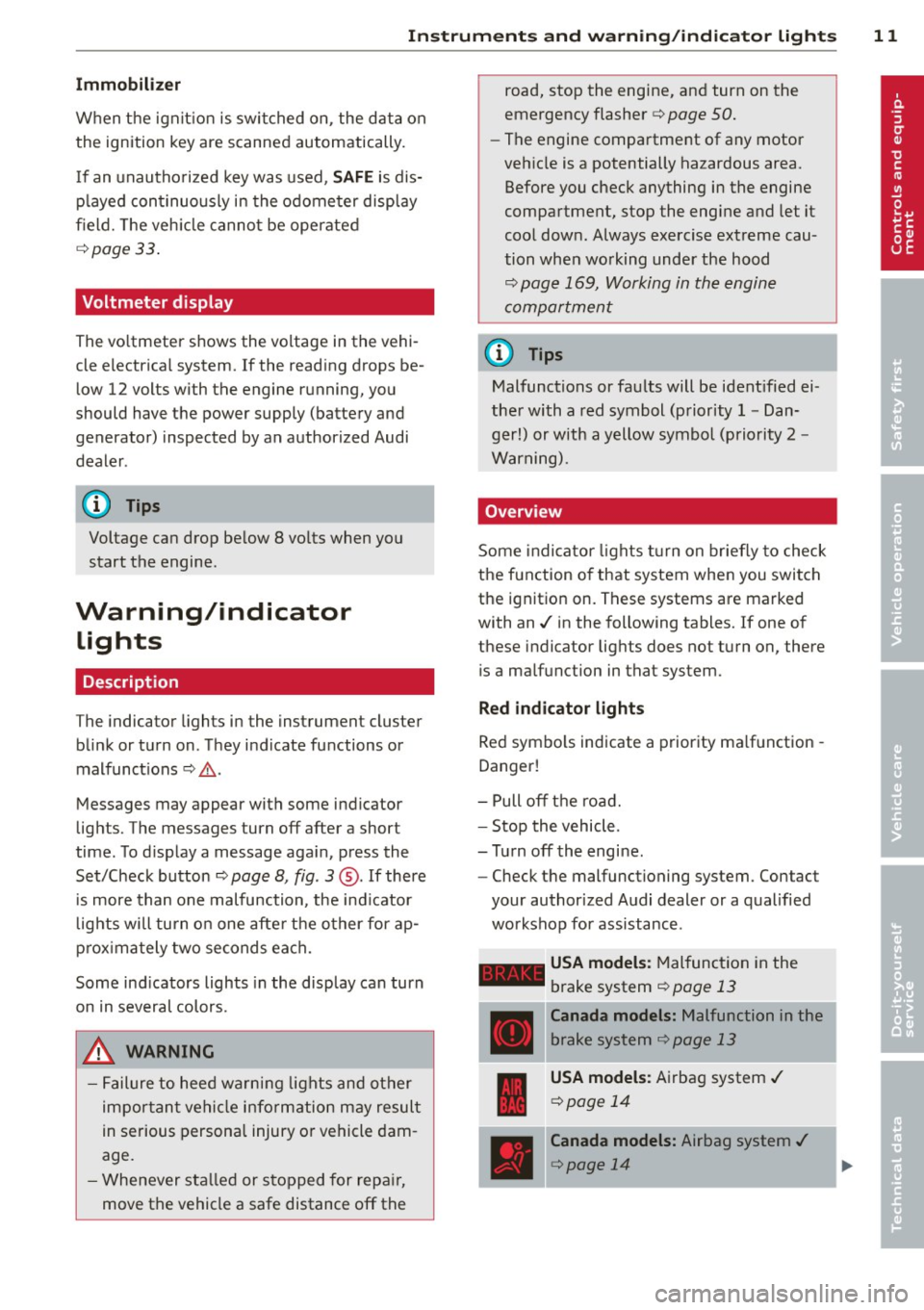
-USA models : Malfunction in the
brake system ¢
page 13
Canada models: Malfunction in the
b rake sys tem
¢ page 13
USA models: A irbag system./
¢ page 14
Canada models: Airbag system ./
¢page 14
Page 21 of 236
Instruments and warning/indicator lights 19
Contact your authorized Audi dealer for assis
tance if necessary.
@ Tips
The brake light switch is only inspected as
pa rt of the functional check after the en
gine is started.
@ Light/rain sensor defective
Applies to vehicles: with automatic headlights
The indicator light indicates a defect in the
automatic headlights/automatic wiper sys
tem.
If the symbol illum inates, the light sensor has
failed. For safety reasons, the low beams are
turned on permanently with the switch in
AU
TO. However, you can continue to turn the
lights on and off using the light switch. In the
case of a defect in the rain sensor, the wind
shield wiper lever functions are still available .
H ave the light/ra in sensor checked as soon as
possible at an author ized Audi dealer.
; Audi magnetic ride
The indicator light monitors vehicle damping.
The indicator light E ill uminates when the ig
nition is switched on as
a function check.
(D Tips
If the ind icator lamp illuminates while you
are driving, there is a malfunct ion in the
veh icle damping. The chass is should be in
spected immediately by an authorized Au
di dealer.
-:;J. Rear spoiler
The warning/indicator light monitors the
electrically retractable rear spoiler .
The warning/indicator light Ii! has the follow
ing functions:
-It comes on for about 3 seconds as a func
t ion check when the ignition is switched on.
- It comes on if there is a ma lfunction in the
electrically retractable rear spoiler . Additional
information about the electr ica lly
retractable rear spoiler
r:;, page 144.
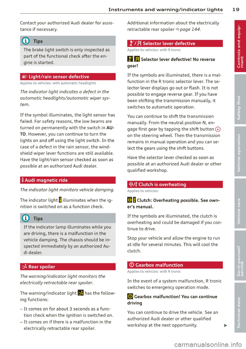
,.YI F{ Selector lever defective
Applies to vehicles : with R tronic
g Ii] Selector lever defective! No reverse
gear!
If the symbols are i lluminated, there is a mal
function in the R tronic selector lever . These
l ector lever d isp lays go out or flash. It is not
poss ible to engage reverse gear. If you have
been shifting the transm iss ion manually, it
switches to automat ic operation.
You can continue to shift the transmission manually. From the neutral position N, en
gage first gear by tapp ing the shift button
0
o n the steering wheel. Then the transmission
remains in manual operat ion and you can se
lect the gears using the s hift buttons.
Have the selector lever checked as soon as
poss ible at an authorized Aud i dealer or other
qualified workshop .
i~Jf Clutch is overheating
Applies to vehicles:
ffl O Clutch: Overheating possible. See own
er's manual.
If the symbols are i llum inated, the clutch is
ove rheating and could be damaged if you con
tinue to drive.
Stop your vehicle and allow the engine to run
at idle for several m inutes . This w ill cool the
clutch.
0 Gearbox malfunction
App lies to vehicles: wit h R tro nic
In the event of a system malfunction, R tronic
switches to emergency ope rat ion mode.
[O) Gearbox malfunction! You can continue
driving
You can continue to drive the vehicle. See an authorized Aud i dealer or other qualified
workshop at the next opportun ity . ..,.
Page 29 of 236

.. If necessary, scroll by se lecting and activat
ing the symbol for "Next page" or "Previous
page".
When you have selected the Computer menu
and activated it by pressing the
I RESET I but
ton, two computer leve ls appear (computer 1
and computer 2). Now you have to select the
level you want using the rocker switch and ac
tivate it w ith the
I RESET I button.
Lap timer
Introduction
The lap timer allows you to record and evalu
ate lap times .
The instrumen t cluster display shows the t ime
in m inutes, seconds and tenths o f a second.
For lap times longer than one hour, the hour
is also shown automatically. The maximum re
cordab le time for a single measurement is 99
h ours , 59 m inutes and 59 and 9/10 seconds.
If t he lap timer reaches th is value, the tim ing
stops on its own or it switches to pause mode
via
c::;, page 28.
A WARNING
Pl ease d evote your fu ll attent ion to driv
ing. As the d river, yo u have comp lete re
sponsibility fo r sa fe ty i n traffic. Only use
t he functions in such a way that you always
ma inta in complete control over your veh i-
de in all traff ic sit uat ions.
(D Tips
All of the trip compu ter functions are
availab le as usua l w hen the lap timer stop
watch is runn ing.
-
Dr iver in formation system 2 7
Selecting the lap timer
---®
Fig. 17 Contro ls
Fi g. 18 D isplay: Lap timer
.. With the ignition on, press the I RESET I b ut
ton @
r=;,fig . 17 unt il the lap timer r=;,fig. 18
appears.
Starting the timer
Fig. 19 D isplay: Lap 1
F ig . 20 D isplay: Lap 1 is saved, lap 2 is started
Page 30 of 236

28 Driver information system
The top row shows the current lap number: e.
g.
LAP 2 ( = second lap).
Starting lap time
.. Press the upper section of the rocker
switch. Row@¢
fig. 19 disp lays the current
lap time.
Saving lap time
.. Press the upper section of the rocker switch
again. This simultaneously starts the meas
urement for the next lap.
After being saved, the first recorded lap time moves from the lowest to the next highest
line in the display@~
fig. 20. The lower line
@ identifies the newly started lap time.
Recording additional lap times
Fig. 21 Display: Lap 2 is saved
After starting the lap timer, a timed lap is
comp leted and stored and t iming beg ins for
the next lap every time the upper section of
the rocker switch is pressed. Continue as de
scr ibed above to measure additional lap
times.
The current lap time is disp layed in the bot
tom line of the display @¢
fig. 21.
After being saved, the last recorded lap time
moves from the lower to the next higher line
on the display @~
fig. 21. The lap time be
fore the last one also
moves up one line @.
The lowest line © identifies the newly started
l ap time.
Displaying split time or inserting a
pause
Split time is indicated by a star.
Fi g. 22 D isplay: Showing a split t ime
It is possible to recall split times for spec ific
stretches. If you wo uld like to insert a pause
during a lap, you can stop the time recording.
Displaying split time or inserting a pause
.. Press on the lower section of the rocker
switch to
display the split time @. While
the split time marked with a star is being
disp layed, the time recording continues to
run in the background .
.. Press the lower section of the rocker switch
again to
insert a pause . Timing is interrupt·
ed, the star in the last row disappears .
Resuming timing
.. Press the upper section of the rocker switch
to resume timing from the split time or pause display.
Switching the display between the lap
timer and trip computer
You can retrieve info rmation from the t rip
computer while the lap timer stopwatch is
runn ing.
Selecting the trip computer
.. Press the I RESET I button briefly to display
the trip computer . You can now operate the
trip computer as usual.
Selecting the lap timer
.. Press the I RESET I button until the lap timer
¢page 27, fig. 18 appears .
Page 74 of 236
7 2 On the road
-The eng ine cann ot be started by pushing
or towing the vehicle.
@ For the sake of the env ironment
To avo id unnecessary engine wea r and to
red uce exhaust emissions, do not let your
vehicle stand and warm up . Be ready to
drive off immediately after starting your
veh icle.
Stopping the engine
On vehicles with R tronic*, the engine can be
turned off in the neutral position N and in
each gear (1 -6 and R).
.,. Turn the ign ition key to position ©
¢ page 70, fig. 82.
A WARNING
-Never turn off the eng ine unti l the vehi
cle has come to a complete stop.
- The brake booster and servotronic on ly
work when the engine is running. With
the ignition turned off, you have to apply
more force when stee ring or braking.
S ince you cannot steer and stop no rma l
ly, this can lead t o acciden ts and ser io us
injuries.
- If the engine has bee n under heavy load
fo r an ext ended period of time, heat
builds up i n the engi ne compa rtme nt af
ter the eng ine is sw itched off -there is a
risk of damaging the engine . Allow the
engine to continue to run at idle for a
sho rt time or drive until it has cooled
down before you turn it off¢
page 151.
- If the engine has been under heavy load
for an extended pe riod of time, it can be
come extreme ly hot. You should not park
your vehicle over easily combustible ob
j ects o r areas (e.g. g rass or leaves). There
i s a r isk of start ing a f ire.
(D Tips
After the engine has been switched off, the
radiator fan can continue to run for up to
10 minutes -even with the ignition switch
ed off. It can also sw itch on again after
some time if the coolant tempe rature rises
as the result of heat b uild up or if the en
g ine compartment is heated by the sun 's
r ays and the eng ine is hot.
Parking brake
Parking brake
When the parking brake is set, it prevents the
vehicle from rolling away unintentionally .
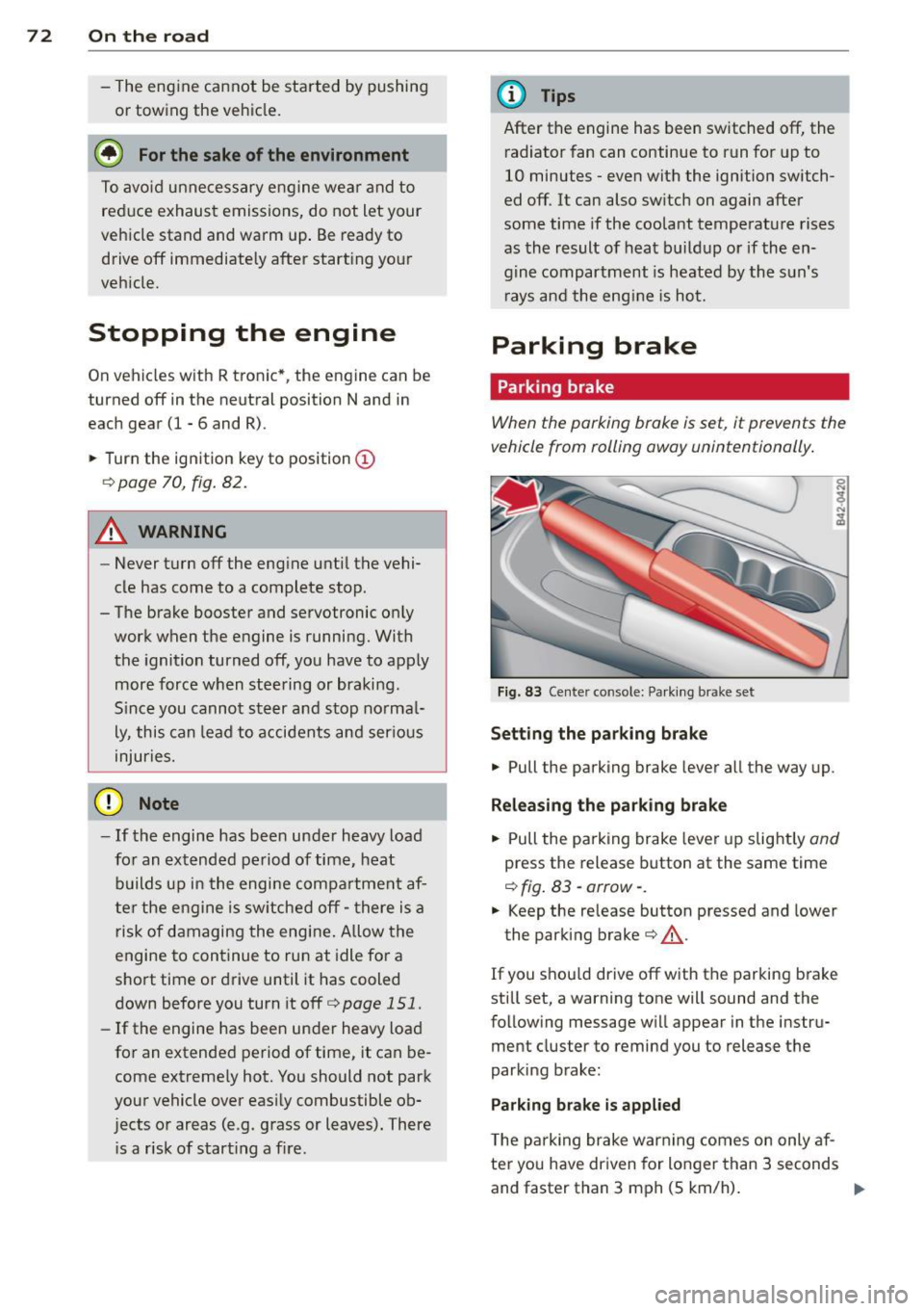
Fig. 83 Center console: Pa rk in g brake set
Setting the parking brake
.,. Pull the parking brake lever a ll the way up.
Releasing the park ing brake
.,. Pull the pa rking brake lever up slight ly and
press the release button at the same time
¢ fig . 83 -arrow- .
.,. Keep the release button pressed and lower
the parking brake¢&_.
If you s hou ld drive off with the parking b rake
st ill set, a warning tone will sound and the
following message wi ll appear in the instru
ment cluster to remind you to release the
parking brake:
Parking brake is applied
T he p arking brake war ning comes on only af
ter yo u have dr iven for longer than 3 seconds
and faster than 3 mph (5 km/h) . .,.
Page 79 of 236
Transmission Manual transmission
Gearshift lever
App lies to vehicles: with manual transmission
The clutch pedal must be depressed all the
way before you can start the engine.
T he manual transmission in your Audi is
equipped with an
interlock-feature.
• Depress the clutch pedal all the way.
• Start the engine with the gearshift lever in
Neutral and the clutch pedal depressed.
(D Note
Always depress the clutch pedal fully when
changing gears . Do not hold the vehicle on
a hill with the clutch pedal partially de
pressed. This may cause premature clutch
wear or damage .
@ Tips
- Resting your hand on the gearshift lever
knob while driving will cause premature
wear in the transmission.
- The back-up lights go on when you sh ift
into Reverse w ith the ignition on.
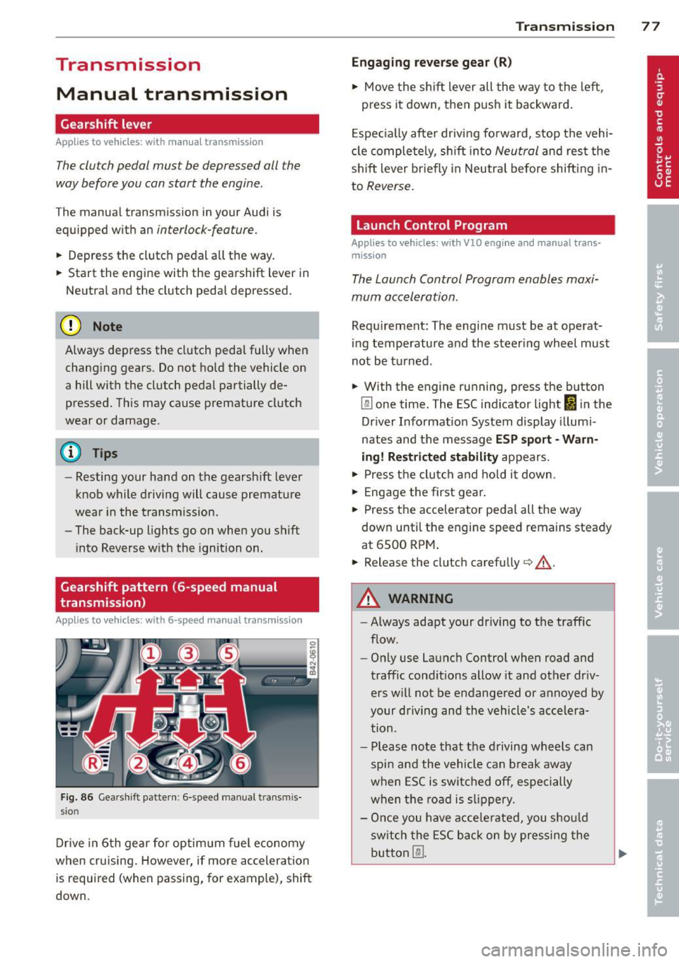
Gearshift pattern (6-speed manual
transmission)
Applies to vehicles: with 6-speed manual transmission
Fig. 86 Gearshift pattern : 6 -speed manual tran smi s
sio n
Drive in 6th gear for optim um fuel economy
when cruising . However, if more acceleration
is required (when passing, for example), shift
down.
Transmission 77
Engaging reverse gear (R)
• Move the shift lever all the way to the left,
press it down, then push it backward.
Especially after driving forward, stop the vehi
cle completely, sh ift into
Neutral and rest the
shift lever br iefly in Neutra l before shift ing in
to
Reverse .
Launch Control Program
Applies to vehicles: with VlO eng ine and manual t ra ns·
miss ion
The Launch Control Program enables maxi
mum acceleration .
Requirement: The engine must be at operat
ing temperature and the steering wheel must
not be turned .
• With the engine running, press the button
Im one time. The ESC indicator light 1B in the
Driver Informat ion System display illumi
nates and the message
ESP sport - Warn
ing! Restricted stability
appears.
• Press the clutch and hold it down.
• Engage the first gear.
• Press the accelerator pedal all the way
down until the engine speed remains steady
at 6500 RPM .
• Release the clutch carefu lly <=> .& ..
A WARNING
- Always adapt your dr iving to the traffic
flow.
- Only use Launch Control when road and
traffic conditions allow it and other dr iv
ers will not be endangered or annoyed by
your driving and the vehicle's accelera
tion.
- Please note that the driving wheels can
spin and the vehicle can break away
when ESC is switched off, especially
when the road is slippery.
- Once you have accelerated, you sho uld
sw itch the ESC back on by pressing the
button
[fil .
Page 82 of 236
80 Transmi ssion
(0 Note
If you must stop on an incline, always hold
the vehicle in place w ith the foot brake to
prevent it from roll ing back. Never hold
the vehicle on an incline w ith a slipping
clutch. The clutch was overloaded if
Clutch
overheat ing! If possib le pl ea se st op ve hi
cle appears in the Driver Information Sys
t em disp lay.
Automatic operation
Ap plies to ve hicles : wit h R tro nic
The forward gears are shifted up or down au
tomatically.
Startin g from a stop
11-Press and ho ld the brake pedal.
11-Tap the se lector lever towards A .
... Re lease the brake pedal and acce lerate
¢ ,& in Manual operation on page 79 .
Under certain circumstances (driving in the
mounta ins for example), it can be beneficia l
to switch tempo rarily to the manual shift pro
g ram ¢
page 79in order to adjust th e gear ra
tios to driv ing cond itions
manually.
Kick-down
A ppl ies to vehicles : wit h R tro nic
When you depress the accelera to r pedal be
yond the resistance po int, R tron ic downsh ifts
into a lower gear, depending on vehicle speed
and engine rpm. The ups hift into the next
h igher gear takes place once the max imum
specified engine speed is reached. Exception:
You have activated the sport funct ion .
A WARNING
Please note that the drive wheels can spin
if kick-down is used on a smooth slippery
road -there is a risk of skidding.
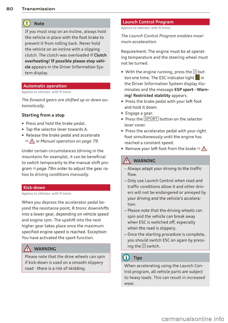
Launch Control Program
App lies to veh icles : w it h R tro nic
The Launch Control Program enables maxi
mum acceleration .
Requirement: The engine must be at operat
ing temperature and the steering wheel must
not be turned .
... With the engine running, press the
I!! but
ton one time. The ESC ind icator light
I in
the Driver Information System d isplay illu
m inates and the message
ESP sport - Warn
ing! R estr icted stability
appears .
... Press the b rake pedal w it h your l eft foot
and hold i t down.
11-Eng age a gear.
11-Press the I SPORT I button on the selector
lever cover .
... Press the accelerator peda l wit h your right
foot sim ultaneously until the engine has
reached a constant speed .
... Remove your left foot from the brake¢,& .
A WARNING ,-
-Always adapt your dr iving to the traffic
f low.
- Onl y use Launch Control when road and
traffic cond itions allow it and ot her dr iv
ers will not be endange red o r annoyed by
your driving and the vehicle's ac celera
t ion .
- Please note that t he d riving wheels ca n
sp in and the vehicle can br eak away
when ESC is swi tched off, especially
when the roa d is s lippery.
- Once the s tarting procedure is comple te,
you sho uld sw itch ESC on again by press
i n g the
I!] switch.
(D Tips
When a ccele rat ing using the Lau nch Con
t rol program, all vehicle parts are s ubje ct
to heavy loads . This can result in increase d
wear .
-
Page 88 of 236
86 Parking system
The following steps app ly only when there is
no obstacle such as a wall near the parking
spot. Otherwise, please read the informat ion
prov ided in the "Parking Next to Obstacles"
section.
.. Activate the turn signal.
.. Position your vehicle parallel to the edge of
the street, approximately 3 ft. (1 m) from a parked vehicle .
.. Switch the navigation system and the nav i
gat ion system d isplay on.
.. Se lect rev erse gear . T he parking aid turns
on and pa rking mode 1 appea rs on the dis
play.
.. Press the cont ro l button 1 on the nav iga
tion system ¢
fig. 98. Parking mode 2 ap
pears .
.. Back up and align your vehicle so the b lue
area @ borders on the rear end of the vehi
cle or on the parking spot line. The blue area
represents an extension of the ve hicle's out
line by approximately 16 ft (5 meters) to the
r ear. The long side of the blue area shou ld
be o n the curb. The entire blue area must fit
i n to the par king spot .
.. Wi th the veh icle stopped, turn the steer ing
wheel to the right as far as it wi ll go .
.. Back into the parking spot unti l the blue
curve to uches the curb¢
fig. 99. Stop the
vehicle .
.. With the veh icle stopped, turn the steer ing
whee l to the left as fa r as it wi ll go .
.. Co nti nu e to back into the pa rk ing spot until
the vehicle is par ked para llel to the curb. @
ma rks the rear bumper. Stop the vehicle
when the red orientation line@ borders an
obje ct ¢ .&,. . Keep an eye on the fron t of
yo ur vehicle while doing this
c> (D.
Parking next to obstacles
When the re is an obsta cle (suc h as a wall)
next to the pa rking spot, choose a spot w ith
mo re space on the sides. Pos ition the long
side of the blue area so t hat there is sufficient
space from the c urb. The area must not be on
the c urb. Yo u wi ll also need to start turning
the steering wheel much ear lier. There should
be a suffic ient amount of space between the c
ur b and the blue curve, and the b lue curve
c> fig. 99 must not touch the curb.
A WARNING
--The rearview came ra does not show the
entire area behind the vehicle¢
page 82,
fig. 93. Watch out especially for small
children and anima ls . The rear view cam
era can not always detect them, posing
ris k of an accident!
- Please note that objects not touching the ground can appear to be farther away
than they really a re (fo r example, the
bumper of a vehicle or the rear of a
t ruck). In th is case, you should not use
the orientation lines to help wi th par k
ing, which poses dan ger of an accident!
(D Note
In the navigation system disp lay, the direc
tion o f tra ve l o f th e veh icle re ar is rep re
sented depend ing on the steering wheel
angle. The vehicle front swings out mo re
than the vehicle rear . Ma inta in p lenty of
distance so that your o utside mirror or a
corner of you r vehicle does not coll ide with
any obstacles . This can damage to your ve
hicle .
@ Tips
The left o r right orientation lines and su r
faces will be disp layed, depending on t he
turn s ignal being used .
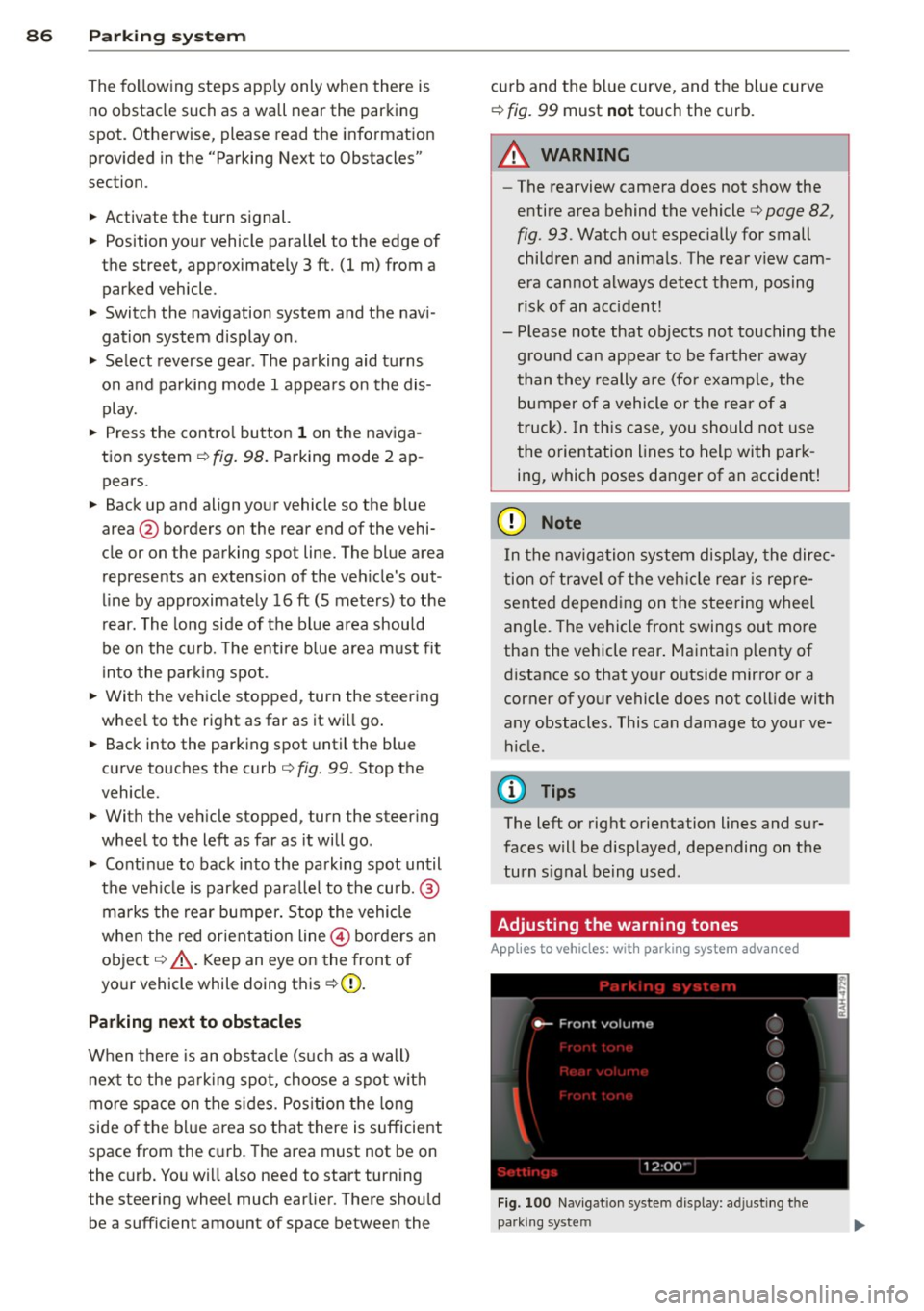
Adjusting the warning tones
Applies to vehicles: with parking system advanced
Fi g. 100 N av igation syste m dis pl ay: a djustin g t he
park ing syst em
Page 90 of 236
88 Homelin k®
Homelink ®
Universal remote
control
General information
The Homelink universal remote control can
be programmed with hand-held transmitters
from existing equipment.
You must first program the Homelink ® trans
mitter before you can use the system
~ page 88, Programming the Homelink ®
transmitter.
In order to program the Homelink® transmit
ter for devices utilizing rolling code, a second person on a ladder who can safely reach the
garage door opener motor is recommended.
It is also necessary to locate the "learn" but
ton on your garage door opener motor . Refer
to the operating instructions for the opener,
as the location and color of this button may
vary by manufacturer .
You can still use the original remote control
for the device at any time.
A WARNING
-
- Never use the Homelink® transmitter
with any garage door opener that does
have not the safety stop and reverse fea
ture as required by federal safety stand
ards. This includes any garage door open
er model manufactured before April 1,
1982.
- A garage door opener which cannot de
tect an object, signaling the door to stop
and reverse does not meet current feder
al safety standards. Using a garage door
opener without these features increases
risk of serious injury or death.
- For safety reasons never release the
parking brake or start the engine while
anyone is standing in front of the vehicle.
- A garage door or an estate gate may
sometimes be set in motion when the
Homelink ® remote control is being pro
grammed. If the device is repeatedly ac- tivated, this can overstrain motor and
damage its electrical components
-an
overheated motor is a fire hazard!
- To avoid possible injuries or property
damage, please always make absolutely
certain that no persons or objects are lo
cated in the range of motion of any
equipment being operated.
{!) Tips
- If you would like more information on
Homelink ®, where to purchase the
Homelink ® compatible products, or
would like to purchase the Homelink®
Home Lighting Package, please call toll
free: 1-800-355-3515.
- For Declaration of Compliance to United
States FCC and Industry Canada regula
tions ~
page 222.
Programming the Homelink ®
transmitter
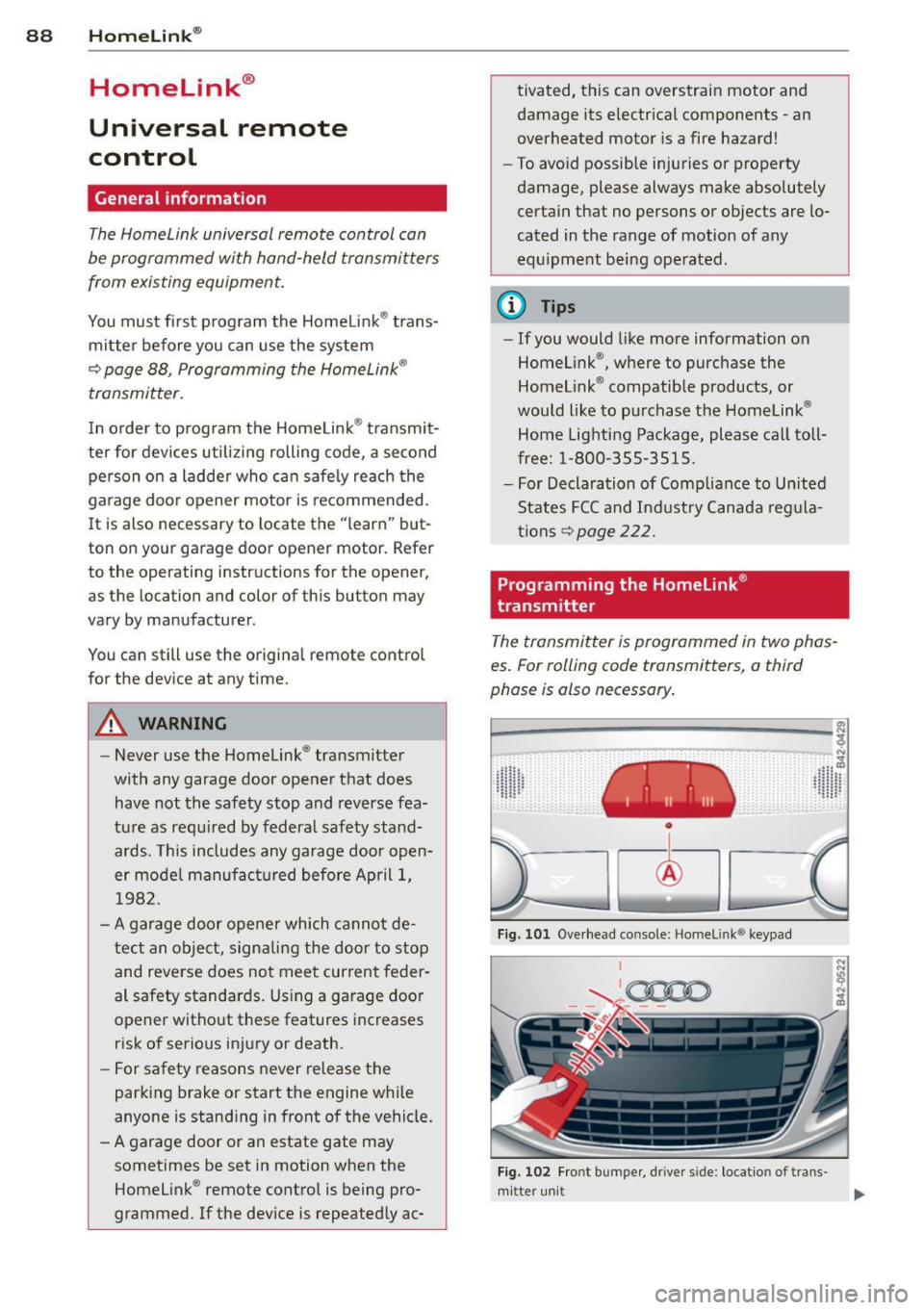
The transmitter is programmed in two phas
es. For rolling code transmitters, a third
phase is also necessary.
~----------------- ~ ,:.
~
Fig. 101 Overhead console: Homeli nk® keypad
I
'-..~0000 - - ,r.;-_ - -
Fig. 102 Fro nt bumper , driver side : loc ation of trans -
mi tter unit ..,_
Page 91 of 236
Phase 1:
p rogramming th e overh ead k eypad
1. Make sure your vehicle is wit hin operating
range of the remote controlled garage
door opener.
2. Set the parking brake
q A in General in
formation on page 88.
3 . Turn the ignition on . Do not start the en
g ine!
4. P ress and hold the two outs ide Home
Link ® buttons
(D and @for approxi
mately 20 seconds until indicator light @
¢fig. 101 begins to flash . Then release
both buttons. Do not ho ld the buttons for
longer than 30 seconds.
.,. This procedure only needs to be performed
once . It erases the factory-set default codes
and does not have to be repeated to pro
gram add it ional remote controls.
S. P ress and hold the Home Link ® button
(D ,
® or @ until the indicato r ligh t@
starts flashing
slowly. Re lease the bu tton.
.,. The system will remain in programming
mode for 5 minutes . Co to the front of the
vehicle and proceed with phase 2 .
Phase 2:
programmin g th e bumper mounted tran s
m itter
6. Hold the original remote control at a dis
tance between 0 -6 in. (0 -15 cm) from the
bumper below the appropriate headlight
for your vehicle
c:!;> fig. 102 (use the short
est distance possib le).
7 . A im the remote con trol just be low the
driver sid e head light.
8. P ress and hold the activation button on
the remote contro l.
.,. May be different in Canada.
If so, press and
re-press (cycle) the act ivation button on your
remote control every two seconds.
9. The emergency flashers will flash
three
time s
(after about 15-60 seconds) when
the programm ing is successful. Release
the butto n on the remote control.
.,. To program more devices, repeat steps 4 to
9.
Homelink ® 89
10. Press and hold the tra ined Homelink ®
button and observe the indicator light @
qfig. 101 .
.,. If the indicator light is solid/contin uous,
programm ing is complete and your device
should activate when you press and release
the t ra ined Homel ink® button .
.,. If the ind icator light blinks rapidly fo r 2 sec
onds and is the n a solid/continuous light,
p roceed w ith phase 3 to program a roll ing
code device.
Phase 3: rolling code programming
.,. A second pe rson on a ladder who can safely
reach the garage door opene r motor is rec
ommended .
11. Lo ca te the "learn" button on the ga rage
doo r opener motor ( re fer to the operating
instructions for the opener, as t he loca
tion of t his button may vary by man ufac
turer).
12. Press and re lease the learn button on the
garage door opener motor .
.,. Not e: once the button is pressed, there are
30 s econds in wh ich to in it iate the next
step.
13. On t he Homelink ® keypad inside the vehi
cl e, firmly press and ho ld the Homel in k®
bu tton prev iously programmed in phases
1 and 2 for two seconds and release. Re
peat this sequence
twice.
.,. Some vehicles may require the press/hold/
release sequence up to three times to com
plete t he trai ning process .
.,. Homelink ® should now activate your rolling
code equipped device.
If the S m inute time limit is exceeded, the
emergency flash ers will flash one time to in
dicate that the p rocess has been te rm inated.
In this case, repeat steps 4 t hrough 9.
If the emergency flashers do not flash
three
times (after about lS-60 seconds), program ming was not successful. In this case, repeat
steps 4 through 9 .
Remote contro l units for garage door openers
in Canada are set to stop transmitting radio
frequency sig nals afte r two seconds. This t ime
Ill-