mirror AUDI R8 SPYDER 2015 Owners Manual
[x] Cancel search | Manufacturer: AUDI, Model Year: 2015, Model line: R8 SPYDER, Model: AUDI R8 SPYDER 2015Pages: 232, PDF Size: 58.36 MB
Page 9 of 232
..... N
r-N "': ..... \!) Ll'I
N Ll'I .....
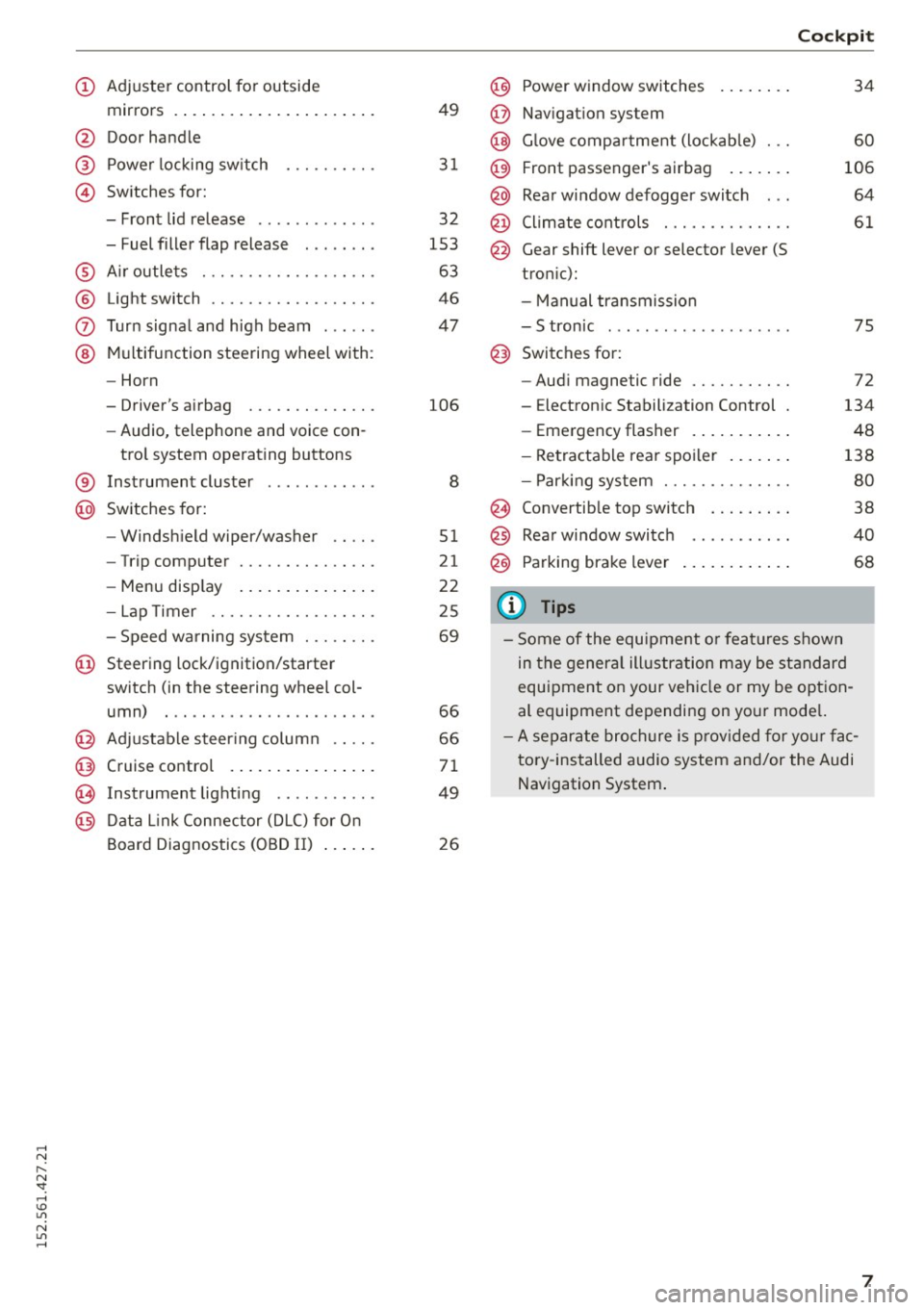
(!) Adjuster control for outside mirrors .. .. .............. ... .
@ Door handle
@ Power locking switch
© Switches for:
- Front lid release ........... . .
- Fuel filler flap release ... .. .. .
® A ir outlets ............ .... .. .
® Light switch ........... .... .. .
(J) Turn signal and high beam . .. . . .
@ Multifunction steering wheel with :
- Horn
- Driver's airbag ....... .. .. .. .
- Audio, telephone and voice con-
trol system operating buttons
® Instrument cluster
@ Switches for:
- Windshield wiper/washer
- Trip computer ........ .. .. .. .
- Menu display .............. .
- Lap Timer ........... .. .. .. .
- Speed warning system ... .. .. .
@ Steering lock/ignition/starter
switch (in the steering wheel col- umn) .. . .... ............. .. .
@ Adjustable steer ing column .. .. .
@ Cruise control ............... .
(§ Instrument lighting .... .. .. .. .
@ Data Link Connector (DLC) for On
Board Diagnostics (OBD II) ... .. .
49
31
32
153
63
46
47
106
8
51
21
22
25
69
66
66
71
49
26
@ Power window switches
@
@
@
@
@
@ Navigation system
Glove compartment (lockable)
Front passenger's airbag ...... .
Rear window defogger switch ...
Climate controls .. .......... . .
Gear shift lever or selector lever (S
tronic):
- Manual transmission
- S tronic ..... .............. .
@) Switches for:
- Audi magnetic ride
- E lectronic Stabilization Control
- Emergency flasher .......... .
- Retractable rear spoiler ...... .
- Parking system ............ . .
@ Convertible top switch ........ .
@
@ Rear window switch
Parking brake lever
(D Tips
Cockpit
34
60
106
64
61
75
72
134 48
138
80
38
40
68
- Some of the equipment or features shown
in the general illustration may be standard
equipment on your vehicle or my be option
al equipment depending on your mode l.
- A separate brochure is p rovided for your fac
tory-installed audio system and/or the Audi
Navigation System.
7
Page 48 of 232

Clear vision
Clear vision Lights
Switching the headlights on/off
F ig. 55 Inst rument pane l: ligh t switch (automatic head
and taill ig ht control)
Switching on the side marker lights
"'T urn the light switch to :oo:.
Switching on the headlights and high beam
"'Turn the light switch to io.
"'Push the high beam lever forward towards the
instrument panel~
page 47.
Switching off the lights
"'Turn the light switch to 0.
Switching on automatic head- and taillight
control
"'Turn the light switch to AUTO ~ fig. 55.
The headlights and taillights will come on auto
matica lly when the ignition is switched on and
the light switch is in the position AUTO (on ly in
nighttime conditions). When switching
off the ig
nition, the headlights will go
off and only the
side marker lights will remain lit.
Daytime running lights
USA models: The daytime running lights will
come on automatica lly when the ign ition is
sw itched on and the light switch is in the position
AUTO (only in daylight conditions).
Canada models: The daytime running lights will
come on automatica lly when the ign ition is
sw itched on and the light switch is in the position
0, AUTO (only in daylight condit ions) or :oo;.
46
Automatic head- and taillight control
In the switch position AUTO the automatic head
and taillight contro l is activated . Light sensors
are located in the ins ide mirror housing and con
stantly check the light conditions surrounding
the vehicle. If ambient brightness falls below a
factory set value (e.g. when driving into a tun
nel), the head- and taill ights including the li
cense plate illumination are automatically turned
on . When ambient brightness increases again,
the externa l lights are turned
off again~,& . In
the switch position
AUTO , the low beams are
turned
off when the ignition is switched off. The
remaining lights are turned
off when the key is
taken o ut of the ignition lock .
With automatic head-and taillight control, the
high-beam function is also available, but with
one restriction: If you have not switched the high
beams back to low beams during automatic
headlight operation (for example, after driving
through a tunne l), only the low beams come on
the next time automatic headlights are switched
on . To use the high beams, you first have to pull
the h igh beam lever back and then push the lever
forward again.
The side marker lights and headlights can be
switched on manually by turn ing the light sw itch
to the des ired pos it ion .
Light sensor malfunction
If there is a light sensor ma lfunction, the symbol
El comes on in the display. For safety reasons,
the low beams are turned on permanently with
the sw itch in
AUTO. H owever, you can continue to
turn the lights on and
off using the light sw itch.
Have the light sensor checked as soon as possible
at an authorized Audi dealer .
Coming home/leaving home function
The function is sw itched on when the sw itch is in
the
AUTO pos ition and the function is shown as
active in the driver information system.
The
coming home function illuminates the area
around t he vehicle when the igni tion is switched
off and the driver's door is opened. The length of
time the lights rema in on can be set in the menu
display
( Lights > Exterior lights > coming home ). IJJ,,
Page 49 of 232
.... N
l'
N "1: .... I.O
"' N
"' ....
The leavin g home function i lluminates the area
around the vehicle when un locking it .
A WARNING
-Never use daytime running lights to see
where you are going. They are not bright enough and w ill not let you see far enough
ahead for safety, especially at dusk or when it is dark . Be aware of changes in outside
light cond itions when you are dr iv ing and re·
spond by switching on your low beams.
- Automatic head· and taillight control is only
intended to assist the d river. This feature
does not relieve the driver of his responsibi l
ity to check t he headlights a nd to turn t hem
on manually according to the cur rent lig ht
and visibility conditions. For example, fog
and rain cannot be detected by the light
sensors. Consequent ly, always switch the
headlights on under these weather cond i·
tions and when dr iv ing in the da rk.
- Crashes can happen when yo u cannot see
the road ahead and when you cannot be
seen by other motorists.
- Always turn on the headlights so that you
can see ahead and so that others can see
your car from the back.
- Please observe lega l regulations when using
the light ing systems described .
@ Tips
-Always observe the specific local regulations
for your area when to use your lights.
- Turn on low beams as evening app roaches
or in conditions of poor visib ility.
- Do not attach stickers to the windshie ld in
front of the sensors as this can disab le the
automat ic head- and taill ight control and
the automatic glare-dimming of the rear·
v iew mirror(s) *.
- If you remove the ignit ion from the ign it ion
lock while the headlights are still on, a buz
zer w ill sound as long as the dr iver's door is
open to remind you to t urn off the lights .
- In the AUTO mode, the low beams are
turned off when the ignition is t urned off.
The remaining lights ar e turned off when
t h e key is taken ou t of the ignition.
Cle ar vi sion
-In cool or damp weather conditions the
head lights may fog
over temporarily on the
inside .
- The c ritical factor is the temperature dif
ference between the inter io r and the exte·
rior of the hea dlight lens .
- W ith the mai n beams switched on, the
lig ht-em itting area w ill be free of conden
sation after a short time, however the
e d ges of the glass may still be fogged.
- This physical phenomeno n has no effect
on the life of your veh icle's lighti ng sys
tem .
Turn signals and high beam lever
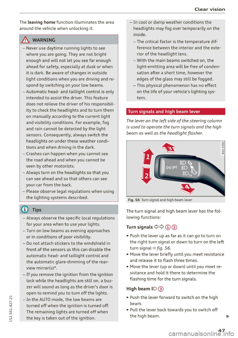
The lever on the left side of the steering column
is used to operate the turn signals and the high
beam as well as the headlight flasher.
t
t
Fig . 56 Turn signal and high bea m leve r
The turn signa l and high beam lever has the fo l
lowing functions :
Turn signal s¢¢ ©@
.,. Push the lever up as far as it can go to t urn on
the right turn signa l or down to turn on the left
turn signal
q fig. 56.
.,. Move the lever br iefly u ntil you meet res istance
and re lease it to flash three times.
.,. Move the lever (up or down) until you meet re
sistance and hold it there to determine the
flash ing time fo r the turn signa ls .
High beam ~D @
.,. Push the lever forward to sw itch on the h igh
beam.
.,. Pull the lever back towards yo u to switch off
the high beam.
47
Page 51 of 232
.... N
l'
N "1: .... I.O
"' N
"' ....
With the door contact circuit, the interior lights
turn on as soon as you unlock the veh icl e or open
the doors . The interior lights are also turned on
when the ignition key is removed . The lights turn
off about 30 seconds afte r the doors are closed .
When the veh icle is locked or when the ignition is
turned o n, the inter ior lights are turned off .
When a door is open , the interior lights are
turned off after about 10 m inutes to preven t bat
tery draining .
T he brightness of the lights is controlled a uto
mat ica lly by a d immer when they a re sw itched
on/off.
Instrument panel illumination
T he illumination of the instruments, displays
and the center console can be adjusted .
Fig . 59 In strument pa nel ill uminatio n
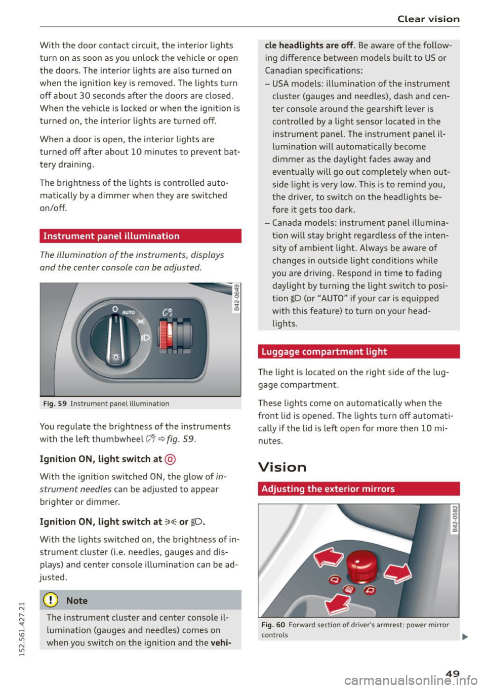
You regulate the brightnes s of the ins truments
with the left th umbwhee l
C:1 i::;,fig. 59.
Ign ition ON , light switch at @
With the ignition switched ON, the glow of in
strument needles
can be adjusted to appear
brighter or d immer .
Ignition ON , light switch at :oo~ or tD .
With the lights sw itched on, the brightness of in
strument cluster (i.e. needles, gauges and dis
plays) a nd center console il lum ination ca n be ad
justed .
(D Note
The instrument cluster and center console il
lum inat io n (gauges and needles) comes on
when you sw itch on the ig nitio n and the
ve hi-
Cle ar vi sion
cle headlight s are off . Be aware of the fo llow
ing difference between models b uilt to US or
Canadian specif ications:
- USA models: ill umination of the i nstr ument
cl uster (gauges and need les) , dash and cen
ter console around the gearsh ift lever is
controlled by a light sensor located in the
instrument panel. The instrume nt pane l il
lum ination w ill automatically become
dimme r as the daylight fades away and
eventua lly will go out comp letely when out
side light is very low . Thi s is to rem ind you,
t he driver, to switch on t he headlights be
fore it gets too dark .
- Cana da model s: instrument panel illumina
t ion will s tay bright regar dless o f the inten
si ty of ambien t light . Always be aware o f
changes in outside lig ht conditions while
you are driving. Respond in t ime to fading
daylight by turning the light sw itch to posi
tion ~D (or "AUTO" if your car is equipped
w ith this feat ure) to turn on your head
lights .
Luggage compartment light
The light is located on the right side of the lug
gage compa rtment .
These lights come on automatically when the
front lid is opened . The lights turn off automati
c a lly if the lid is left o pen fo r more then 10 mi
nutes .
Vision
Adjusting the exterior mirrors
Fig. 60 Forward sect io n of driver 's armrest: pow er mirr or
con trol s ...
49
Page 52 of 232
Clear vision
Turn the knob to the desired position :
Q/P -In this position, you can adjust the driv
er's and front passenger 's exterior mirrors by
turning the knob in the desired direction .
(@ -The mirrors are heated depending on the
outside temperature.
8 - The exterior mirrors fold in*
You are well-advised to fold the exterior mirrors in when maneuvering in tight spaces or when
leaving the car parked close to other vehicles.
A WARNING
-
- Curved (i .e. convex) mirror surfaces in
crease your field of view . Remember that
vehicles or other objects will appear smaller
and farther away than when seen in a flat
mirror. If you use this mirror to est ima te
distances of following vehicles when chang
ing lanes, you could estimate incorrectly
and cause an accident.
- If th e mirror housing is moved unintent ion
a lly (for example, wh ile parking your vehi
cle), then you must first fold the mirror
electrically. Do not readjust the mirror hous
ing manually. You could damage the motor
which controls the mirror.
- If you wash the vehicle in an automatic car
wash, you must fold the exterior mirrors in
to reduce the risk of damage to the mirrors.
Never fold power folding exterior mirrors*
by hand . Only fold them in and out using
the power controls.
(D Tips
If there should be a malfunction in the elec
trical system, you can still adjust the exter ior
m irrors by pressing the edge of the mirror .
50
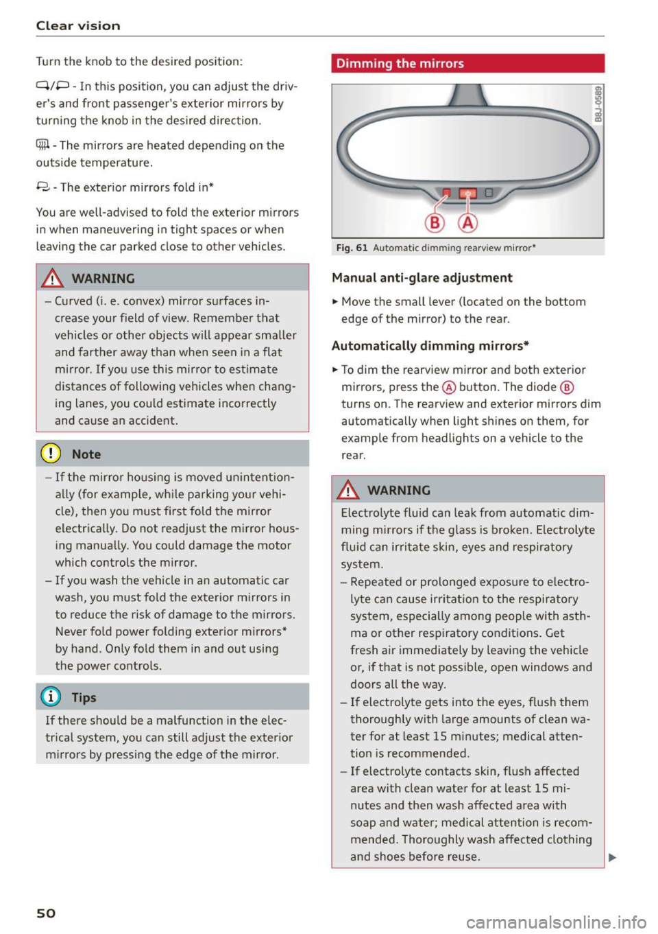
Dimming the mirrors
Fig. 61 Auto matic d immin g rearv iew mirror*
Manual anti-glare adjustment
.. Move the small lever (located on the bottom
edge of the mirror) to the rear .
Automatically dimming mirrors*
.. To dim the rearview m irror and both exterior
mirrors, press the@ button. The diode @
turns on . The rearview and exterior mirrors dim
automatically when light shines on them, for
example from headlights on a vehicle to the
rear.
A WARNING
Electrolyte fluid can leak from automatic dim
ming mirrors if the glass is broken. Electrolyte
fluid can irritate skin, eyes and respiratory
system.
- Repeated or prolonged exposure to electro
lyte can cause irritat ion to the respiratory
system, especially among people with asth
ma or other respiratory conditions. Get
fresh air immediately by leaving the vehicle
or, if that is not possible, open windows and
doors all the way.
- If electrolyte gets into the eyes, flush them
thoroughly with large amounts of clean wa
ter for at least 15 minutes; medical atten
tion is recommended .
- If electrolyte contacts skin, flush affected
area with clean water for at least 15 mi
nutes and then wash affected area with
soap and water; medical attention is recom
mended. Thoroughly wash affected clothing
and shoes before reuse.
Page 53 of 232
.... N
l'
N "1: .... I.O
"' N
"' ....
-If swallowed and person is conscious, rinse
mouth with water for at least 15 m inutes.
Do not induce vomit ing unless instructed to
do so by medical professional. Get medical
attent ion immed iate ly .
(D Note
Liquid electro lyte leaking from broken mirror
glass will damage any plastic surfaces it
comes in contact with. C lean up spilled elec
trolyte immed iately w ith clean water and a
sponge.
@ Tips
- Switch ing off the dimming function of the
i nside rear view mir ror also deactivates the
a utomat ic dimming f unction of the exte rior
mir ro rs .
- The au tomatic d imm ing mir ro rs do not d im
when the interior lig hting is turned on or
t h e reverse gear is selecte d.
- Automat ic dimming for the m irror only op
e rates p rope rly if t he lig ht st riking the in
s id e mir ro r i s no t hindere d in any way.
Sun visors
A_.... ,_""''""' 1-----
"~ I~If:._-:::~ ...._ __ ...,....;;;;:;;..,..........., -
~~==.i.=J:Z=t ----------·---
___ , ...... __ ....,.....,_ii,iiiiiiiiioioii=------------i
Fi g. 62 Su n viso r
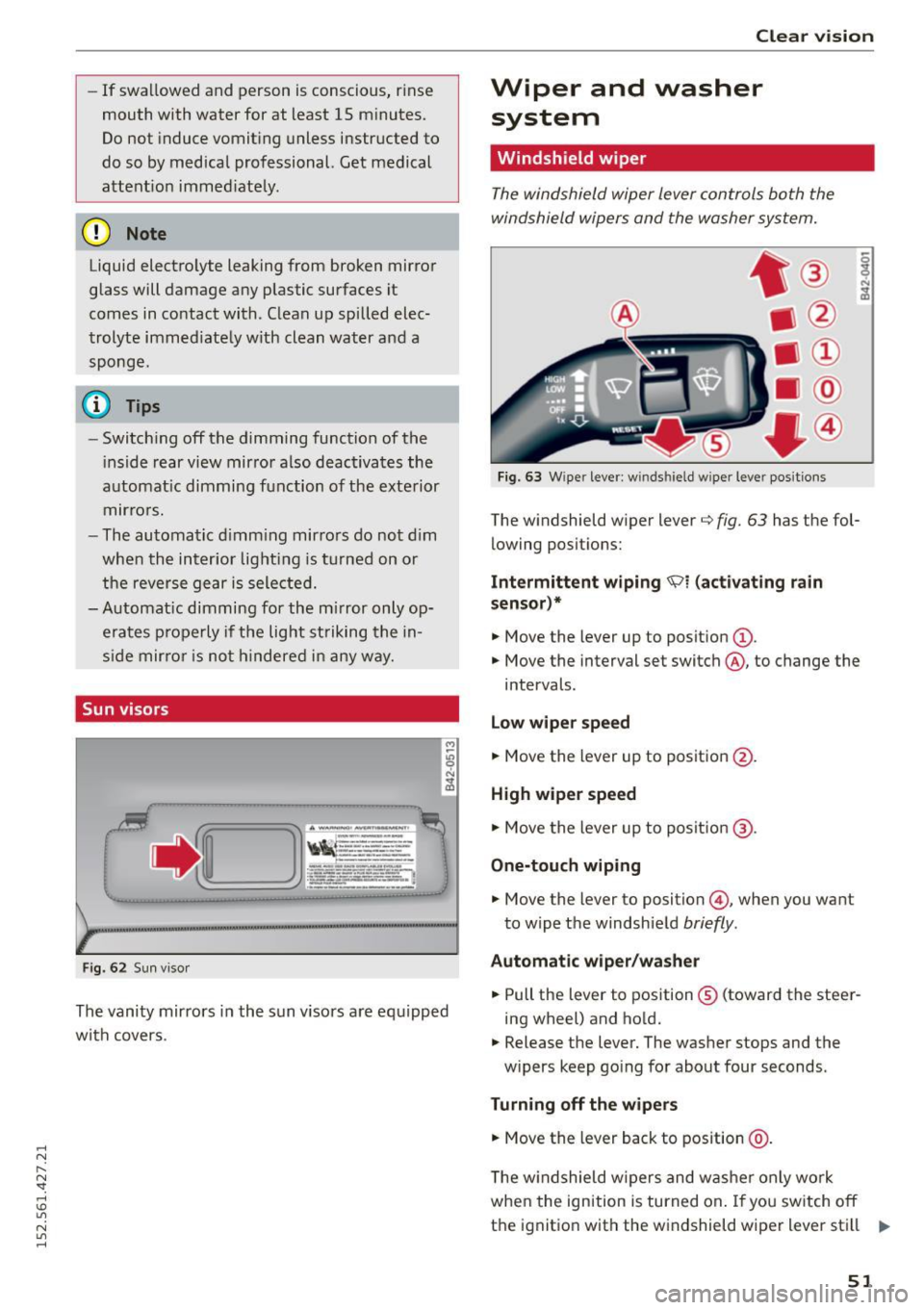
The vanity mir rors in the sun visors a re eq uipped
with covers .
Clear vi sion
Wiper and washer
system
Windshield wiper
The windshield wiper lever controls bo th the
windshield wipers and the washer system.
Fi g. 63 W iper lever: w indshield w iper leve r posit ions
The w indshield wiper lever q fig . 63 has the fol
lowing posit ions:
Intermittent wiping ~1 {act ivating rain
sensor)*
• Move the lever up to posit ion (D .
.,. Move the interval set switch@, to change the
intervals.
Low wipe r speed
.,. Move the lever up to posit ion @.
High wiper speed
.,. Move the lever up to posit ion @.
One-touch wiping
.,. Move the lever to position @, when you want
to w ipe the windshie ld
briefly .
Automatic wiper /washer
.,. Pull the lever to position ® (toward the steer
ing wheel) and hold.
.. Release the lever. The washer stops and the
w ipers keep go ing fo r about four seconds.
Turning off the w iper s
.,. Move the lever back to position @ .
The w indshield w ipers and w ashe r only work
whe n the ign ition is turned on . If you sw itch off
t h e ignit ion with the windshield wiper lever sti ll .,..
51
Page 56 of 232
Clear vision
... Rotate the w iper blade in the direction of the
arrow @c:>
fig. 65 away from the wiper arm.
... Lift the wiper blade
off in the direction of the
arrow @.
Install ing the wiper blade
" Place the rounded end of the wiper onto the
end of the wiper arm in the
oppo site direction
to the arrow @c:>
fig. 65.
"Squee ze the corrugation on the wiper until you
hear it click in the wiper arm .
" Fo ld the w iper arm back onto the windshield .
... Switc h the ignition on and move the wiper lever
down br iefly
c:> page 51, fig. 63 . The wiper w ill
move back to the park position .
_& WARNING
For your safety, you should replace the wiper
blades once or tw ice a year . See your a utho r
ized Audi dea le r f or replacement b lades.
(D Note
- The wipe r blades may only be changed
c:> page 53 in the serv ice position! O ther
wise, you r is k damaging the paint on the
front lid or t he windshie ld wiper motor.
- To he lp preven t damage to the wipe r sys
tem, a lways loosen blades which are frozen
to the windshie ld before ope rating wipers .
- To he lp prevent d amage to w iper blades, do
not use gaso line, kerosene, paint th inner, or
other solvents o n or near the wiper b lades.
- To he lp prevent damage to the wipe r arms
or other components, do not attempt to move the wipers by hand .
- Commerc ial hot waxes applie d by au tom atic
ca r washes affect the cleanability of the
glass surface .
- T he front wipe r blades a re d ifferent le ng ths;
the blade on the driver 's side is longer .
54
Digital compass
Activating or deactivating the compass
Applies to ve hicles: w ith d igital compass
Fig. 66 Insi de rea rv iew m irror: d ig ital co mpass activated
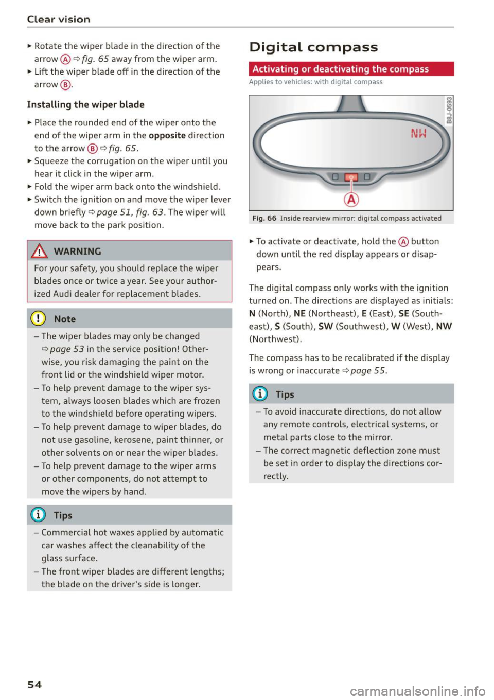
... To activate or deactivate, hold the @button
down until the red display appears o r disap
pears .
The dig ital compass only works with the ignition
turned on . T he d irect ions are displayed as init ials:
N (North), NE (Northeast), E (East), SE (South
east),
S (South), SW (Southwest), W (West), NW
(Northwest).
The compass has to be recalibrated if the d isplay
i s wrong or inaccurate c:>
page 55.
@ Tips
-To avoid inaccurate directions, do not allow
any remote co ntro ls, electrical systems , or
meta l parts close to the mirror .
- Th e correct magnet ic deflection zone must
be set in order to display the directi ons cor
rectly.
Page 57 of 232
.... N
l'
N "1: .... I.O
"' N
"' ....
Setting the magnetic deflection zone
Applies to vehicles: with dig ital compass
®
F ig. 67 Magnetic deflect io n zon e bou ndaries
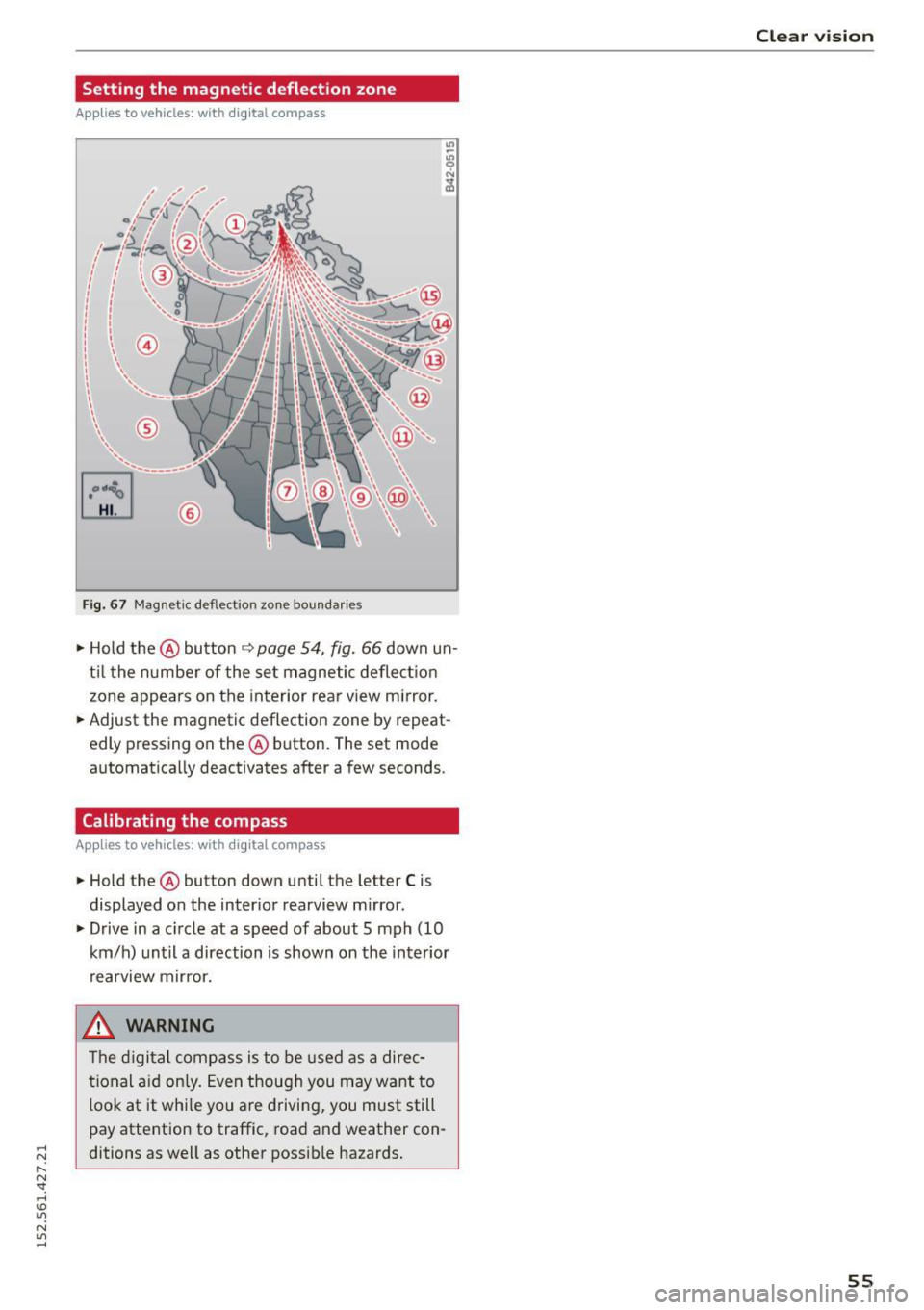
• Hold the@ button ~ page 54, fig. 66 down un
til the number of the set magnetic deflection
zone appears on the interior rear view mirror .
• Adjust the magnetic deflection zone by repeat
edly pressing on the @ button . The set mode
automatically deactivates after a few seconds .
Calibrating the compass
Applies to vehicles: with dig ital compass
• Hold the@ button down until the letter C is
displayed on the interior rearview mirror.
• Drive in a c ircle at a speed of about 5 mph
(10
km/h) until a direction is shown on the interior
. . rearv1ew mirror.
_& WARNING
-
The digital compass is to be used as a direc
tional aid only. Even though you may want to
loo k at it while you are driving, you must still
pay atte ntion to traffic, road and weather con
ditions as well as other possible hazards.
Clear vision
55
Page 83 of 232
..... N
r-N "': ..... \!) 1.1'1
N 1.1'1 .....
area roughly corresponds to the area in¢ fig. 91
and (D ~ fig . 92. Orientation lines and colored
surfaces are projected in the area shown, which
can help you with parking and maneuvering. Ob
jec ts that are located in an area that is not cap
tured by the camera@¢
fig. 92 and that are
closer to the bumper will not appea r on the navi
gation system display .
We recommend that you practice park ing with
the rearview camera in a traffic -free location o r
parking lot to become familiar w ith the system,
the orientation lines, a nd their funct ion . There
should be suff icient light and good weather con
d itions w hen do ing so.
In the nav igat io n system display, objects or
vehicles appear closer or fu rther away if:
Objects or vehicles appear closer or farther away in the navigation system if :
- you are driving in reverse gear from a level sur
face onto an incl ine, or a downward slope,
- you are driving in reverse gear toward protrud-
ing objects .
The accuracy o f the orientation lines and blue
surfaces diminishes if:
- the rearv iew came ra does not p rovide a reliab le
image, for example, in poor visibility cond itions
or if the lens is d irty,
- the image on the screen is not visible due to
s u n g lare and reflect ion.
Caring for th e rearvi ew cam era len s
The rearview camera is located in the center of
the vehicle above the rear license p late bracket.
In order for the rearview camera to function
p roperly, the camera lens must be kept clean and
free of snow and ice .
- Dampen the lens with a househo ld alcoho l
based glass cleane r, and clea n the lens with a
dry cloth .
- Remove snow with a hand brush and ice pref
erably with a de- ic ing spray ¢(j) .
A WARNING
- T he pa rking system cannot rep lace the d riv
er' s a ttention . The d rive r alone is responsi-
P a rk ing system
ble for parking and simi lar d riving maneu
vers.
- Sensors have blind spots in whic h objects
cannot be detected. Pay spec ia l attention to
small children and an imals beca use the sen
sors cannot always detect them.
- Always keep your eyes on the vehicle 's sur
round ings, using the rearview mirror as
well.
- Do not allow yourself to be distracted from
traffic by the rearview camera pictures in
the navigation system display .
-If the position and the installation angle of
the camera has changed, for example, after
a rear end collision, do not continue to use
the system fo r safety reasons . Have it
checked by a n author ized Audi dealer or oth
er q ua lif ied wor kshop .
(!) Note
-Low obstacles a lready s ignaled by a war ning
can disappea r from the system 's detection
range as they a re approached and w ill not
cont in ue to be s ignaled . Objec ts such as
barrie r cha ins, trailer draw ba rs, narrow
painted vertical poles o r fences may not be
detected by the system, pos ing risk of dam
age .
- Never use warm or hot wate r to remove
snow or ice from the rearv iew camera lens
because the lens could crack .
- Never use products that a re abrasive when
cleaning the lens .
81
Page 85 of 232
.... N
l'
N "1: .... I.O
"' N
"' ....
Reverse parking
Applies to vehicles: with parking system advanced
Parking mode 1 can be used when parking in a
garage or into a parking space .
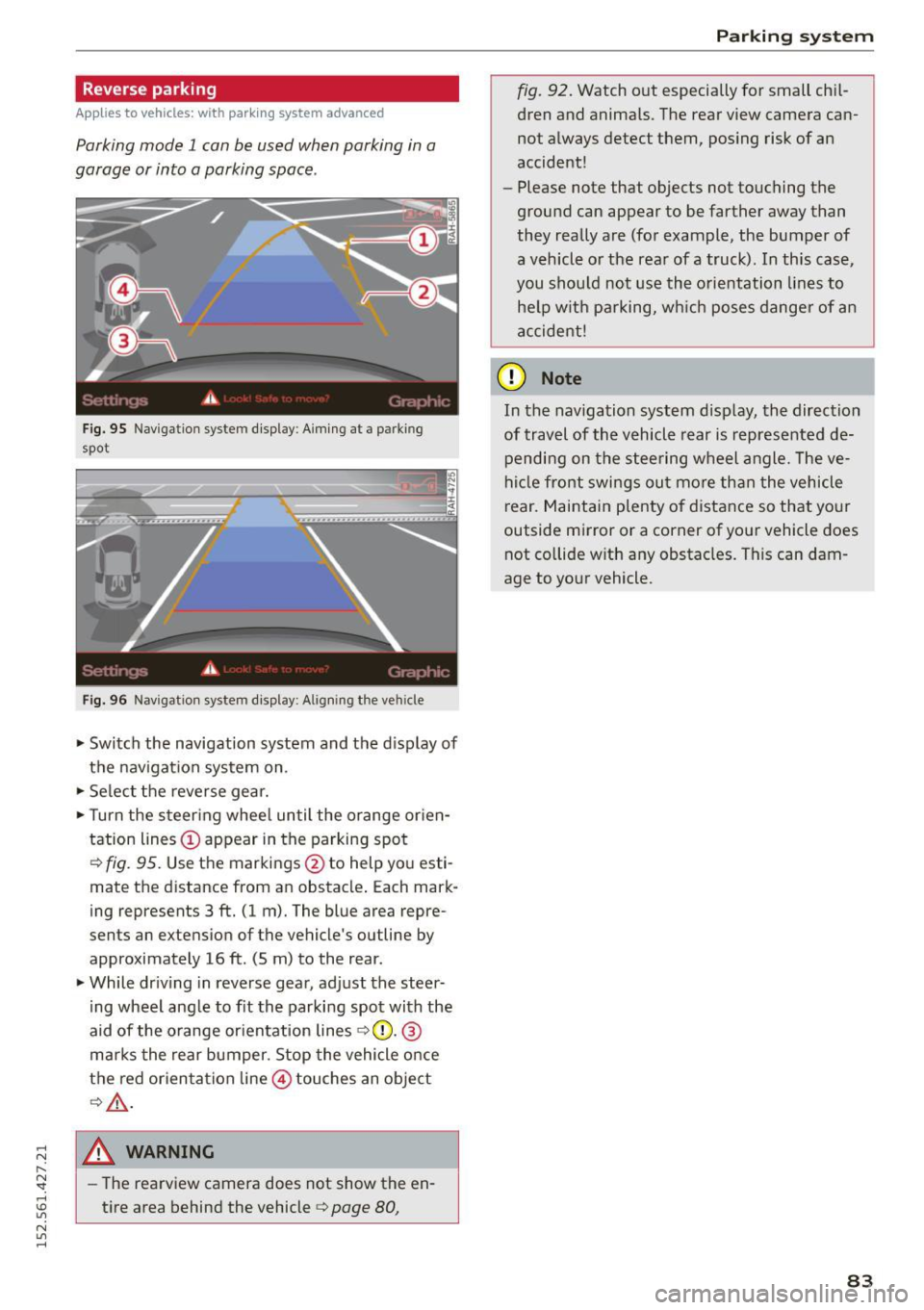
Fig. 95 Navigation system display : Aiming at a p arkin g
spot
Fig. 96 Naviga tion sy ste m display: Al ig ni ng t he ve hicle
"'Switch the navigation system and the display of
the navigation system on.
"'Select the reverse gear.
"'Turn the steering wheel until the orange orien
tation lines(!) appear in the parking spot
c> fig. 95. Use the markings @to help you esti
mate the distance from an obstacle. Each mark
ing represents 3
ft. (1 m). The blue area repre
sents an extension of the vehicle's outline by
approximately 16
ft. (5 m) to the rear .
"'While driving in reverse gear, adjust the steer
ing wheel angle to fit the parking spot with the
aid of the orange orientation lines
c> 0 . ®
marks the rear bumper. Stop the vehicle once
the red orientation line@ touches an object
¢&, .
_& WARNING
-The rearview camera does not show the en
tire area behind the vehicle
c> page 80,
Parking system
fig. 92. Watch out especially for small chil
dren and animals. The rear view camera can
not always detect them, posing risk of an
accident!
- Please note that objects not touching the
ground can appear to be farther away than
they really are (for example, the bumper of
a vehicle or the rear of a truck). In this case,
you should not use the orientation lines to
help with parking, which poses danger of an
accident!
(D Note
In the navigation system display, the direction
of travel of the vehicle rear is represented de pending on the steering wheel angle. The ve
hicle front swings out more than the vehicle
rear. Maintain plenty of distance so that your
outside mirror or a corner of your vehicle does
not collide with any obstacles. This can dam
age to your vehicle.
83