towing AUDI RS7 SPORTBACK 2014 Owners Manual
[x] Cancel search | Manufacturer: AUDI, Model Year: 2014, Model line: RS7 SPORTBACK, Model: AUDI RS7 SPORTBACK 2014Pages: 292, PDF Size: 73.56 MB
Page 5 of 292
Safet y fir st . . . . . . . . . . . . . . . . . . . . 123
Driving Safely . . . . . . . . . . . . . . . . . 123
General notes . . . . . . . . . . . . . . . . . . . . 123
Proper occupant seating posit ions . . . 124
Driver and passenger side footwell . . . 128
Pedal area . . . . . . . . . . . . . . . . . . . . . . . 128
Stowing luggage . . . . . . . . . . . . . . . . . 129
R eport ing Safety Defects . . . . . . . . . . . 13 1
Safety belts . . . . . . . . . . . . . . . . . . . 133
General notes . . . . . . . . . . . . . . . . . . . . 133
Why safety bel ts? . . . . . . . . . . . . . . . . 134
Safety belts . . . . . . . . . . . . . . . . . . . . . 136
Safety belt p re tens ioners . . . . . . . . . . 139
Airbag system . . . . . . . . . . . . . . . . . 142
I mpor tant th ings to know . . . . . . . . . . 1 42
Fr ont airbags . . . . . . . . . . . . . . . . . . . . 146
M onitoring the Advanced Airbag
System . . . . . . . . . . . . . . . . . . . . . . . . . 154
Knee airbags . . . . . . . . . . . . . . . . . . . . . 159
Side airbags . . . . . . . . . . . . . . . . . . . . . 162
Side curta in a irbags . . . . . . . . . . . . . . . 165
Ch ild Safety . . . . . . . . . . . . . . . . . . . 168
Important things to know .. .. .. .. . .
C hi ld safety seats ............ .... .
Install ing a chi ld safety seat .. .. ... .
L A TC H L ower ancho rages and tethe rs
fo r ch ild ren . ............. .... .. . .
Addit io nal Informa tion
Audi pre sense .......... .. .. . .
Pr even ta ti ve passe nger p rotec tion
Vehicle operation ....... .. .. . .
Intelligent technology .. .. .. . .
N ot ice about da ta re corded by vehi cle
con trol mo dules ... .... ... .. .. .. . .
Electronic Stabilization Control (ESC) .
Rear spoiler . ... ...... ... .. .. .. . .
Braking .. .. ................. .. . .
Electro-mechanical power assist,
dynamic steering .............. .. . 168
174
179
18 2
186
187
18 7
189
189
189
189
192
193
194
Table of contents 3
Driving with your q uattro . . . . . . . . . . 195
Energy management . . . . . . . . . . . . . . 195
Driving and environment . . . . . 198
The first 1,000 miles (1,500 km) and
afterwards . . . . . . . . . . . . . . . . . . . . . . 198
Avoid damaging the vehicle . . . . . . . . . 199
Driving throug h water on roads . . . . . 199
Warmi ng up and coo ling down . . . . . . 199
Catalytic co nverter . . . . . . . . . . . . . . . . 199
Sh utting down vehicle . . . . . . . . . . . . . 200
Operate your vehicle economically a nd
min imi ze poll ution . . . . . . . . . . . . . . . . 200
Vehicle care . . . . . . . . . . . . . . . . . . . 203
Vehicle care and cleaning . . . . . 203
Gener al informa tion . . . . . . . . . . . . . . 203
Car washes . . . . . . . . . . . . . . . . . . . . . . 203
Cleaning and care information . . . . . . 204
Fuel supply and filling your
fuel tank . . . . . . . . . . . . . . . . . . . . . . .
208
Gasoline . . . . . . . . . . . . . . . . . . . . . . . . 208
Fuel tank. . . . . . . . . . . . . . . . . . . . . . . . 209
Checking and filling . . . . . . . . . . . 213
Engine hood . . . . . . . . . . . . . . . . . . . . . 213
Engine compartment.............. 215
Engine oil . . . . . . . . . . . . . . . . . . . . . . . 215
Engine cooling system . . . . . . . . . . . . . 220
Brake fluid . . . . . . . . . . . . . . . . . . . . . . 222
Battery . . . . . . . . . . . . . . . . . . . . . . . . . 223
Windsh ie ld/headlight* washer
c ont ainer . . . . . . . . . . . . . . . . . . . . . . . 227
Tires and wheels . . . . . . . . . . . . . . 228
T ires . . . . . . . . . . . . . . . . . . . . . . . . . . . 228
T ire pressure mo nitor ing system 246
Do-it -yourself service . . . . . . . . . 2 50
What do I do now? ............ 250
E mergency warn ing triangle . . . . . . . . 250
Vehicle tool kit . . . . . . . . . . . . . . . . . . . 250
Tire repa ir . . . . . . . . . . . . . . . . . . . . . . . 251
Changi ng a wheel . . . . . . . . . . . . . . . . . 254
•
•
Page 6 of 292
4 Table of contents
Fuses and bulbs . . . . . . . . . . . . . . .
260
F uses. ..... ... . ...... ... .. .. .... 260
Bulbs. . . . . . . . . . . . . . . . . . . . . . . . . . . 263
Emergency situations . . . . . . . . . 264
General . . . . . . . . . . . . . . . . . . . . . . . . . 264
Starting by push ing or tow ing . . . . . . . 264
Starting with jumper cables . . . . . . . . 264
Use of jumper cab les . . . . . . . . . . . . . . 265
Eme rgency towing with commercial
tow truck . . . . . . . . . . . . . . . . . . . . . . . 266
Lift ing vehicle . . . . . . . . . . . . . . . . . . . . 268
Technical data . . . . . . . . . . . . . . . . . 270
Technical data . . . . . . . . . . . . . . . . . 270
Vehicle ident ifica tion . . . . . . . . . . . . . . 2 70
Weights . . . . . . . . . . . . . . . . . . . . . . . . 270
D imensions .... .. ..... ... .. .. ... . 271
Capacities . . . . . . . . . . . . . . . . . . . . . . . 271
RS 7 Sportback 4 .0, 8 cylinder . . . . . . 272
Consumer Information . . . . . . . 273
Warranty coverages . . . . . . . . . . . . . . . 273
Operating your vehicle o utside the
U.S.A . or Canada . . . . . . . . . . . . . . . . . 273
Audi Service Repair Manuals and Literature . . . . . . . . . . . . . . . . . . . . . . . 273
Maintenance .............. ... .. .. 273
Addit ional accessories, modifications
and parts replacement . . . . . . . . . . . . 275
D eclar ation o f Compliance,
Te lecommunication and Electronic
Systems . . . . . . . . . . . . . . . . . . . . . . . . 276
Inde x . . . . . . . . . . . . . . . . . . . . . . . . . . 27 7
Page 47 of 292
visibility conditions. For example, fog cannot be detected by the light sensors.
So always switch on the headlights 1§.D under these weather conditions and
when driving in the dark.
- Crashes can happen when you cannot see
the road ahead and when you cannot be
seen by other motorists . Always turn on
the headlights so that you can see ahead
and so that others can see your car from
the back.
- Please observe legal regulations when
using the light ing systems descr ibed .
(D Note
The rear fog lights should only be turned
on in accordance with traffic regulation, as
the lights are bright for following traffic.
@ Tips
- The light sensor* for automatic head light range control* is located in the rear
view mirror mount. You should therefore not apply any stickers to the windshield
in this area in order to prevent malfunc
tions or failures.
- In the event of a light sensor malfunc
tion, the driver is notified in the instru
ment cluster display
¢ page 22 .
-You will hear a warning tone if you open
the driver door when the exterior lights
are switched on .
- In cool or damp weather, the inside of
the headlights, turn signals and tail
lights can fog over due to the tempera
ture difference between the inside and
outside. They will clear shortly after
switching them on. This does not affect
the service life of the lighting .
Clear vision 45
Emergency flasher
The emergency flasher makes other motorists
aware that you or your vehicle are in an emer
gency situation .
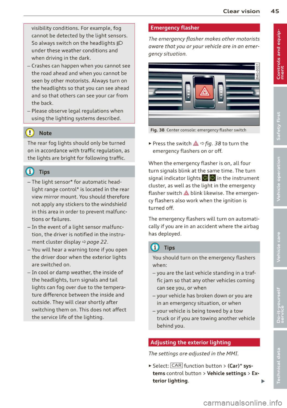
Fig. 38 Ce nt er co nsol e: em erge ncy flash er sw itc h
.,. Press the switch & ¢ fig. 38 to turn the
emergency flashers on or off.
When the emergency flasher is on, all four
turn signals blink at the same time . The turn
signal indicator lights
II Nin the instrument
cluster, as well as the light in the emergency
flasher switch
& blink likewise. The emergen
cy flashers also work when the ignition is
turned off.
The emergency flashers will turn on automati
cally if you are in an accident where the airbag has deployed.
@ Tips
You should turn on the emergency flashers
when:
- you a re the last vehicle standing in a traf
fic jam so that any other vehicles coming
can see you, or when
- your vehicle has broken down or you are
in an emergency situation, or when
- your vehicle is being towed by a tow
truck or if you are towing another vehicle
behind you.
Adjusting the exterior lighting
The settings are adjusted in the MMI .
.,. Select: !CAR ! function button> (Car)* sys
tem s
control button > Vehicle settings > Ex-
terior lighting. ..,.
Page 68 of 292
66 Seats and st o rage
Belts showing damage to webbing, bind
ings, buckles, or retractors must be re
placed.
(D Note
- If you move the front seat back when the
rear seat backrest is fo lded forward, you
could damage the head restraints on the
rear seat.
- Slide the belt guide on the outside safety
belt all the way up before folding the
backrest back forward. Make sure the
seat belt is not p inched or damaged
when the rear seat backrest if folded
back. Other objects shou ld be removed
from the rear seat bench to protect the
seatbac k from d amage.
Tie -downs and cargo net
The cargo net" prevents small objects from
sliding.
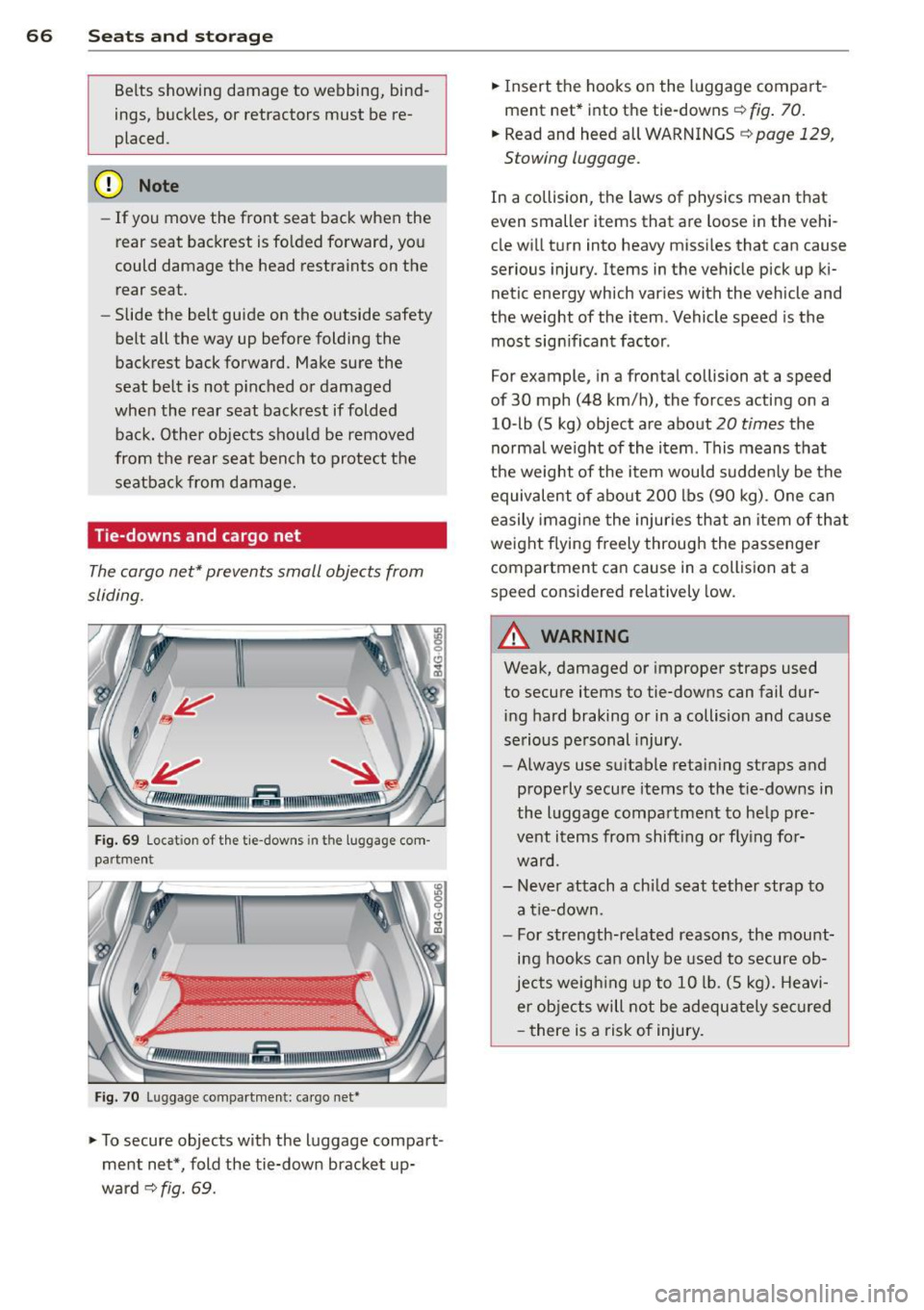
Fig . 69 Locat ion of the tie -downs in the luggage com
partment
Fig. 7 0 Luggage compartme nt: ca rgo net*
... To secure objects with the luggage compart
ment net*, fold the tie-down bracket up
ward
c:::> fig. 69.
... Insert the hooks on the luggage compart
ment net* into the tie-downs
c:::> fig. 70.
... Read and heed all WARNINGS c:::> page 129,
Stowing luggage.
In a collision, the laws of physics mean that
even smaller items that are loose in the vehi
cle will turn into heavy missi les that can cause
serious injury. Items in the vehicle pick up ki
netic energy which varies with the vehicle and
the weight of the item . Vehicle speed is the
most sign ificant factor .
For example, in a frontal collision at a speed
of 30 mph (48 km/h), the forces acting on a
10-lb (5 kg) object are about
20 times the
normal we ight of the item . This means that
the weight of the item would sudden ly be the
equivalent of abo ut 200 lbs (90 kg). One can
easily imagine the injuries that an item of that
weight flying freely through the passenge r
compartment ca n cause in a collision at a
speed considered relatively low.
A WARNING
-
Weak, damaged or improper straps used
to secure items to tie-downs can fail dur
ing hard braking or in a collision and cause
serious personal injury.
- Always use suitable retaining straps and
properly secure items to the tie-downs in
the l uggage compartment to help pre
vent items from shift ing or fly ing for
ward.
- Never attach a chi ld seat tether strap to
a tie-down.
- For strength-related reasons, the mou nt
ing hooks can only be used to secure ob
jects weigh ing up to 10 lb. (5 kg). Heavi
er objects will not be adequ ately sec ured
- there is a risk of injury.
Page 131 of 292
Floor mats used in your vehicle must be at
tached to these fast eners. Proper ly securing
the floor mats will prevent them from s lid ing
into positions that could interfere with the
pedals or impair safe operation of your vehicle
in other ways .
A WARNING
Pedals that cannot move freely can resu lt
in a loss of veh icle contro l and increase the
r isk o f se rious personal injury .
- Always make sure that floor mats are
properly secured.
- Never place or install floor mats or o ther
floo r coverings in the veh icle that cannot
be properly secured in pla ce to prevent
them from slipping and inte rfering w ith
the pedals or the ability to control the
vehicle.
- Never place o r inst all floo r ma ts or o ther
floo r coverings on top of already insta l
led floor mats. Additional floor mats and
other coverings wi ll reduce the size of
the pedal a rea and interfere with the
peda ls.
- Always properly reinstall and secure f loor
mats t hat have been taken out for clean
ing.
- Always make sure that ob jects cannot
fall into the driver footwe ll wh ile the ve
hicle is moving. Objects can become
t rapped under the brake pedal and accel
erator peda l causing a loss of veh icle
control.
Stowing luggage
Loading the luggage compartment
All luggage and other objects must be prop
erly stowed and secured in the luggage com
partment.
L oose items in the luggage compar tment can
shift suddenly , changing vehicle hand ling
characterist ics. Loose items can also increase
the r isk of se rious personal injury in a sudden
vehicle maneuve r or in a collision .
Driving S afel y 129
.. Distribute the load evenly in the l uggage
compa rtment .
.. Always place and proper ly secure heavy
items in the luggage compartment as fa r
forward as possible .
.. Secure luggage using the tie -downs p rov id
ed
c:> page 64, Luggage compartment.
.. Make s ure that the rear seatback is securely
la tched in place.
A WARNING
I mproperly store d luggage or other items
can fly t hro ugh the ve hicle causing ser ious
personal injury in the event of hard brak
ing or an accident. To help reduce the risk
of ser ious persona l injury:
- Always put objects, for exam ple, luggage
or other heavy items in the luggage com
partment.
- Always secure objects in the luggage
compartment using the t ie-down hoo ks
a nd suitable straps.
A WARNING
Heavy loads w ill influence the way yo ur ve
h icle handles . To help reduce the risk of a
loss of cont ro l leading to serious pe rsonal
injury :
- Always keep in mind when transporting
heavy objects, that a change in the cen
ter of gravity can also cause changes in
veh icle han dling:
- Always distribute the load as evenly as
possible.
- Place heavy objects as far forward in
the luggage compartment as possible.
- Never exceed the Gross Axle Weight Rat
ing or the G ross Vehicle We ight Rating
specified on the sa fety comp liance stick
er on the left door jamb. Exceeding per
miss ible weight standards can cause the
ve hicle to slide and hand le different ly .
- Please observe informat ion on safe dr iv
ing
c:>page 123.
•
•
Page 239 of 292
pressure label) c> page 232,
fig. 195.
2. Determine the combined
weight of the driver and passengers that will be riding in
your vehicle.
3. Subtract the combined
weight of the driver and pas s engers from
"XXX" kilo
grams or
"XXX" pounds
s hown on the sti cker
c> page 232 , fig. 195.
4. The resulting figure equals
the available amount of car go and luggage load capa ci
ty . For example , if the
"XXX"
amount equals 1400 lbs .
and there will be five 150 lbs. passengers in your vehi
cle, the amount of available
cargo and luggage load ca
pacity is 650 lbs. (1400-750
(5
X 150) = 650 lbs.)
5. Determine the combined weight of luggage and cargo
being loaded on the vehicle.
That weight may not safely exceed the available cargo
and luggage load capacity
calculated in Step 4.
6. If your vehicle will be towing
a trailer, load from your trail
er will be transferred to your
Tires and wheels 237
vehicle . Consult this manual
to determine how this re
duce s the available cargo
and luggage load capacity of
your vehicle .
.,..Check the tire sidewall
(¢ page 239, fig. 199) to de
termine the designated load rating for a specific tire.
Tire service life
The servic e lif e of tires dep ends on a lot of
d ifferen t things inclu ding p roper ins tall ation
a n d ba lanc in g, corre ct ti re press ure and dr iv
ing style .
Fig. 197 Tire trea d: tread wea r in dicators (TWI)
,.............,------,,
-=---::;:-r-
Fig. 198 Rotat ing tires for more even wear
Tread Wear Indicator (TWI)
The or iginal tires on you r vehicle h ave
1/ 16 inch ( 1.6 mm) hi gh "wear indicato rs"
r::!> fig. 197 run ning acr oss the tread. Depen d-
ing on the mak e, th ere will be si x to eight of
t h em evenly placed a ro und t he tire. Marks on
the tire sidewall (for e xamp le ''TWI" or ot her
Ill>
Page 252 of 292
250 What do I do now?
What do I do now?
Emergency warning
triangle
App lies to vehicles: with emerge ncy warning triangle
The warning triangle is located on the inside
of the trunk lid .
-
"' M ~ 0 6
~ ~
Fig. 203 Trunk lid: Warning triang le
.,. To open the cover, turn the locking mecha
nism and pull the cover downward .
" m
.,. Remove the warning triang le from its hold
er .
The rear lid is only designed to hold the warn
ing triangle offered by the original accessories
program. If you would like to retrofit your ve
hicle with a warning triangle, p lease contact
your authorized Audi dealer.
Vehicle tool kit
Vehicle tool kit and jack
The vehicle tool kit is located in the luggage
compartment under the cargo floor cover.
Fig. 204 Trunk lid: V ehicl e too l kit
.,. Fold the floor to the seatback with the help
of the handle . .,.
Turn the handwheel counter-clockwise and
remove the cover to reach the veh icle tool
kit.
T he onboard tool kit includes :
- Tire repair kit (Tire Mobility System)
- Hooks to remove the wheel covers*
- Plastic hook to remove wheel bolt covers*
- Wheel bolt wrench
- Alignment pin for changing wheels
- Screwd river with reversible bla de
-Towing eye
-J ack
Before storing the jack, make sure it is wound
back down as far as it will go .
A WARNING
Improper use of the vehicle jack can cause
serious personal injuries.
- Never use the screw driver hex head to
tighten wheel bolts, since the bolts can
not attain the necessary tighten ing tor
que if you use the hex head, potentially
causing an accident .
- The factory-supplied jack is intended on
ly for your vehicle model. Under no cir
cumstances should it be used to lift
heavy veh icles or other loads; you risk in
juring yourself.
- Never start the engine when the vehicle
is raised, which could cause an acc ident.
- Support the vehicle securely with appro
priate stands if work is to be performed
underneath the vehicle; otherwise, there
is a potential risk for injury.
- Never use the jack supplied with your
Audi on another vehicle, particularly on a
heav ier one. The jack is only suitable for
use on the veh icle it came with.
@ Tips
- Some of the onboard items listed above
are provided on certain models only or
are optional extras .
- Before you can raise your vehicle using
the jack, you must activate the jacking
mode¢
page 256 .
Page 266 of 292
264 Emergency situations
Emergency situations
General
This chapter is intended for trained emer
gency crews and working personnel who
have the necessary tools and equipment to
perform these ope rations.
Starting by pushing or
towing
Q;) Note
Vehicles w ith an automatic transmission
cannot be started by pus hing o r tow ing.
Starting with jumper
cables
If necessary, the engine can be started by
connecting it to the battery of another vehi
cle.
If the engine should fail to start because of a
discharged or weak battery, the battery can be
connected to the battery of
another veh icle,
using a
pair of jumpe r cables to start the en
g ine .
Jumper cables
Use only jumper cables of sufficiently large
cross section to carry the starter current safe
ly. Refer to the manufacturer's specif ications.
Use only jumper cables with
insulated termi
na l clamps which are distinctly marked:
plus(+) cable in most cases colored red
minu s(-) cable
in most cases colored black .
A WARNING
Batteries contain electricity, acid, and gas.
Any of these can cause very serious or fatal
inju ry. Follow the instructions below for
safe handling of your veh icle's battery.
- Always shield you r eyes and avoid lean
ing over the battery whenever possible.
- A discharged battery can freeze at tem
peratures just be low 32 °F (0 °C). Before connecting a
jumper cable, you must
thaw the frozen battery complete ly, oth
erwise it could explode.
- Do not allow battery acid to contact eyes
or skin. Flush any contacted area with
water immediately.
- Improper use of a booster battery to start a vehicle may cause an explosion.
- Vehicle batteries generate explosive gas
es. Keep sparks, flame and lighted ciga
rettes away from batteries.
- Do not try to jump start any vehicle with a low acid level in the battery.
- The vo ltage of the booster battery must
also have a 12-volt rating. The capacity
(Ah) of the booster battery should not be
lower than that of the discharged bat
tery . Use of batteries of d ifferent voltage
or substantially different "Ah" rating
may cause an exp losion and personal in
jury.
- Never charge a frozen batte ry. Gas trap
ped in the ice may cause an explosion.
- Never charge or use a battery that has
been frozen. The battery case may have
be weakened.
- Use of batter ies of different voltage or
substantially different capacity (Ah) rat
ing may cause an exp losion and injury.
The capacity (Ah) of the booster battery
should not be lower than that of the dis
charged battery.
- Before you check anything in the engine
compartment, always read and heed a ll
WARNINGS¢
page 213.
(D Note
- App lying a higher voltage booster bat
tery will cause expensive damage to sen
sitive electronic components, such as
control units, relays, radio, etc.
- Th ere must be no electrical contact be
tween the vehicles as otherwise current cou ld already start to f low as soon as the
positive(+) terminals are connected. .,.
Page 268 of 292
266 Emergency situations
-When connecting jumper cables, make
sure that they cannot get caught in any
moving parts in the engine compart
ment .
- Before you check anything in the engine
compartment, always read and heed all
WARNINGS
<=) page 213.
(D Note
Improper hook-up of jumper cables can ru
in the generator.
- Always connect POSITIVE( +) to POSI
TIVE(+), and NEGATIVE(-) to NEGATIVE
( - ) ground post of the battery manager
control unit .
- Check that all screw plugs on the battery
cells are screwed in firmly . If not, tighten
plugs prior to connecting clamp on nega
tive battery terminal.
- Please note that the procedure for con
necting a jumper cable as described
above applies specifically to the case of
your vehicle being jump started. When
you are giving a jump start to another ve
hicle, do
not connect the negat ive( -) ca
ble to the negative( -) terminal on the
discharged battery ©
Q fig. 220. In
stead, securely connect the negative( -)
cable to either a solid metal component
that is firmly bolted to the engine block
or to the engine block itself. If the bat
tery that is being charged does not vent
to the outside, escaping battery gas
could ignite and explode!
Emergency towing
with commercial tow
truck
General hints
Your Audi requires special handling for tow
tng .
The following information is to be used by
commercia l tow truck operators who know
how to operate their equipment safely.
-Never tow your Audi. Towing will cause
damage to the engine and transmission .
- Never wrap the safety chains or winch ca
bles around the brake lines.
- To prevent unne cessary damage, your Audi
must be transported with a flat bed truck.
- To load the vehicle on to the flat bed, use
the towing loop found in the vehicle tools
and attach to the front or rear anchorage
r=) page 266 and ¢ page 267.
.&_ WARNING
=
A vehicle being towed is not safe for pas-
sengers. Never allow anyone to ride in a
vehicle be ing towed, for any reason.
Front towing loop
Only install the front towing loop when it is
needed.
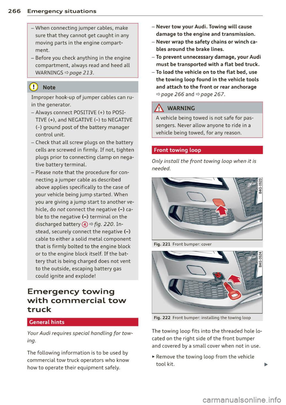
Fig. 221 Front bumpe r: cove r
Fig. 222 Front bumper: installing the towing loop
-
The towing loop fits into the threaded hole lo
cated on the right side of the front bumper
and covered by a smal l cover when not in use.
.,. Remove the towing loop from the vehicle
tool kit.
Page 269 of 292
.. Press the cover in by applying short strong
pressure to the bottom part to release it
from the bumper
¢ fig. 221 .
.. Screw the towing loop in the threaded open-
ing and tighten it until it stops
¢fig. 222.
Remove the towing loop when you are done
using it and place it back in the vehicle tool
kit. Install the cover in the bumper. Always
keep the towing loop in the vehicle.
A WARNING
If you do not screw the tow ing loop com
pletely, it could come out of the threaded
hole while the vehicle is being towed cau s
ing damage to the vehicle and possib le se
r ious personal inju ry.
Rear towing loop
Only install the rear towing loop when it is
needed.
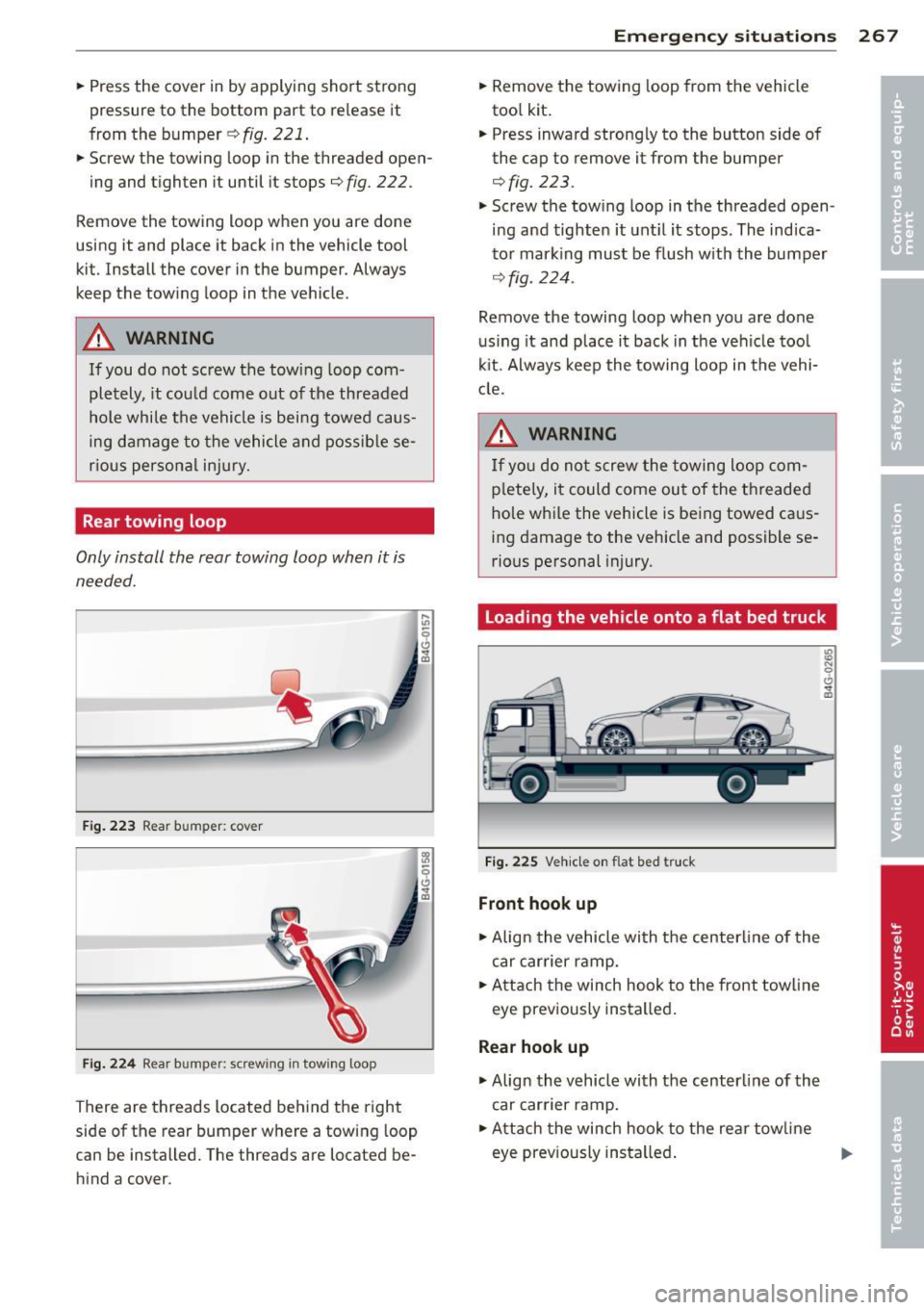
F ig. 223 Rear bumper: cover
Fi g. 2 24 Rear bumper: screwing in towing loop
There are threads located behind the right
side of the rear bumper where a towing loop
can be installed. The threads are located be
hind a cover.
Emergenc y situ ation s 267
.. Remove the tow ing loop from the vehicle
too l kit .
.. Press inward strongly to the button side of
the cap to remove it from the bumper
¢fig. 223.
.. Screw the towing loop in the threaded open
ing and tighten it unt il it stops. The indica
to r mark ing must be flush w ith th e bumper
¢fig. 224.
Remove the towing loop when you are done
using it and place it back in the veh icle too l
ki t. Always keep the towing loop in the vehi
cle.
A WARNING
If yo u do not screw the towing loop com
p letely , it co uld come out of the t hreaded
hole while the vehicle is being towed caus
ing damage to the vehicle and possible se
rious pe rsonal injury.
loading the vehicle onto a flat bed truck
Fi g. 225 Vehicle on flat bed tru ck
Front hook up
.. Align the vehicle with t he centerline of the
car car rier ramp .
.,. Attach the winch hook to the front towline
eye prev iously insta lled .
Rear hook up
.,. Align the vehicle with the center line of the
car carrier ramp .
.. Attach the winch hook to the re ar tow line
eye prev ious ly insta lled .
u,