technical data AUDI S3 2011 Owners Manual
[x] Cancel search | Manufacturer: AUDI, Model Year: 2011, Model line: S3, Model: AUDI S3 2011Pages: 320, PDF Size: 75.79 MB
Page 285 of 320
_______________________________________________ F_u _s_ e_ s_ a_ n_ d_ b_u _ l_ b _ s __ _
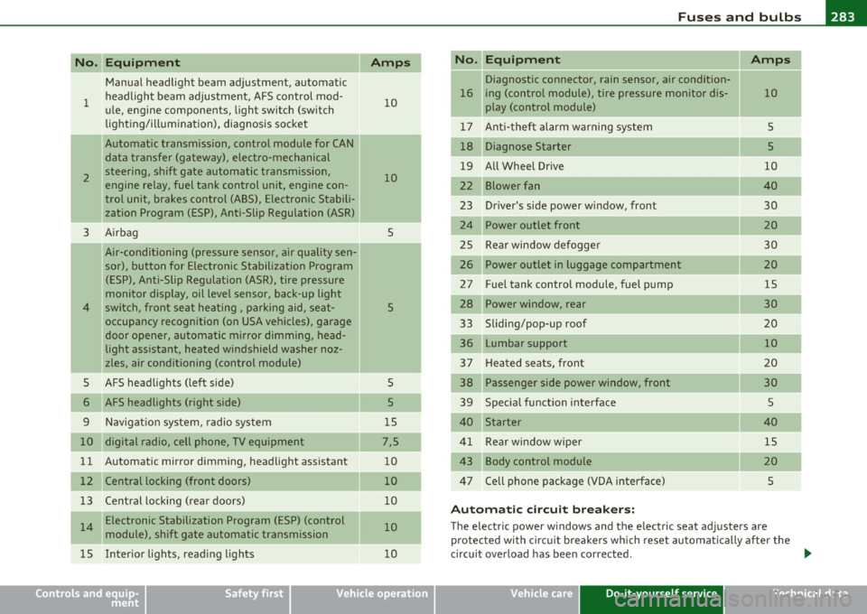
Equipment No. II Equipment
Amps
Manual headlight beam adjustment, automatic Diagnostic connector, rain sensor, air condition-
headlight beam adjustment, AFS control mod-
16 ing (control module), tire pressure monitor dis-10
1 ule, engine components, light switch (switch 10 play (control module)
-lig hti ng/i llum i nation), diagnosis socket 1 7 Ant i-theft alarm warning system 5
Automatic transmission, control module for CAN 18 Diagnose Starter 5
data transfer (gateway), electro-mechanical
19 All Whee l Drive 10 steering, shift gate automatic transmission, 2 10 engine relay, fuel tank control unit, engine con-22 Blower fan 40
trol unit, brakes control (ABS), Electronic Stabili-23 Driver's side power window, front 30 zation Program (ESP), Anti-Slip Regulation (ASR)
3 Airbag 5 24 Power outlet front 20
Air-conditioning (pressure sensor, air quality sen-25 Rear window defogge r 30
sor), button for Electronic Stabilization Program 26 Power outlet in luggage compartment 20
(ESP), Anti-Slip Regulation (ASR), tire pressure 27 Fuel tank control module, fuel pump 15
monitor display, oil level sensor, back-up light
28 Power window, rear 30 4 switch, front seat heating, parking aid, seat-s
occupancy recognition (on USA vehicles), garage 33 Sliding/pop-up roof 20
door opener, automatic mirror dimming, head-
Lumbar support
10 light assistant, heated windshield washer noz-
zles, air conditioning (control module)
3 7 Hea ted seats, front 20
--
5 AFS headlights (left side) 5 38 Passenger side power window, front 30
AFS headlights (right side) 5 39 Specia l function interface 5
9
Navigat ion system, radio system 15 40 Starter 40
digital radio, cell phone, TV equipment 7,5 Rear window wiper 15
11
Automatic mirror dimming, headlight assistant 10 Body control module 20
12 Central locking (front doors) 10 47 Ce ll phone package (VDA interface) 5
13
Central locking (rear doors) 10
A uto m atic c ircu it bre ake rs :
14 Electronic Stabilization Program (ESP) (control 10 The electric power w indows and the electric seat adjusters are
module), shift gate automatic transmission protected with circuit b reakers which reset automatically after the
1 5 Inter ior lights, read ing lights 10 circuit overload has been corrected . ...
Safety first Vehicle care Do-it-yourself service Technical data
Page 287 of 320
_______________________________________________ F_u _s_ e_ s_ a_ n_ d_ b_u _ l_ b _ s __ _
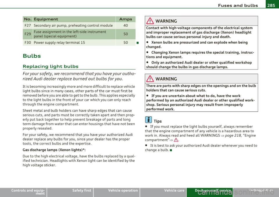
No. Equipment
F2 7 Secondary a ir pump, preheating contro l module
F 29 Fuse assignment in the left-side instrument
panel (special equipment)
F30 Power supply relay termina l 15
Bulbs
Replacing light bulbs
Amps
40
so
so
For you r safety, we recommend that you have your autho
ri zed Audi dealer replace burned out bulbs for you.
It is becoming increasingly more and more difficu lt to rep lace vehicle
light bulbs since in many cases, ot her parts of the car must first be
removed before you are able to get to the bu lb. This app lies espec ially
to the l igh t bu lbs in the front of your car whi ch you can o nly rea ch
through the engine compartment .
Sheet metal and bu lb holders can have sharp edges that can ca use
serious cuts, and parts must be correctly taken apart and the n prop
erly put back together to he lp prevent b reakage of parts and long
term damage from wate r that can enter housings that have not been
p roperly resealed.
For your safety, we recommend that you have you r authorized Audi
deale r replace any bu lbs fo r you, since your dealer has the proper
too ls, the cor rec t bu lbs and the expertise .
Gas dis charge lamp s (Xenon lights)* :
Due to the high electrical voltage, have the bulbs replaced by a qual
ified technician. Headlights with Xe non light can be iden tified by the
high voltage sticker.
Safety first
•
& WARNING
C ontact with high-voltag e components of the electrica l system
and improper replacement of g as discharge (Xenon ) headlight
bulb s can caus e serious personal injury and death .
• Xenon bulb s are pres surized and can explode when b eing
c hanged .
• Changing Xenon lamp s requir es the special training , instruc
tions and equipment.
• Only an authori zed Audi dealer or oth er qualified workshop
should change the bulbs in ga s di scharge lamp s.
& WARNING
There are parts with sharp edge s on the openi ngs and on the bulb
holde rs that can cau se se rious cuts.
• If you are uncertain about what to do, ha ve the work
performed b y an auth orized Audi de aler or oth er qualified work
s hop. Seriou s per sonal injur y m ay re sult from improperl y
p erformed w ork.
(I] Tips
• If you must replace the light bulbs yourself , a lways remember
that the engine compar tment of any vehicle is a hazardo us area to
work in. Always read and heed all WARNINGS=>
page 218, "E ngi ne
compa rtment" =>& .
• It is best to ask you r author ized Audi dealer whenever you need to
change a bu lb. •
Vehicle care Do-it-yourself service Technical data
Page 289 of 320
_____________________________________________ E_ m_ e_r-= g ::.. e_ n_c-= y'- s_ i_t _u _a_ t_ i_ o _ n_ s __ fflll
& WARNING (co ntinued )
• Before you che ck anything in the engine compartment , alway s
r e ad and heed all WARNINGS =>
page 218, "Engi ne compart
ment ".
0 Note
• App lying a higher vo ltage booster battery will cause expens ive
damage to sens itive e lec tro nic components, such as contro l units,
re lays, rad io, etc.
• Th ere must be no electrical contact between the veh icles as othe r
wise current could a lready sta rt to flow as soon as the posit ive(+)
term inals are con nected.
• Improperly connecte d jumper cables can cause substantial
damage to the e lectr ica l system of the vehicle .
[I) Tips
• The discharged batte ry mu st be properly co nne cted to the
vehicle's elect rical system. •
General information of starting
assistance
Please observe that the procedure descr ibed below for connect ing
jumpe r cab les is intended to p rovide a ju mp s tart for your ve hicl e.
Make sure t hat the co nnected clamps have suff ic ient
metal contact.
Sta rt assistance differs for vehicles w ith a 4-cylinde r engine:
=> page 288, "Use of jumper cables"
Safety first
& WARNING
Improper handling of the jumper cables can lead to an explosion
of the battery and severe injurie s. To reduce the ri sk of injury, note
the following:
• The section s of the terminal clamps that are not insul ated
must not touch each other. In addition, the cable clamped to the
battery' s po sitive terminal must not come in contact with electri
cally connected parts of the veh icle -danger of short circu it!
• Route the jumper cable so that it cannot catch in any rotating
parts in the engine compartment .
• Do not bend over the batteries -danger of chemical burns!
• The battery cell locking screws must be tightened securely.
• Keep ignition source s (open flame , burning cigarettes, etc.)
away from the batteries -danger of explosion!
• Do not clamp the minus cable to parts of the fuel system or the
brake lines.
0 Note
If you prov ide sta rt assistance for others with your vehi cle, you shou ld
not clamp the minus cable( -) to the negative te rm inal of the
discharged batte ry =>
page 288, fig. 19 7 © but to a solid metal part
sc rewed firm ly to the eng ine b lock, or to the e ng ine block itse lf . In
case of an inadequately venti lated battery o f the veh icle receiving
powe r, the re is a dange r of explosi on du e to detonat ing gas! •
Vehicle care Do-it-yourself service Technical data
Page 291 of 320
_____________________________________________ E_ m_ e_r-= g ::.. e_ n_c-= y'- s_ i_t _u _a_ t_ i_ o _ n_ s __ _
13. Disconnect the cable w hile the engine is runn ing exactly
in
reverse or der to t hat described in~ page 288,
"Connec ting/discon nect ing the jumper cable" . When
doi ng so , ma ke sure that t he cab le ca nnot contact rotat ing
eng ine parts .
14 . T urn the h eater bl ower a nd th e re ar w indow hea tin g off
a gain.
Th e bat tery is ven ted to the o utsi de to p reven t ga ses from en ter ing
the ve hicle interior .
M ake s ure that the jumpe r clamps a re well connected w ith their
metal parts in full contact with t he battery termi na ls .
& WARNING
To avoid serious personal injury and damage to the vehicle, heed
all warnings and instructions of the jumper cable manufacturer . If
in doubt, call for road service.
• Jumper cable s mu st be long enough so that the vehicles do not
touch.
• When connecting jumper cable s, make sure that they cannot
get caught in any moving parts in the engine compartment.
• Before you check anything in the engine compartment, always
read and heed all WARNINGS=>
page 218, "Engine compart
ment ".
0 Note
Im pro perly con ne cte d jum per c abl es c an dam age or destroy the
generator.
• Do not use the ba ttery nega tive term inal for jum p star ting or a
ma lf u nction co uld occ ur in the vehicle electrica l system .
• Always co nnect POSITIV E(+) to POSI TIVE( +), a nd NEGATIVE( -)
to N EGATIVE{ -) termina l.
Safety first
• Check that all screw p lugs on the battery cells are screwed in
fir mly . If no t, tig hten plugs pr ior to connectin g clamp o n negative
battery term inal.
• P lease note that the pr ocedur e fo r connecting a jumper cable as
described above app lies specifically to the case of your vehicle being
jum p st ar te d . When you are giving a jump start to anot her vehi cle, do
not conn ect the m in u s (-) cable to t he minus( -) term inal on the
discharged battery ©=>
page 288, fig. 197 . In stea d, sec urely
connect the mi nus( -) cable to either a massive metal component
that is f irm ly bo lte d to t he eng ine block or to the engine bloc k itse lf .
If the battery that i s bei ng charged does not ven t to t he ou tside,
escaping battery gas could ignite and explode! •
Emergency towing with
commercial tow truck
c;eneral hints
Your Audi requires s pecial h andling for to win g.
The follow ing informat ion is to be used by commercial tow truck
oper ator s w ho know how to oper ate th eir equipmen t sa fe ly.
• Never tow your Audi, towing will cause damage to the engine
and transmission.
• Never wrap the safety chains or winch cables around the brake
lines.
• To prevent unnecessary damage, your Audi must be transported
with a car carrier (flat bed truck ).
• To load the vehicle on to the flat bed, use the towing loop found
in the vehicle tools and attach to the front or rear anchorage
=> page 290 and=> page 290 . ..
Vehicle care Do-it-yourself service Technical data
Page 293 of 320
_____________________________________________ E_ m __ e_r-=g =- e_ n_c -==y "- s_i_ t _u _a _ t_ i_ o _ n_ s _ __.fflll
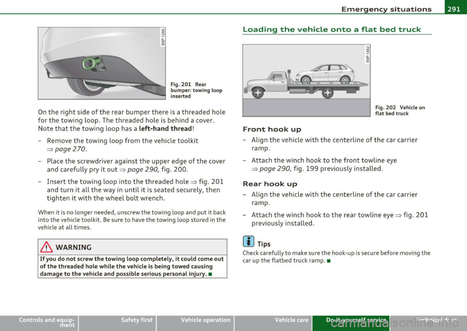
Fig. 201 Rear
bumper: towing loop
inserted
On the right side of the rear bumper there is a threaded hole
for the towing loop. The threaded hole is behind a cover.
Note that the towing loop has a
left-hand thread!
Remove the towing loop from the vehicle toolkit
=> page 270.
Place the screwdriver against the upper edge of the cover
and carefully pry it out :::>
page 290, fig. 200.
- Insert the towing loop into the threaded hole=> fig. 201
and turn it all the way in until it is seated securely, then
tighten it with the wheel bolt wrench.
When it is no longer needed, unscrew the towing loop and put it back
into the vehicle toolkit. Be sure to have the towing loop stored in the
vehicle at all times.
& WARNING
If you do not screw the towing loop completely, it could come out
of the threaded hole while the vehicle is being towed causing
damage to the vehicle and possible serious personal injury. •
Vehicle OP-eration
Loading the vehicle onto a flat bed truck
Front hook up
N (0 :? 0:. CD
"'
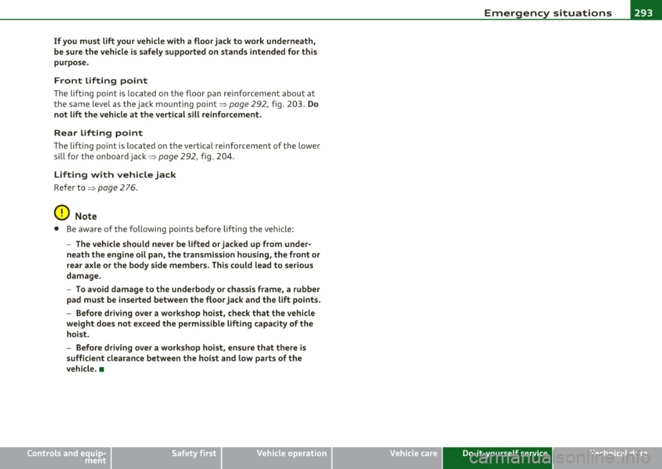
Fig. 202 Vehicle on
flat bed truck
- Align the vehicle with the centerline of the car carrier
ramp.
- Attach the winch hook to the front towline eye
=>
page 290, fig . 199 previously installed .
Rear hook up
-Align the vehicle with the centerline of the car carrier
ramp.
- Attach the winch hook to the rear towline eye=> fig. 201
previously installed.
rn Tips
Check carefully to make sure the hook-up is secure before moving the
car up the flatbed truck ramp. •
Vehicle care Do-it-yourself service iTechnical data
Page 295 of 320
_______________________________________________ E_ m_ e_r_, g::;._ e_n _ c""' y:.- s_ it_u_ a_t _ i_o _n_ s __ _
If you must lift your vehicle with a floor jack to work underneath,
be sure the vehicl e is safely supported on stand s intended for this
purpo se .
Front lifting point
The lifting point is located on the floor pan reinforcement about at
t he s ame leve l as the jack mo unting point~
page 292, fig. 2 03. Do
not lift the vehicle at th e vertical sill re inforcement.
Rear lifting point
The lifting po int is located on the ve rtical reinforcement of the lower
sill fo r the onboard ja ck ~
page 29 2, fig. 2 04.
Lifting with vehicle jack
Refe r to ~ page 2 76 .
0 Note
• Be aware of the following points before lifting the vehicle:
- The vehicle should never be lifted or jacked up from under
neath the engine oil pan , the tran smission housing , the front or
rear axle or the body side members. This could lead to serious
damage.
- To avoid damage to the underbody or chassis frame, a rubber
pad must be inse rted between the floor ja ck and the lift points.
- Before dr iving ov er a workshop hoist , check that the vehicle
weight does not exceed the permissible lifting capacity of the hoist.
- Before driving over a work shop hoi st, en sure that there is
sufficient clearance between the hoist and low parts of the
vehicle. •
Safety first Vehicle care Do-it-yourself service Technical data
Page 296 of 320
.,,___G_ e_ n _ e_ r_ a_ l_i_n _f_o _ r_ m __ a_t _ i_o _n _______________________________________________ _
General information
Explanation of technical data
Some of the technical data listed in this manual requires
further explanation.
The technical data for your vehicle is listed in the charts starting on
~ page 296. This sect ion prov ides genera l information, notes and
restrictions which app ly to this data .•
Veh icle identification
The key data are given on the vehicle identification
number (VIN) plate and the vehicle data sticker .
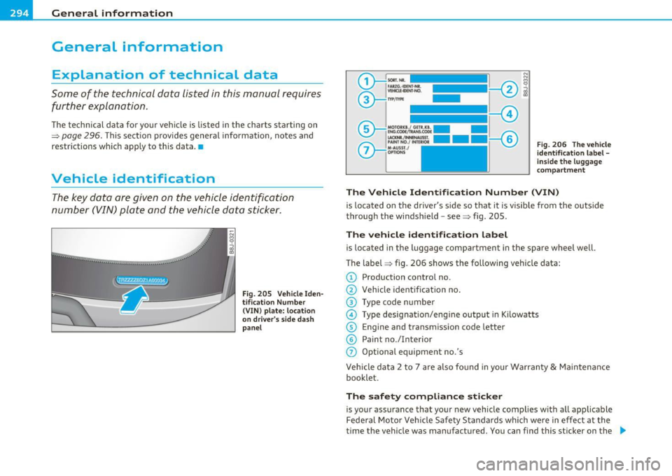
Fig. 20 5 Vehi cle I den
t ifi ca tion Nu mbe r
(VIN) pla te : loc atio n
o n d rive r's sid e d ash
p an el Fi
g. 2 06 Th e vehicle
identi ficati on l abel -
in side the l ugga ge
co mpa rtme nt
The Vehicle Ident ifi cat ion Number (VIN)
is located on the dr iver's s ide so that it is visible from the outside
through the windsh ield -see~ fig. 205 .
The vehicle identificati on label
is located in the luggage compartment in the spare wheel well.
The labe l~ fig. 206 shows the following vehicle data:
© Production control no.
@ Vehicle identification no.
@ Type code n umber
© Type designat io n/eng ine output in Kilowatts
© Engine and transmiss ion code letter
© Paint no./Interior
0 Optional equipment no.'s
Vehicle data 2 to 7 are also found in your Warranty & Maintena nce
booklet.
The safety comp liance stick er
is your assurance that your new vehicle complies w ith all applicable
Federal Motor Veh icle Safety Standa rds which we re in effect at the
time the vehicle was manufactured. You can find this sticker on the ._
Page 297 of 320

________________________________________________ G ..... e_ n_e ___ ra ___ l_i_n _ f_ o ___ r_m :....:....: a ..... t ..... i...: o ..... n---- --
left door jamb . It shows the month and year of production and the
vehicle iden tifica tion n umber of your veh icle ( perfo ration) as well as
the Gross Vehicle Weight Rating (GVWR) and the Gross Axle Weight Rating (GAWR).
The high voltage warning label
is loca ted on the loc k carr ier .
The spark ignition system complies with the
Canadian standard ICES-002. •
Weights
Gross Vehicle Weight Rating
The Gross Vehicle Weight Rating (GVWR), and the Gross Axle Weight
Ra ting (GAWR) for fron t and rear are listed on a st icker on the left
door jamb.
Th e Gross Vehicle Weight Rating includes the weight of the basic
vehicle plus f ull fue l tank, oil and coo la nt, plus max im um load, which
includes passenger we ight (150 lbs/68 kg per des ignated seating
position) a nd luggage weight .
Gross Axle Weight Rating
The Gross Axle Weight Rating is the maximum load that can be
applie d at each axle of the vehicle~& .
Vehicle capacity weight
The vehicle capacity weight (max. load) is liste d either o n the driver's
side B -pillar or inside the fuel f iller flap .
Roof weight
The maximum permiss ible roof weight is 165 lb (75 kg ). The roof
we igh t is ma de up o f the weig ht of the roof rack sys tem and the
we ight of the object being transported~
page 88, "Load ing the roof
rack" .
Safety first
& WARNING
• The actual Gross Axle Weight Rating at the front and rear axles
s hould not exceed the permis sible weights, and their combination
must not exceed the Gross Vehicle We ight Rating.
• Exceeding permi ssible weight rating s can result in vehicle
damage, accidents and personal injury .
0 Note
• The vehicle capac ity we ight figu res apply when the load is distrib
uted evenly i n the vehicle (passengers and luggage). When trans
porti ng a heavy load i n the l uggage compartment, ca rry the load as
near to the rear axle as possible so that the veh icle's handling is not
impa ired.
• Do not exceed the maximum permiss ible axle loads or the
maximum gross vehicle weig ht. Always remember that the vehicle's
hand ling will be affecte d by the extra load. Therefore, adjust your
speed a ccording ly .
• Always observe loca l reg ulations. •
Dimensions
The specifications refer to the basic mo de l. Differences may occur
depend ing on the model ty pe a nd options ordered, for exam ple, tir e
sizes .
0 Note
When d riving up steep ramps, on rough roads, over c urbs, etc . it is
impo rtan t to remember that some parts of yo ur vehicl e, s uch as
spoilers or ex haust system components, may be close to the ground.
B e careful not to d amage them .•
Do-it,yourself service Technical data
Page 299 of 320

_________________________________________________ D_a_ t_ a __ B'I
- Reserve (of total capacity)
Windshield washer fluid container
Engine oil with filter change
Safety first ga
l/liters
qu arts/liters
q uarts/liters 1.8 / 7 .0
3.1 / 3 .0
4. 8 I 4.6
Do-it,yourself service
•
Technical data
Page 301 of 320
____________________________________________ ...;C _o_ n_s ...;u_ m __ e_r_ I _n_ f...;o _r_ m..:....:...: a:.:. t..:...:..; io:..:.... n __ _
Consumer Information
Warranty coverages
Your Audi i s covered by the following warrantie s:
• New Vehicle Limited Warranty
• Limited Warranty Against Corrosion Perforation
• Emissions Control System Warranty
• Emissions Performance Warranty
• California Emissions Control Warranty (USA vehicles only)
• California Emissions Performance Warranty (USA vehicles only)
Detailed in forma tion reg ard ing yo ur war ran ties can be fo und in your
Warranty & Maintenance Booklet .•
Operating your vehicle outside the
U.S.A. or Canada
Government regulations in the United States and Canada req uire that
au tomobile s mee t sp eci fic emi ssio n regula tions and safety s tan
dards . Therefore, vehicles b uilt for the U .S .A . and Canada d if f er from
vehicles sold in othe r countr ies .
If you plan to take your veh icle outs ide the con tinen tal lim its of the
United States o r Canada , there is the poss ibility that
• unle ade d fu els for veh icles wi th c atal ytic conve rter m ay no t be
available;
• fue l may have a conside rably lowe r octane rat ing. Im proper f ue l
may cause engine damage;
• serv ice may be inadeq uate due to lack of proper service facilities,
too ls o r testing eq uipment;
• replacemen t parts may not be read ily avai lab le .
Safety first
• N aviga tion syst ems for ve hicles built fo r th e U .S.A . and Canada
will not necessar ily work in Europe, and may not work in other coun
tr ies o utside of North America.
Aud i cannot be responsible for mechanical damage that could
result from inadequate fuel, service o r parts availability .
0 Note
Audi cannot be responsible for mech anical dam age t hat cou ld resu lt
from inade quate fue l, se rvice o r parts ava ilab ility .•
Audi Service Repair Manuals and
Literature
Audi Off icial Factory Service Manuals and Literature are published as
soon as possible after model i ntroduct ion . Se rvice manuals and liter
a tu re are avai lab le to order from t he Aud i Techni cal Lite ratur e
O rd eri ng Center at:
www.audi .techliterature.com •
Maintenance
General
Your vehicle has been des igned to help keep main tenance req uire
me nts to a min im um .
However, a certain amount of regular maintenance is st ill necessary
t o assure your ve hicle 's s afe ty, econ omy an d re lia bil it y.
For detailed vehicle maintena nce cons ult your Warranty
& Ma inte -
nance book let.
9J,,,
Do-it,yourself service Technical data