sensor AUDI S3 2012 Owner's Manual
[x] Cancel search | Manufacturer: AUDI, Model Year: 2012, Model line: S3, Model: AUDI S3 2012Pages: 280, PDF Size: 70.11 MB
Page 143 of 280
in a side collision. The side curtain ai rbag in
f lates in side impacts and on ly when the vehi
cle acce lerat ion reg istered by the contro l unit
is high enough. If th is rate is be low the refer
ence value programmed into the control un it,
the side airbags will not be triggered, even
though the car may be badly damaged as a re sult of the collision . It is not possible to de
f ine an a irbag tr igger ing range that will cover
every possible angle of impac t, since the ci r
cumstances wi ll vary conside rably between
one co llision and another . Important factors
include, for examp le, the nat ure ( hard o r soft)
of the impacting object, the ang le of impact,
veh icle speed, etc.
c:> page 141.
Aside from the ir normal safety function , safe
ty belts work to he lp keep the driver or front
passenger in posit ion in the event of a co lli
sion so that the side curtain airbags can pro
vide protection.
The airbag system is not a s ubstitute for yo ur
safety belt. Rather, it is part of the overall oc
cupant restraint system in your vehicle. Al
ways remember that the airbag system can
only help to protect you if you are wearing
your safety belt and wear ing it prope rly. Thi s
i s another reason why you sho uld always wear
your safety bel ts, not just beca use the law re
q uir es you to do so
<=:>page 113, General
notes.
It
is important to rememb er that while the
side curta in a irbag sys tem is designed to he lp
r educe the like lihood of se rious injur ies, other
in ju ries, for example, swell ing, bruising, and
minor abrasions can a lso be associated with
these airbags upon deployment. Remember
too, these a irbags w ill dep loy on ly once and
only in certain kinds of accide nts - your safety
be lts are a lways there to offer protection .
The side curtain airbag sy stem ba sically
consi sts of:
- The electronic control mod ule and external
s ide impact sensors
- The side curtain airbags ab ove the front and
rear side w indows
A irba g sy stem 141
- The a irbag indicator light in the instrument
pane l
T he airbag system is mon itored e lec troni cally
to make ce rtain i t is func tioning prope rly at all
times . Each time you turn on the ignit ion, the
airbag system indicator light will come on for
a few seconds (self diagnostics).
The side curtain airbag is not activated :
-if the ignition is turned off ,
- in side co llisions whe n the accele ration
meas ured by the sensor is too low,
- in rea r-end collisions,
- in rollovers.
A WARNING
- Safety belts and the airbag system will
only provide protection w hen occupants
a re in the proper seating posi tion
c:> page 61, General re commendation s.
- If th e air bag ind icator lig ht comes on
when the vehicle is being used, h ave the
sys tem inspected immedi ately by your
author ized A udi dealer. The s ide cur tain
airbag may not wo rk proper ly even w hen
the vehicle acce lerat ion in a side collision
is high enoug h to activate the airbag.
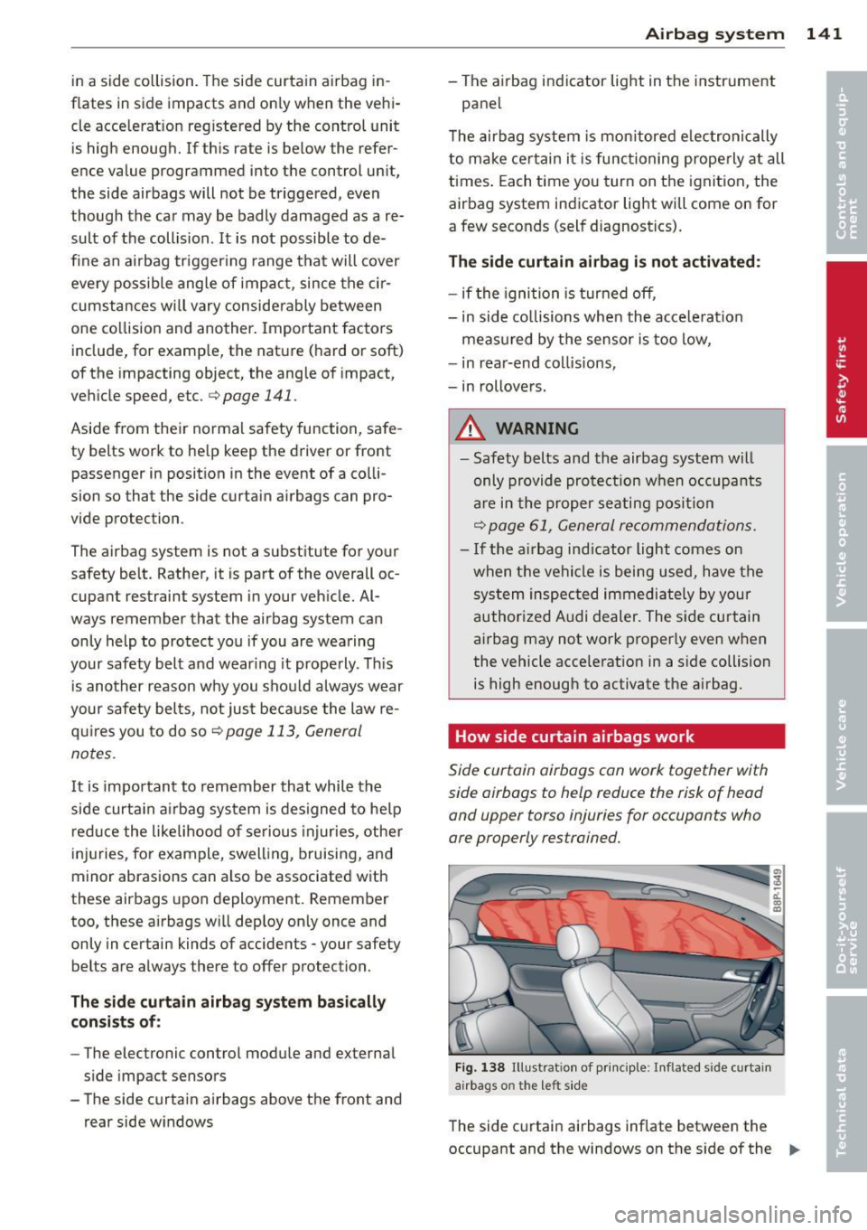
How side curtain airbags work
Side curtain airbags ca n work together with
side airbags to help reduce the risk of head
and upper torso injuries for occupants who
are properly restrained.
Fi g. 13 8 Illust rat io n o f pri nc iple: I nflated s ide c urtai n
a irbags o n the le ft sid e
The side c urtai n airbags inflate betwee n the
occupant and the windows on the s ide of the ..,.
Page 146 of 280
144 Child Safety
-Always install rear-facing child safety
seats on the rear seat.
- If you must install a rearward facing
child safety seat on the front passenger
seat in exceptional circumstances and
the
PASSENGER AIR BAG OFF light does
not come on and stay on, immediately
install the rear-facing child safety seat in
a rear seating position and have the air
bag system inspected immediately by
your authorized Audi dealer.
_& WARNING
If, in exceptional circumstances, you must
install a forward-facing child restraint on
the front passenger's seat:
- Always make sure the forward-facing
seat has been designed and certified by
its manufacturer for use on a front seat
with a passenger front and side airbag.
- Always follow the manufacturer's in
structions provided with the child safety
seat or carrier.
- Always move the passenger seat into its
rearmost position in the seat's fore and
aft adjustment range, as far away from
the airbag as possible before installing
the child restraint. The backrest must be adjusted to an upright position .
- Always make sure that the
PASSENGER
AIR BAG OFF
light comes on and stays
on all the time whenever the ignition is
switched on.
(D Tips
Always replace child restraints that were
installed in a vehicle during a crash. Dam
age to a child restraint that is not visible
could cause it to fail in another collision
situation.
Advanced front airbag system and children
Your vehicle is equipped with an "Advanced
Airbag System" in compliance with United
States Federal Motor Vehicle Safety Standard (FMVSS) 208 as applicable at the time your
vehicle was manufactured.
The Advanced Airbag system in your vehicle
has been certified to meet the "low-risk" re
quirements for 3- and 6-year old children on
the passenger side and small adults on the driver side. The low risk deployment criteria
are intended to reduce the risk of injury
through interaction with the airbag that can
occur, for example, by being too close to the
steering wheel and instrument panel when
the airbag inflates . In addition, the system
has been certified to comply with the "sup
pression" requirements of the Safety Stand
ard, to turn off the front airbag for infants up
to 12 months who are restrained on the front
passenger seat in child restraints that are list
ed in the Standard.
Even though your vehicle is equipped with an
Advanced Airbag system , all children, espe
cially those 12 years and younger, should al
ways ride in the back seat properly restrained
for their age and size. The airbag on the pas
senger side makes the front seat a potentially dangerous place for a child to ride . The front
seat is not the safest place for a child in a for
ward-facing child safety seat. It can be a very
dangerous place for an infant or a larger child
in a rearward-facing seat .
Advanced Airbags and the weight
sensing mat in the front seat
The Advanced Airbag System in your vehicle
detects the presence of an infant or child in a
child restraint on the front passenger seat us
ing the weight-sensing mat in the seat cush
ion and the sensor below the safety belt latch
on the front passenger seat that measures the
tension on the safety belt.
The weight -sensing mat measures total
weight of the child and the child safety seat
and a child blanket on the front passenger
seat. The weight on the front passenger seat
is related to the design of the child restraint
and its "footprint", the size and shape of the
bottom of the child restraint as it sits on the .,..
Page 147 of 280
seat. The weight of a child restraint and its
"footprint" vary for different kinds of child re
straints and for the different models of the
same kind of child restraint offered by child restra int manufacturers.
The weight ranges for the individual types, makes and mode ls of ch ild restra ints that the
NHTSA has specified in the Safety Standard
together with the we ight ranges of typical in
fants and typical 1 year -old child have been
stored in the control unit of the Advanced A ir
bag System . When a chi ld restraint is being
used on the front passenge r seat with a typi
cal 1 year -old ch ild, the A dvanced Airbag Sys
tem compares the we ight measured by the
weight sensing mat with the information stor
ed in the electronic control unit.
The electron ic contro l unit al so registers the
tension on the front passenger safety be lt.
The tension on the safety be lt for the front
passenger seat will be different for an adult
who is properly using the safety belt as com
pared to the tension on the be lt when it is
used to attach a child restraint to the seat.
T he sensor below the latch for the safety belt
for the front seat passenger measures the
tension on the belt . T he input from this sen
sor is t hen used w ith the we ight to "decide",
whether there is a ch ild restraint with a typ ica l
1 year-o ld child on the front passenger seat
and whether or not the airbag must be turned
off .
Child restraints and Advanced Airbags
Regard less of the child restraint that you use,
make sure that it has been certified to meet
United States Federal Motor Vehicle Safety
Standards and has been certified by its manu
facturer for use with an airbag . Always be sure
that the chi ld restraint is p roperly instal led at
one of the rear seat ing pos itions . If in excep
tional ci rcumstances you must use it on the
front passenger seat, carefu lly read all of the
information on child safety and Advanced Air
bags and heed a ll of the app licable WARN
INGS. Make certain that the child restraint is
correctly recognized by the weight-sensing
Child Sa fet y 145
mat inside the front passenger seat, that the
front passenger airbag is turned off and that
the a irbag status is always correct ly signaled
by the
PAS SENGE R AIR BAG OFF light.
Many types and models of child restraints
have been available over t he years, new mod
els are introduced regu larly incorporating new
and improved des igns and o lder models are
taken out of product ion. Ch ild restraints are
not standard ized . Child restraints of the same
type typ ically have d ifferent weights and sizes
and different 'footpr ints,' the size and shape
of the bottom of the ch ild restrai nt that sits
o n the seat, when they a re insta lled on a veh i
cle seat. These diffe rences make it v irtually
impossible to certify compliance with the re
quirements for advanced airbags with each
and every ch ild restraint that has ever been
sold in the past or will be sold over the course
of the useful life of your veh icle.
For this reason, the United States National
Highway Traffic Safety Adm inistrat ion has
published a list of spec ific type, makes and
models of child restraints that must be used
to certify comp liance of the Advanced Airbag
System in your veh icle with the suppression
requirements of Federal Motor Vehicle Safety
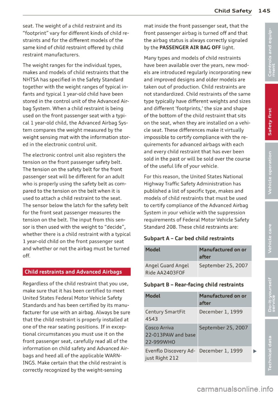
Standa rd 208. These chi ld restraints are :
Subpart A - Car bed child restraints
Model
Angel Guard Angel Ride AA 2403FOF
Manufactured on or
after
September 25, 2007
Subpart B - Rear-facing child restraints
Model Manufactured on or
after
Century SmartF it December 1, 1999
4543
Cosco Arriva September 25, 2007
22-013PAW and base
22-999WHO
Evenf lo Discovery Ad- December 1, 1999
just Right 212
I
j
•
•
....
Page 169 of 280

Energy management
Starting ability is optimized
Energy management controls the distribution
of electrical energy and thus optimizes the
availability of electrical energy for starting the engine .
If a vehicle with a conventional energy system
is not driven for a long period of time , the bat
tery is discharged by idling current consumers
(e.g. immobilizer). In ce rtain c ircumstances it
can result in there being insuff icient ene rgy
avai lab le to start the engine .
Intell igent energy management in your vehi
cle hand les the d istribution of electrical ener
gy. Starting ab il ity is markedly improved and
the life of the battery is extended.
Basically, energy management consists of
batt ery di agno sis, idlin g current man ag e
m ent
and dyn ami c en ergy m anage ment .
Batter y diagnosis
Battery diagnosis continuously determines
the state of the battery . Sensors determ ine
battery vo ltage, battery current and battery
temperature. This dete rm ines the current
state of charge and the powe r of the battery.
Idling curr ent man agement
Idling current management reduces ene rgy
consumption while the vehicle is stand ing .
W ith the ignition switched off, it cont ro ls the
energy supply to the va rious electr ical compo
nents . Data from battery diagnosis is consid
ered.
Depending on the battery's state of charge,
i nd ividua l consumers are gradual ly t urned off
to prevent excess ive d ischarge of the bat tery
and thus maintain starting capability .
Dynamic en ergy management
While the vehicle is being driven, dynamic en
e rgy management dist ributes the energy gen
e rated according to the needs of the individu
a l components.
It reg ulates cons umption, so
that more electrical energy is not being used
Int ellig ent technolog y 167
than is being generated and ensures an opti
mal state of charge for the battery.
(0 Tips
- But even energy management canno t
negate the limits of physics . Consider
that the power and life of a battery are
limited .
- If starting ability is threatened, you are
informed by a warning
r:!) page 168,
Driver notification in the instrument
cluster display.
What you should know
The highest priority is given to maintaining
starting capability.
The battery is severe ly taxed in short -distance
driving, in city traffic and during the cold time
of year. Abundant electrical energy is re quired, but only a little is generated .
It is also
critical if the engine is not running and electri
cal components are turned on . In this in
stance energy is be ing consumed but none is
being generated.
It is in precisely these situations that you will
notice energy management actively regulat
ing the d istribution of energy .
Vehicle stands for an e xtended peri od
If you do not drive your vehicle over a period
of several days or weeks, e lectr ical compo
nents are gradually cut back or switched off.
This reduces energy consumption and ma in
ta ins start ing capability over a longer period .
Take into considerat ion that when you unlock
your vehicle, some convenience functions, such as the remote key or power seat adjust
ment, may not be available . The conven ience
funct ions w ill be available again when you
tu rn on the ignition and start the engine .
With the engine turned off
If you listen to the radio, for example, w ith
the engine turned off, the battery is being d is-
charged.
~
•
•
Page 206 of 280
204 Checking and filling
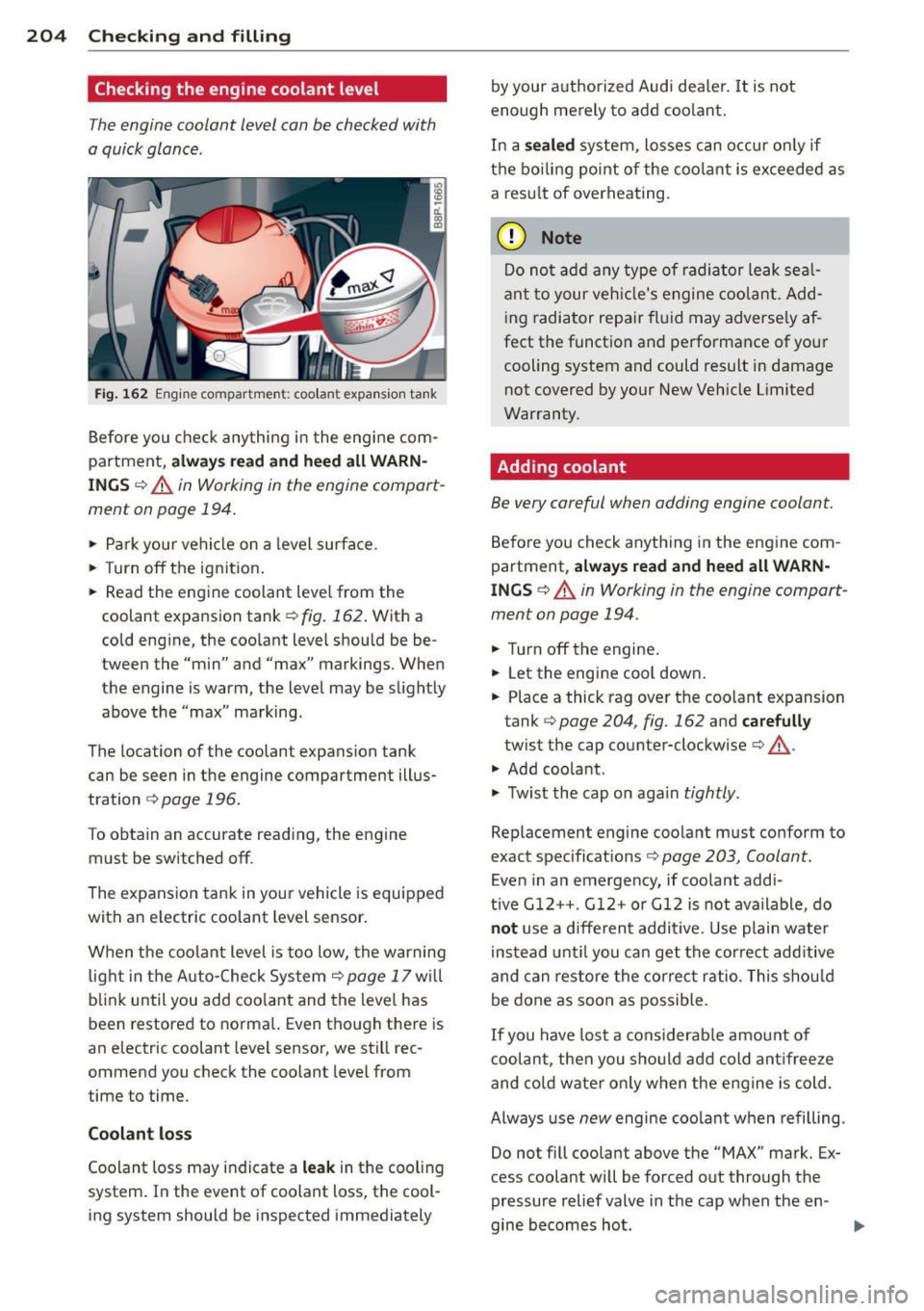
Checking the engine coolant level
The engine coolant level can be checked with
a quick glance .
Fig. 162 Engine compartme nt: coo lant expansio n tank
Before you check anything i n the eng ine com
partment,
a lw ays rea d and h eed all WARN
ING S ¢&. in Working in the engine compart
ment on page 194.
.. Park your vehicle on a level surface.
.. Turn
off the ignit ion .
.. Read the eng ine coolant leve l from the
coolant expansion tank<=>
fig. 162 . With a
cold eng ine, the coo lant level should be be
tween the "min" and "max" markings . When
the engine is warm, the level may be slightly above the "max" marking.
The location of the coolant expansion tank
can be seen in the engine compartment illus
tration
i:> page 196.
To obtain an accurate read ing, the engine
must be switched
off.
The expansion tank in yo ur vehicle is equipped
with an e lectric coolant level sensor .
When the coolant level is too low, the warning light in the Auto -Check System
c> page 17 w ill
blink until you add coo lant and the level has
been restored to norma l. Even though there is
an electric coolant level sensor, we still rec
ommend you check the coolant level from
time to time.
Coolant lo ss
Coolant loss may indicate a le ak in the cooling
system . In the event of coolant loss, the cool
ing system should be inspected immediately by your authorized Audi dea
ler .
It is not
enough merely to add coolant .
In a
se aled system, losses can occur on ly if
the boiling point of the coo lant is exceeded as
a res ult of overheating.
(D Note
Do not ad d any type of radiator leak sea l
ant to your veh icle's engine coolant . Add
i ng radiator repair fl uid may adverse ly af
fect the funct ion and performance of your
cooling system and could result in damage not covered by your New Veh icle Limited
Warranty .
Adding coolant
Be very careful when adding engine coolant.
Before you check anything in the eng ine com
partment,
a lw ays re a d and heed all WARN
INGS c::> A in Working in the engine compart
ment on page 194 .
.. Turn off the engine .
.. Let the engine cool down.
.. Place a thick rag over the coolant expansion
tank
c::> page 204, fig . 162 and ca refull y
twist the cap counter-clockwise c::> A.
.. Add coo lant .
.. Twist the cap on aga in
tightly .
Replacement engine coolant must conform to
exact spec ificat ions
c::> page 203, Coolant.
Even in an emergency, if coolant addi-
t ive G12++ . G 12+ or G12 is not ava ilable, do
n ot use a d iffe rent addit ive. Use plain water
instead unt il you can get the correct add itive
and can restore the correct ratio. This shou ld
be done as soon as possible .
If you have lost a considerab le amou nt of
c oolant, then you sho uld add cold ant ifree ze
and co ld wate r on ly when the engine is cold.
Always use
new engine coo lant when refilling .
Do not f ill coolant above the
"MAX" mark. Ex
cess coolant will be forced out through the
pressure relief valve in the cap when the en -
gine becomes hot .
Iii>
Page 233 of 280

remain continuously illuminated. This se
quence will continue upon subsequent vehicle
start-ups as long as the malfunction exists.
When the malfunction indicator is illuminat
ed, the system may not be able to detect or
signal low tire pressure as intended . TPMS
malfunct ions may occur for a variety of rea
sons, including the installation of replace
ment or alternate tires or wheels on the vehi
cle that prevent the TPMS from functioning
properly . Always check the TPMS malfunction
tellta le after replacing one or more tires or
wheels on your vehicle to ensure that the re
placement or alternate tires and wheels allow
the TPMS to continue to function properly.
Tire pressure indicator appears
Appl ies to vehicles: with tire pressur e monitoring sys te m
The tire pressure indicator in the instrument
cluster informs you if the tire pressure is too
low or if there is a system malfunction.
Fig. 172 Display : underinflation warning
Fig. 173 Display: System malfunction
Using the ABS sensors, the tire pressure moni
toring system compares the tire tread circum
ference and vibration characteristics of the in
dividual tires. If the pressure decreases in one
or more tires, this is indicated in the instru
ment cluster with a warning symbol
ti] and a
Tires and wheels 231
message r=!) fig. 172. The driver message in the
display goes out after 5 seconds. The driver
message can be displayed again by pressing
the
ICHECKI button @¢ page 10, fig . 3 . If on
ly one tire is affected, the display will indicate
its position .
The tire pressure monitoring must be reset in
the menu display each time the pressures are
adjusted (e .g. when switching between parti
al and full load pressure) or after changing or
replacing a tire on your vehicle¢
page 232.
You can find the recommended tire pressures
for your vehicle on the label on the driver's
door pillar¢
page 216.
Tire tread circumference and vibration charac
teristics can change and cause a tire pressure
warning if:
- the tire pressure in one or more tires is too
low,
- the tire has structural damage,
- the tire pressure was changed, wheels rotat- ed or replaced but the TPMS was not reset
¢page 232.
Warning symbols
ti] Loss of pressure in at least one tire¢&.
Check the tire or tires and replace or repair if
necessary. The indicator light
ti] in the instru
ment cluster also illuminates
¢page 13.
Check/correct the pressures of all four tires
and reset TPMS in the menu display .
11@1&1 (Tire Pressure Monitoring System) Tire
pressure! System malfunction . Ifll@IS, ap
pears after switching the ignition on or while
driving ¢
fig. 173 and the indicator light ti] in
the instrument cluster blinks for approx i
mately one minute and then stays on, there is
a system malfunction. See your autho rized
Audi dealer as soon as possible.
A WARNING
-If the tire pressure indicator appears in
the instrument cluster display, one or
more of your tires is significantly under
inflated. Reduce your speed immediately
and avoid any hard steering or braking ..,.
Page 246 of 280
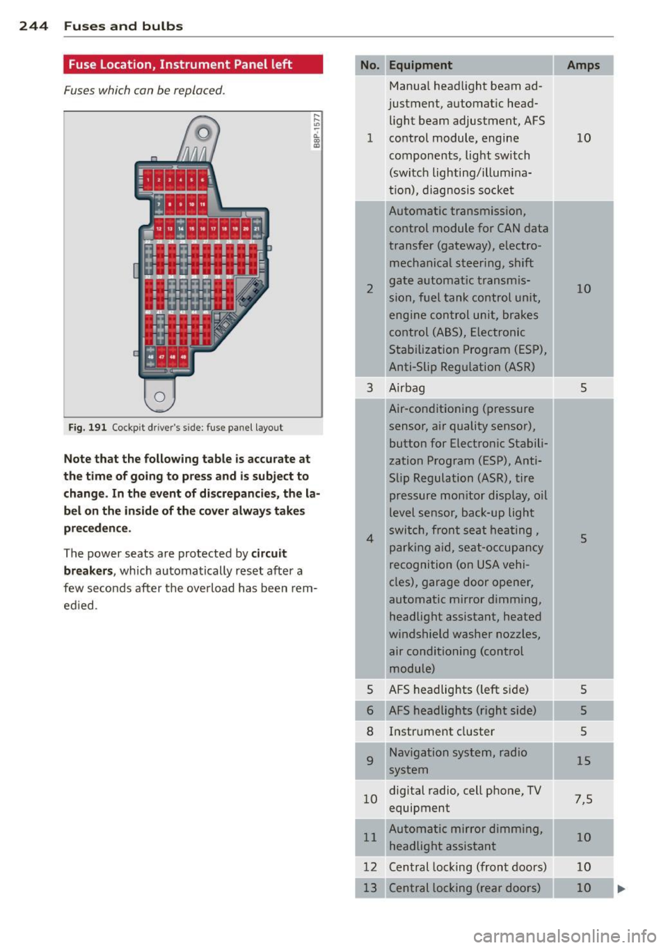
244 Fuses and bulbs
Fuse Location, Instrument Panel left
Fuses which can be replaced.
Fig. 191 Cockp it driver 's s ide: fuse pane l layout
Note that the following table is accurate at
the time of going to pr ess and i s subject to
change . In the event of d iscrepancies, the la
bel on the in side of the cover always take s
pr eceden ce .
The power seats are protected by circuit
break ers,
which automatically reset after a
few seconds after the ove rload has been rem
ed ied .
Equipment
Manua l head light beam ad
justment, a utomat ic head
light beam adjustment, AFS
1 co ntrol m odule, engine
components, light switch
(switch lighting/illumina
ti on), diagnosis socke t
2
3
4
5
6
8
9
Automatic transmission,
control module for CAN data
transfer (gateway), electro
mechanical steering, shift
gate automatic transmis
sion, fuel tank control unit,
engine control unit, brakes
control (A BS), Electronic
Stabili zation Program (ESP) ,
Anti-Slip Regulation (ASR)
Air bag
Air-conditioning (pressure
sensor, air quality sensor), button for Electronic Stabili
zation Program (ESP), Anti
Slip Regulat ion
(ASR), tire
pressure monitor display, oil
level senso r, back-up ligh t
s w itch, front se at he ati ng ,
p ark ing aid, sea t-occupancy
recognition (on USA vehi
cles), garage door opener,
automa tic mirror dimming,
headlight assistant, heated
windshield washer nozzles, air conditioning (control
module)
AFS headlights ( left si de)
AFS headlights (right side) Instr ument cluster
Navigation system, radio
system
1 0 digital
radio, cell phone, TV
equipment
11 Automatic mirror dimming,
headlight assistant
12 Central lock ing (front doors)
Central locking ( rear doors)
Amps
10
10
5
5
5
5
5
15
7 ,5
10
10
10
Page 247 of 280
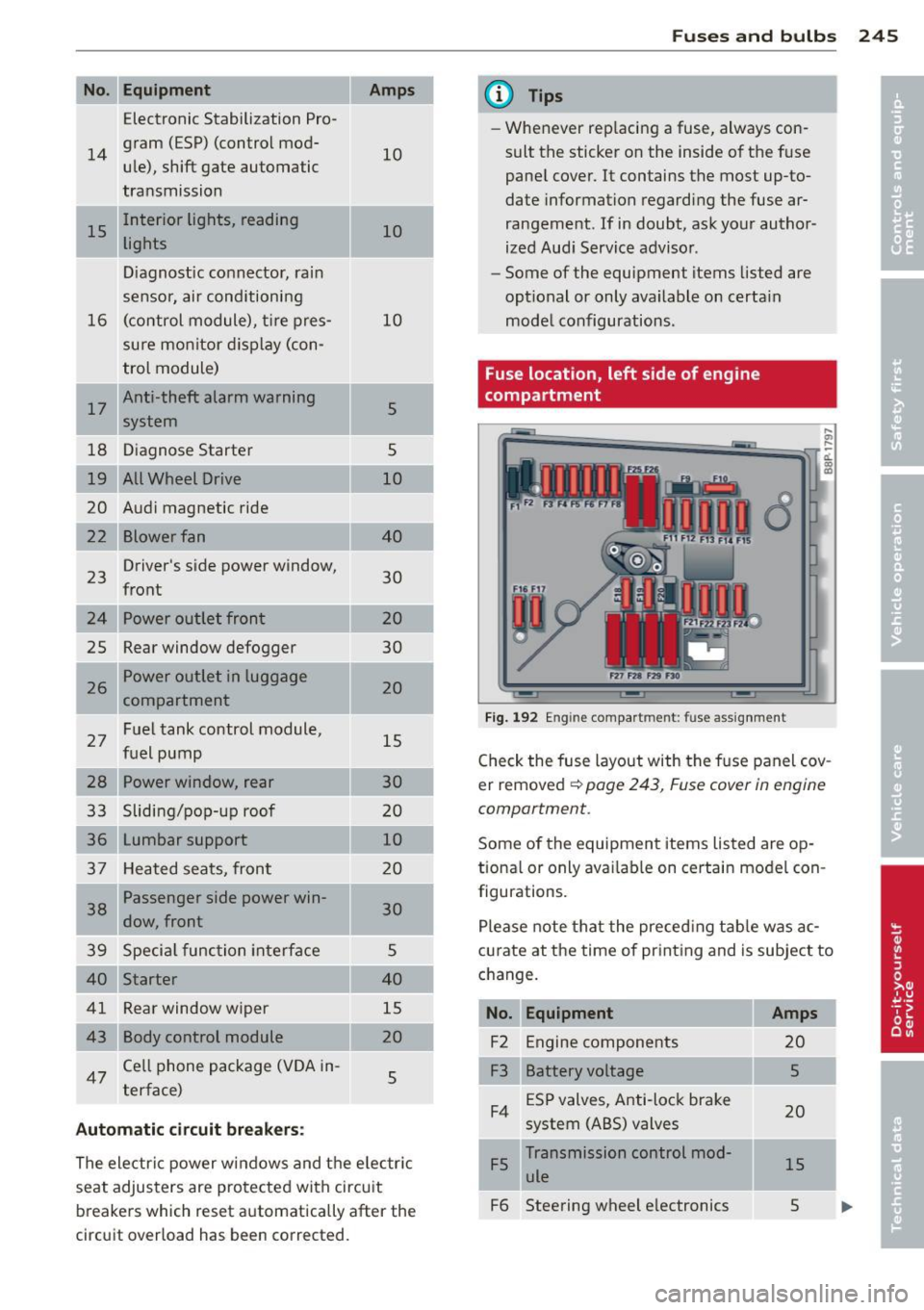
No. Equ ipment
Electronic Stabilization Pro-
14
gram (ESP) (control mod-
u le), shift gate automatic
transmission
15 Interior lights, reading
lights
Diagnostic connector, rain
sensor, air conditioning
16 (control module), t
ire pres-
sure monitor d isplay (con-
trol module)
I 17
Anti-theft alarm warning
system
18 D iagnose Starter
19 All Wheel D rive
20 Audi magnetic ride
Blower fan
23
Driver's
side power window,
front
24 Power outlet front
2S Rear window defogger
26 Power outlet in luggage
compartment
27 Fuel tank control module,
fuel pump
28 Power window, rear
33 Slidi ng/pop-up roof
36 Lumbar support
37 Heated sea ts, front
1 38
Passenger side power win-
dow, front
39 Specia l func tion interface
40 Starter
41 Rear window wiper
43 Body control module
47
Ce ll phone package (V OA in-
terface)
Automatic circuit breakers:
10
10
10
5
5
10
40
30
20
30
20
15
30
20 10
20
30
5
40
15
20 5
The electri c power w in dows and the e lectr ic
seat adjusters are pro tected with circu it
breake rs which reset automatically after the
circuit overload has been corrected.
Fu se s and bulb s 245
@ Tips
-Whenever rep lacing a fuse, always con
sult the sticker on the inside of the f use
pane l cover. It contains the most up-to
date information regarding the fuse ar
rangement. If in doubt, ask your author
ized Aud i Service adviso r.
- Some of the equipment items listed are
opt ional or only available on certa in
mode l configurations.
Fuse location, left side of engine
compartment
Fig . 192 En gine compar tment : fuse assig nment
,._
-d. a, a>
Check the fuse layout with the f use panel cov
er removed
¢ page 243, Fuse cover in engine
comportment.
Some of the equipmen t items listed are op
tiona l or only ava ilab le on certain model con
figurations.
Please note tha t the preced ing tab le was ac
c u rate at the time of pr int ing and is subject to
c h ange.
No. Equipment
F2 Engine compone nts
F3 Battery voltage ESP valves, Anti-lock brake
F4 system (ABS) valves
Transmission control mod
F5 ule
F6 Steering wheel e lectronics
Amps
20
5
20
15
s
Page 248 of 280

246 Fuses and bulbs
I
I
I
No. Equipment
FlO Engine control module,
main relay
Control module for CAN da
F12 ta transfer (gateway)
F13 Engine control module (die
sel engine/gasoline engine)
Fl 4 Engine components (diesel
engine), ignition coils
FlS
F16
F17
F18 Preheating control module/
engine component, tank di
agnosis, oxygen sensor
Body control module (right)
Horn
Audio amplifier
Flg Front windshield wiper sys
tem
F 2 0
Water pump/volume regula
tor valve
F22
F23
F24
F25
F26 Oxygen sensor (diesel en
gine/gasoline engine)/vac
uum pump
C
lutch pedal switch, brake
light switch
Engine relay, water pump/
engine components/volume regulator valve
Eng ine components, water
pump
Pump (ESP/ABS), ABS valve
Body control module (left)
-Amps
5/10
5
15,20,
25/30
20
5/10 30 15
--30
30
10/15, 20
10/15 /20
5
5/10
/15
10
40
-·-- --·-
30
40
F27 Secondary
air pump, pre-
heating control module
__ , ..
F29 Fuse assignment in the left
side instrument pane l (spe-
cia l equipment)
Power supply relay terminal
15 so
so
Bulbs
Replacing light bulbs
For your safety, we recommend that you have
your authorized Audi dealer replace burned
out bulbs for you.
It is becoming increasingly more and more
difficult to replace vehicle light bulbs since in
many cases, other parts of the car must first
be removed before you are able to get to the
bulb. This applies especially to the light bulbs
in the front of your ca r which you can only
reach through the engine compartment.
Sheet metal and bulb holders can have sharp
edges that can cause serious cuts, and parts
must be cor rectly taken apart and then prop
erly put back together to help prevent break
age of parts and long term damage from wa
ter that can enter housings that have not been
properly re sea led.
For your safety, we recommend that you have
your authorized Audi dea ler replace any bulbs
for you, since your dealer has the proper tools,
the correct bulbs and the expertise.
Gas discharge lamp s (Xenon lights)*:
Due to the high e lectr ica l voltage, have the
bulbs replaced by a qualified techn ic ian.
Head lights with Xenon light can be identified
by the high voltage sticker.
_& WARNING ~
Contact with high-vo ltage components of
the electrical system and improper re
placement of gas discharge (Xenon) head
light bulbs can cause serious personal in
jury and death.
- Xenon bulbs are pressur ized and can ex
plode when being changed.
- Changing Xenon lamps requires the spe
cial tra ining, instructions and equip
ment.
- On ly an authorized Audi dealer or other
qualified workshop should change the bulbs in gas discharge lamps .
Page 266 of 280
264 Index .:..:..:..::....::..
...:..._ ___________________________ _
A
ABS
refer to Anti-lock brake system . ... .. . 164
Accessories .. ... .. ..... ... .. .. .. .. . 26 1
Acoust ic park assist ........ .. .. .... .. 93
AC (a ir cond itioner) ......... .. .. .. .. .. 81
Adapter for anti-theft wheel bolts . .. .. . 238
Adaptive light
defective . . . . . . . . . . . . . . . . . . . . . . . . . . 21
Adding Engine coolant .......... .... ..... . 204
Engine oil . ...... ....... ... .. .... . 200
Windshield washer fluid ............ 211
Addit ional accessories .......... .... . 261
Additional heater Climate controls . . . . . . . . . . . . . . . . . . . . 85
Additives Engine oil . ............... ... .. .. . 200
Adj ustab le steering wheel column .... .. 88
Adjusting Steer ing wheel column ........ .. .... 88
Adjusting front seats ........ ... .... .. 61
Advanced Airbag System
Components ... .......... .. .. .. .. . 129
Fr ont airbags ................ .... . 127
How the components work together .. 130
Monitoring ................. ..... . 133
PASS ENG ER A IR BAG OFF light .. .... . 133
A irbag
Warning/indicator lights ............. 16
A irbag system . . . . . . . . . . . . . . . . . 122, 139
Advanced Airbag System . . . . . . . . . . . . 126
Care . .. .. ............... .. .. .... . 135
Ch ildren . .... ........... .. .. .. .. . 144
Ch ild r estra ints ........... .. .. .. .. . 145
Components (front airbags) . ... .... . 129
Danger of fitting a child safety seat on
the front passenger seat . . . . . . . . . . . . 123
Disposal . ................. .. .... . 135
Front airbags . ........... .. .. .... . 126
How do the front airbags work? . . . . . . 131
H ow many airbags does my vehicle
have? ..... .......... ...... ... .. . 129
I mportant things to know .... .. .... . 122
I ndicator light ........... .. .. .. .. . 133
Monitoring ................. ..... . 133 Repairs ...
.... .. ............. .... 135
Side airbags ..... ................ . 137
S ide curtain airbags ................ 140
When must the system be inspected? 133
Airbag System
Weight-sensing mat .............. . 144
Air conditioner .. .. ................ .. 81
also refer to Climate controls .. .. .. .. . 79
Air conditioning Switching on and off ........... .. .. . 81
Air distribution Climate controls . ................. .. 83
Air outlets Adjusting the outlets for rapid defrost -
ing/defogging ... ................ .. 84
Climate controls . .............. ..... 84
Air quality sensor . . . . . . . . . . . . . . . . . . . . 82
Air recirculation . .. ... .......... .... . 83
Climate controls .. ............. .... . 82
When should I use the air recirculation? 82
Air recirculation mode Climate controls . ................. .. 82
All-wheel drive Winter tires ... .. ... .......... .... 227
Alloy wheels ...... ................ . 182
All Wheel Drive .... ............. .... 166
Alternator
refer to Generator ............. .. .. . 16
Aluminum alloy wheels .... ...... .... 182
Ambient lighting . . . . . . . . . . . . . . . . . . . . 52
Anti-lock brake system How the ABS system works ........ .. 164
Warning/ind icator lights ........ .. .. . 18
Anti -theft systems
Anti-Theft Alarm System . . . . . . . . . . . . . 42
Anti-theft wheel bolts ........... .... 238
Armrest Center armrest . . . . . . . . . . . . . . . . . . . . . 66
Rear armrest .... ................ .. 67
Asterisk What does it mean when something is
marked with an aster isk? ........ .... .. 6
Audi magnetic ride . . . . . . . . . . . . . . . 22, 9S
Description . . . . . . . . . . . . . . . . . . . . . . . . 95
Indicator light ... ....... ...... .. .. . 22
Audi Service Repair Manuals and Litera-
ture 259