tow AUDI S4 1997 B5 / 1.G 01E Transmission Bearing House And Torsen Differential Workshop Manual
[x] Cancel search | Manufacturer: AUDI, Model Year: 1997, Model line: S4, Model: AUDI S4 1997 B5 / 1.GPages: 38, PDF Size: 0.87 MB
Page 5 of 38
34-57
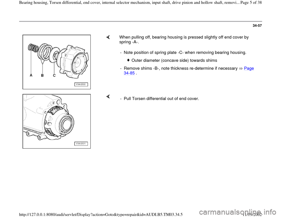
When pulling off, bearing housing is pressed slightly off end cover by
spring -A-.
- Note position of spring plate -C- when removing bearing housing.
Outer diameter (concave side) towards shims
- Remove shims -B-, note thickness re-determine if necessary Page
34
-85
.
- Pull Torsen differential out of end cover.
Pa
ge 5 of 38 Bearin
g housin
g, Torsen differential, end cover, internal selector mechanism, in
put shaft, drive
pinion and hollow shaft, removi...
11/19/2002 htt
p://127.0.0.1:8080/audi/servlet/Dis
play?action=Goto&t
yp
e=re
pair&id=AUDI.B5.TM03.34.5
Page 16 of 38
34-68
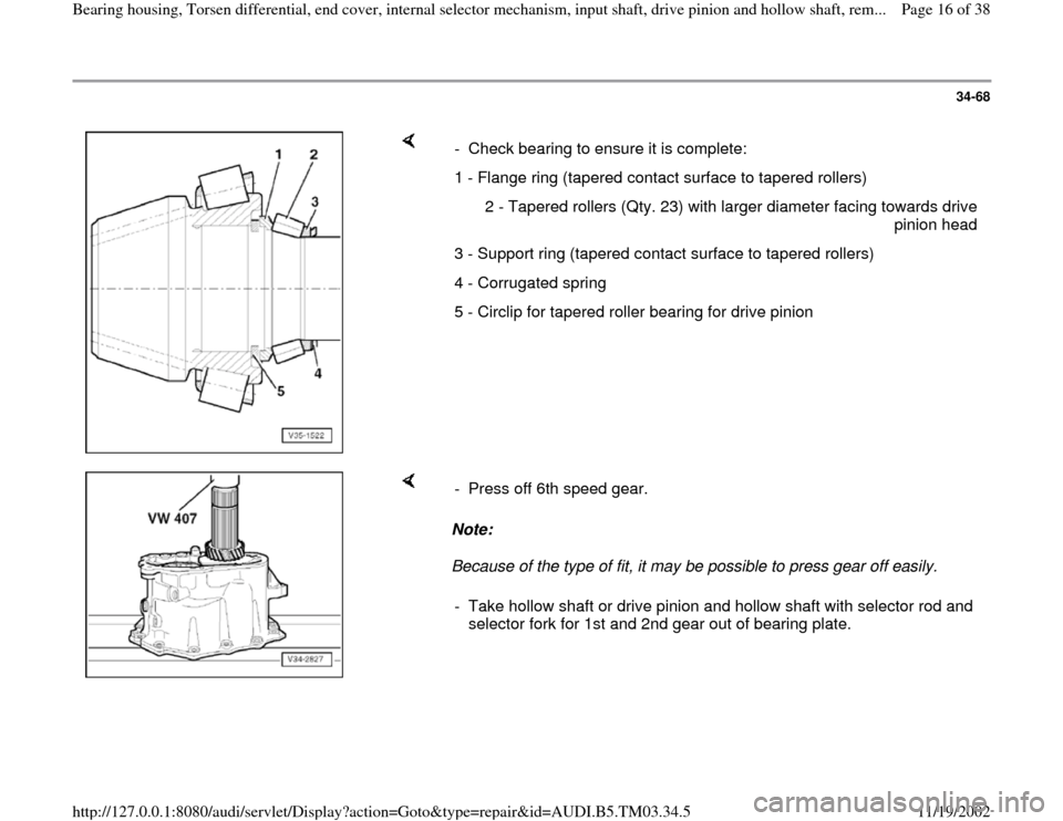
- Check bearing to ensure it is complete:
1 - Flange ring (tapered contact surface to tapered rollers)
2 - Tapered rollers (Qty. 23) with larger diameter facing towards drive
pinion head
3 - Support ring (tapered contact surface to tapered rollers)
4 - Corrugated spring
5 - Circlip for tapered roller bearing for drive pinion
Note:
Because of the type of fit, it may be possible to press gear off easily. - Press off 6th speed gear.
- Take hollow shaft or drive pinion and hollow shaft with selector rod and
selector fork for 1st and 2nd gear out of bearing plate.
Pa
ge 16 of 38 Bearin
g housin
g, Torsen differential, end cover, internal selector mechanism, in
put shaft, drive
pinion and hollow shaft, rem...
11/19/2002 htt
p://127.0.0.1:8080/audi/servlet/Dis
play?action=Goto&t
yp
e=re
pair&id=AUDI.B5.TM03.34.5
Page 17 of 38
34-69
Installing
- Fit hollow shaft with selector fork and selector
rod for 1st and 2nd gear (without follower) into
bearing plate.
-
Heat 6th gear to approx. 120 C and fit on. Installation position: shoulder towards tapered roller bearing
- Press onto stop; ensure there is no play.
- Grease drive pinion/hollow shaft tapered roller bearing with multi-
purpose grease before inserting.
Allocation Page 34
-68
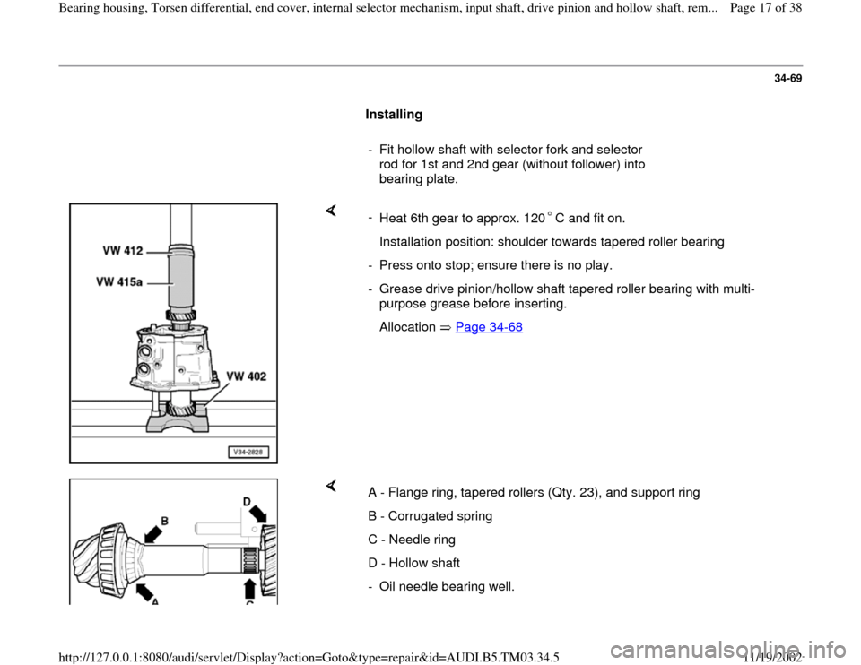
A - Flange ring, tapered rollers (Qty. 23), and support ring
B - Corrugated spring
C - Needle ring
D - Hollow shaft
- Oil needle bearing well.
Pa
ge 17 of 38 Bearin
g housin
g, Torsen differential, end cover, internal selector mechanism, in
put shaft, drive
pinion and hollow shaft, rem...
11/19/2002 htt
p://127.0.0.1:8080/audi/servlet/Dis
play?action=Goto&t
yp
e=re
pair&id=AUDI.B5.TM03.34.5
Page 19 of 38
34-70
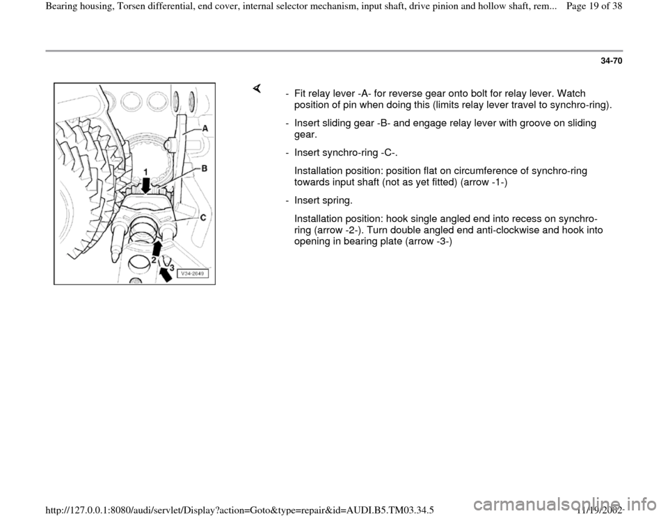
- Fit relay lever -A- for reverse gear onto bolt for relay lever. Watch
position of pin when doing this (limits relay lever travel to synchro-ring).
- Insert sliding gear -B- and engage relay lever with groove on sliding
gear.
- Insert synchro-ring -C-.
Installation position: position flat on circumference of synchro-ring
towards input shaft (not as yet fitted) (arrow -1-)
- Insert spring.
Installation position: hook single angled end into recess on synchro-
ring (arrow -2-). Turn double angled end anti-clockwise and hook into
opening in bearing plate (arrow -3-)
Pa
ge 19 of 38 Bearin
g housin
g, Torsen differential, end cover, internal selector mechanism, in
put shaft, drive
pinion and hollow shaft, rem...
11/19/2002 htt
p://127.0.0.1:8080/audi/servlet/Dis
play?action=Goto&t
yp
e=re
pair&id=AUDI.B5.TM03.34.5
Page 20 of 38
34-71
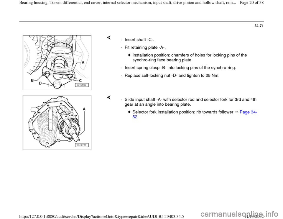
- Insert shaft -C-.
- Fit retaining plate -A-.
Installation position: chamfers of holes for locking pins of the
synchro-ring face bearing plate
- Insert spring clasp -B- into locking pins of the synchro-ring.
- Replace self-locking nut -D- and tighten to 25 Nm.
- Slide input shaft -A- with selector rod and selector fork for 3rd and 4th
gear at an angle into bearing plate.
Selector fork installation position: rib towards follower Page 34
-
52
Pa
ge 20 of 38 Bearin
g housin
g, Torsen differential, end cover, internal selector mechanism, in
put shaft, drive
pinion and hollow shaft, rem...
11/19/2002 htt
p://127.0.0.1:8080/audi/servlet/Dis
play?action=Goto&t
yp
e=re
pair&id=AUDI.B5.TM03.34.5
Page 24 of 38
34-75
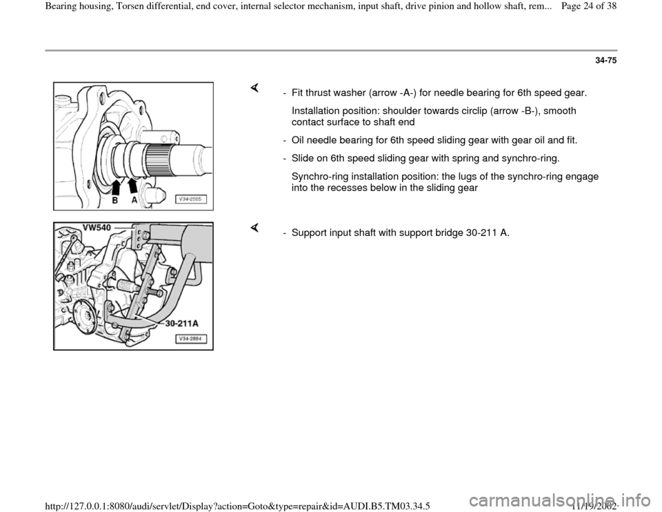
- Fit thrust washer (arrow -A-) for needle bearing for 6th speed gear.
Installation position: shoulder towards circlip (arrow -B-), smooth
contact surface to shaft end
- Oil needle bearing for 6th speed sliding gear with gear oil and fit.
- Slide on 6th speed sliding gear with spring and synchro-ring.
Synchro-ring installation position: the lugs of the synchro-ring engage
into the recesses below in the sliding gear
- Support input shaft with support bridge 30-211 A.
Pa
ge 24 of 38 Bearin
g housin
g, Torsen differential, end cover, internal selector mechanism, in
put shaft, drive
pinion and hollow shaft, rem...
11/19/2002 htt
p://127.0.0.1:8080/audi/servlet/Dis
play?action=Goto&t
yp
e=re
pair&id=AUDI.B5.TM03.34.5
Page 26 of 38
34-77
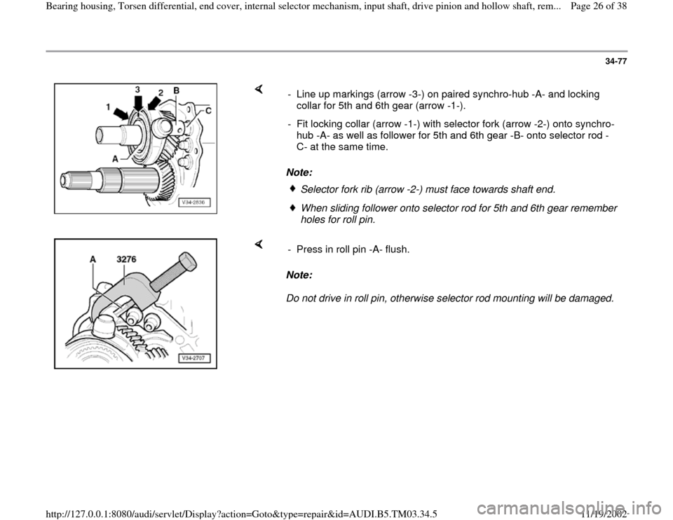
Note: - Line up markings (arrow -3-) on paired synchro-hub -A- and locking
collar for 5th and 6th gear (arrow -1-).
- Fit locking collar (arrow -1-) with selector fork (arrow -2-) onto synchro-
hub -A- as well as follower for 5th and 6th gear -B- onto selector rod -
C- at the same time.
Selector fork rib (arrow -2-) must face towards shaft end. When sliding follower onto selector rod for 5th and 6th gear remember
holes for roll pin.
Note:
Do not drive in roll pin, otherwise selector rod mounting will be damaged. - Press in roll pin -A- flush.
Pa
ge 26 of 38 Bearin
g housin
g, Torsen differential, end cover, internal selector mechanism, in
put shaft, drive
pinion and hollow shaft, rem...
11/19/2002 htt
p://127.0.0.1:8080/audi/servlet/Dis
play?action=Goto&t
yp
e=re
pair&id=AUDI.B5.TM03.34.5
Page 28 of 38
34-79
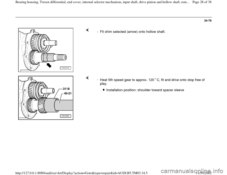
- Fit shim selected (arrow) onto hollow shaft.
-
Heat 5th speed gear to approx. 120 C, fit and drive onto stop free of
play.
Installation position: shoulder toward spacer sleeve
Pa
ge 28 of 38 Bearin
g housin
g, Torsen differential, end cover, internal selector mechanism, in
put shaft, drive
pinion and hollow shaft, rem...
11/19/2002 htt
p://127.0.0.1:8080/audi/servlet/Dis
play?action=Goto&t
yp
e=re
pair&id=AUDI.B5.TM03.34.5
Page 31 of 38
34-82
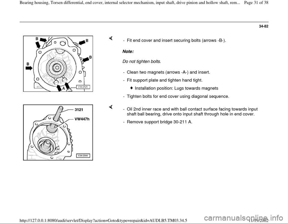
Note:
Do not tighten bolts. - Fit end cover and insert securing bolts (arrows -B-).
- Clean two magnets (arrows -A-) and insert.
- Fit support plate and tighten hand tight.
Installation position: Lugs towards magnets
- Tighten bolts for end cover using diagonal sequence.
- Oil 2nd inner race and with ball contact surface facing towards input
shaft ball bearing, drive onto input shaft through hole in end cover.
- Remove support bridge 30-211 A.
Pa
ge 31 of 38 Bearin
g housin
g, Torsen differential, end cover, internal selector mechanism, in
put shaft, drive
pinion and hollow shaft, rem...
11/19/2002 htt
p://127.0.0.1:8080/audi/servlet/Dis
play?action=Goto&t
yp
e=re
pair&id=AUDI.B5.TM03.34.5
Page 37 of 38
34-87
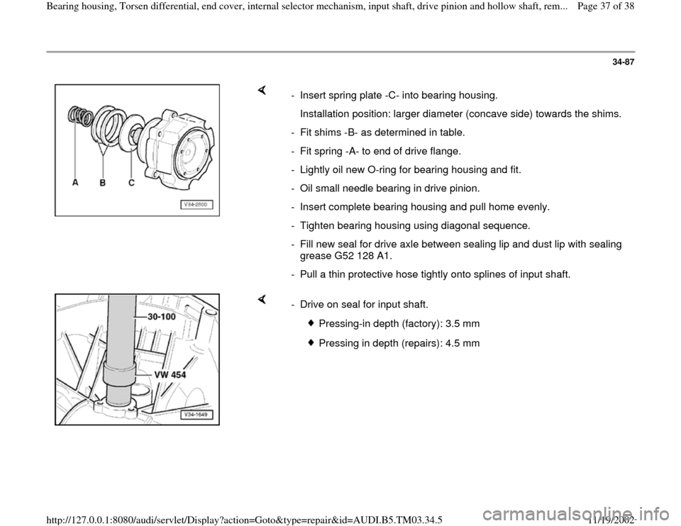
- Insert spring plate -C- into bearing housing.
Installation position: larger diameter (concave side) towards the shims.
- Fit shims -B- as determined in table.
- Fit spring -A- to end of drive flange.
- Lightly oil new O-ring for bearing housing and fit.
- Oil small needle bearing in drive pinion.
- Insert complete bearing housing and pull home evenly.
- Tighten bearing housing using diagonal sequence.
- Fill new seal for drive axle between sealing lip and dust lip with sealing
grease G52 128 A1.
- Pull a thin protective hose tightly onto splines of input shaft.
- Drive on seal for input shaft.
Pressing-in depth (factory): 3.5 mm
Pressing in depth (repairs): 4.5 mm
Pa
ge 37 of 38 Bearin
g housin
g, Torsen differential, end cover, internal selector mechanism, in
put shaft, drive
pinion and hollow shaft, rem...
11/19/2002 htt
p://127.0.0.1:8080/audi/servlet/Dis
play?action=Goto&t
yp
e=re
pair&id=AUDI.B5.TM03.34.5