Turbo AUDI S4 1998 B5 / 1.G Engine Manual
[x] Cancel search | Manufacturer: AUDI, Model Year: 1998, Model line: S4, Model: AUDI S4 1998 B5 / 1.GPages: 72, PDF Size: 3.25 MB
Page 46 of 72
47
SSP/198/13
Exhaust gas temperature sender
G235 and G236
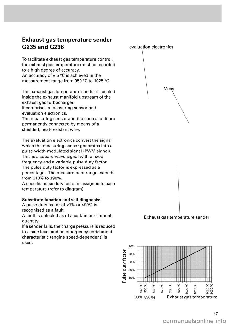
To facilitate exhaust gas temperature control,
the exhaust gas temperature must be recorded
to a high degree of accuracy.
An accuracy of ± 5 °C is achieved in the
measurement range from 950 °C to 1025 °C.
The exhaust gas temperature sender is located
inside the exhaust manifold upstream of the
exhaust gas turbocharger.
It comprises a measuring sensor and
evaluation electronics.
The measuring sensor and the control unit are
permanently connected by means of a
shielded, heat-resistant wire.
The evaluation electronics convert the signal
which the measuring sensor generates into a
pulse-width-modulated signal (PWM signal).
This is a square-wave signal with a fixed
frequency and a variable pulse duty factor.
The pulse duty factor is expressed as a
percentage . The measurement range extends
from
³
10% to
£
90%.
A specific pulse duty factor is assigned to each
temperature (refer to diagram).
Substitute function and self-diagnosis:
A pulse duty factor of <1% or >99% is
recognised as a fault.
A fault is detected as of a certain enrichment
quantity.
If a sender fails, the charge pressure is reduced
to a safe level and an emergency enrichment
characteristic (engine speed-dependent) is
used.
Exhaust gas temperature sender
evaluation electronics
SSP 198/56
90%
70%
50%
30%
10%
945°C
950°C
960°C
970°C
980°C
990°C
1000°C
1010°C
1025°C
1030°C
Exhaust gas temperature
Pulse duty factor
Meas.
Page 48 of 72
49
Sensors
Charge pressure sender G31
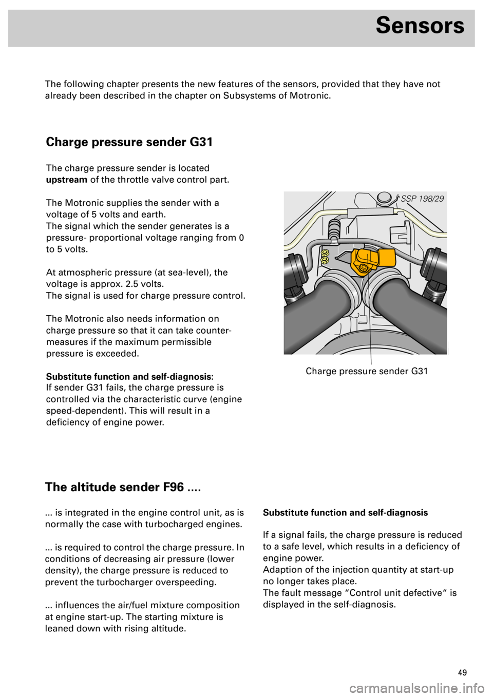
The charge pressure sender is located
upstream of the throttle valve control part.
The Motronic supplies the sender with a
voltage of 5 volts and earth.
The signal which the sender generates is a
pressure- proportional voltage ranging from 0
to 5 volts.
At atmospheric pressure (at sea-level), the
voltage is approx. 2.5 volts.
The signal is used for charge pressure control.
The Motronic also needs information on
charge pressure so that it can take counter-
measures if the maximum permissible
pressure is exceeded.
Substitute function and self-diagnosis:
If sender G31 fails, the charge pressure is
controlled via the characteristic curve (engine
speed-dependent). This will result in a
deficiency of engine power.
SSP 198/29
Charge pressure sender G31
The altitude sender F96 ....
... is integrated in the engine control unit, as is
normally the case with turbocharged engines.
... is required to control the charge pressure. In
conditions of decreasing air pressure (lower
density), the charge pressure is reduced to
prevent the turbocharger overspeeding.
... influences the air/fuel mixture composition
at engine start-up. The starting mixture is
leaned down with rising altitude.Substitute function and self-diagnosis
If a signal fails, the charge pressure is reduced
to a safe level, which results in a deficiency of
engine power.
Adaption of the injection quantity at start-up
no longer takes place.
The fault message “Control unit defective“ is
displayed in the self-diagnosis.
The following chapter presents the new features of the sensors, provided that they have not
already been described in the chapter on Subsystems of Motronic.
Page 51 of 72
52
Sensors
Lambda probes G39 and G108
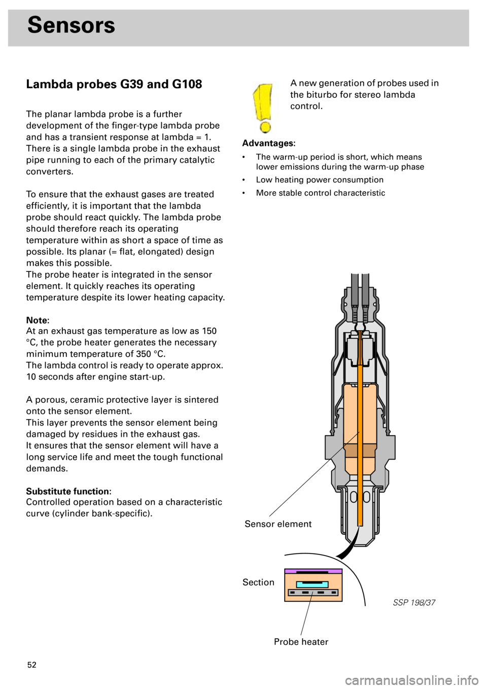
The planar lambda probe is a further
development of the finger-type lambda probe
and has a transient response at lambda = 1.
There is a single lambda probe in the exhaust
pipe running to each of the primary catalytic
converters.
To ensure that the exhaust gases are treated
efficiently, it is important that the lambda
probe should react quickly. The lambda probe
should therefore reach its operating
temperature within as short a space of time as
possible. Its planar (= flat, elongated) design
makes this possible.
The probe heater is integrated in the sensor
element. It quickly reaches its operating
temperature despite its lower heating capacity.
Note:
At an exhaust gas temperature as low as 150
°C, the probe heater generates the necessary
minimum temperature of 350 °C.
The lambda control is ready to operate approx.
10 seconds after engine start-up.
A porous, ceramic protective layer is sintered
onto the sensor element.
This layer prevents the sensor element being
damaged by residues in the exhaust gas.
It ensures that the sensor element will have a
long service life and meet the tough functional
demands.
Substitute function:
Controlled operation based on a characteristic
curve (cylinder bank-specific).A new generation of probes used in
the biturbo for stereo lambda
control.
Advantages:
• The warm-up period is short, which means
lower emissions during the warm-up phase
• Low heating power consumption
• More stable control characteristic
SSP 198/37
Section
Probe heater
Sensor element
Page 61 of 72
62
Functional diagram
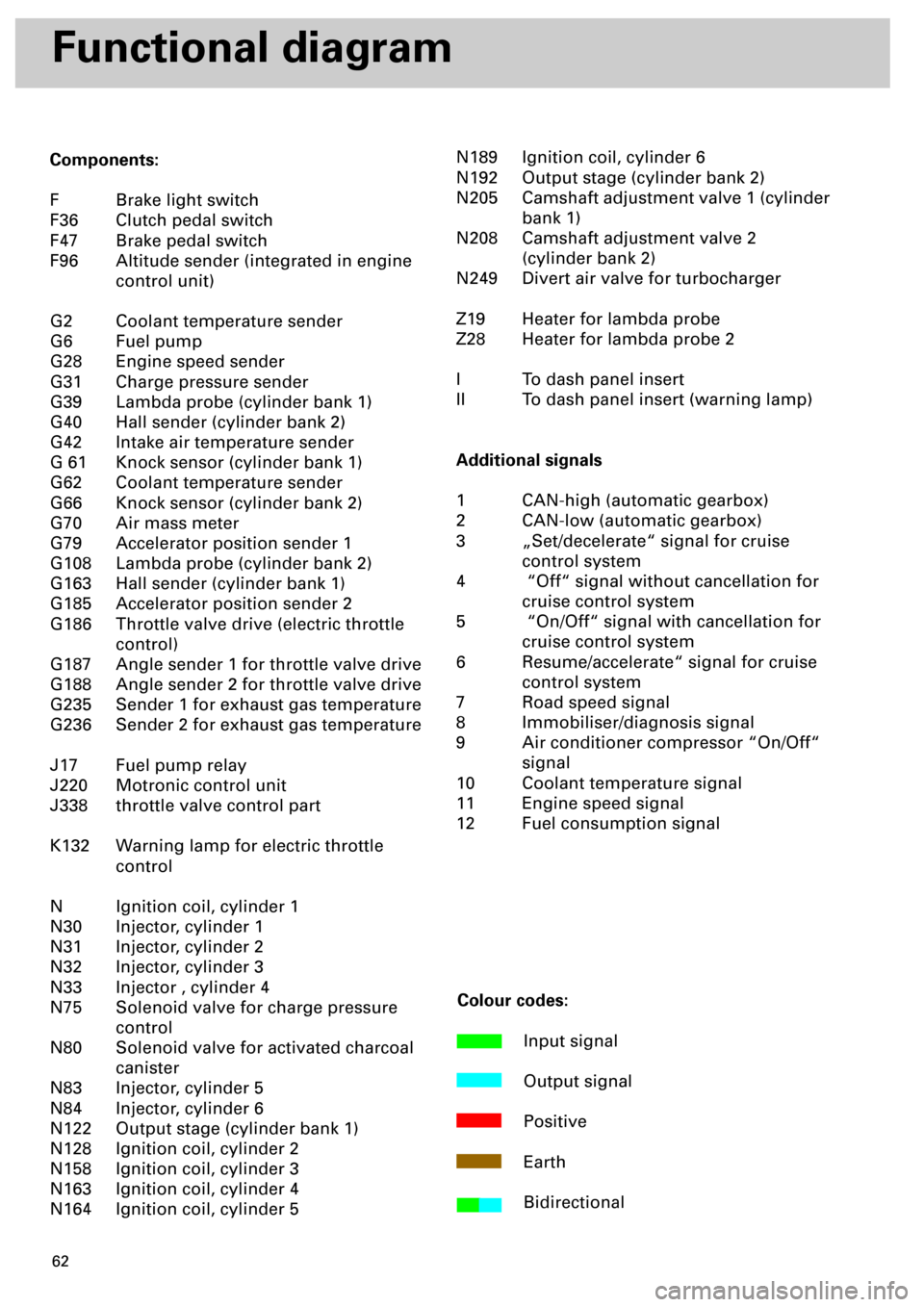
Components:
F Brake light switch
F36 Clutch pedal switch
F47 Brake pedal switch
F96 Altitude sender (integrated in engine
control unit)
G2 Coolant temperature sender
G6 Fuel pump
G28 Engine speed sender
G31 Charge pressure sender
G39 Lambda probe (cylinder bank 1)
G40 Hall sender (cylinder bank 2)
G42 Intake air temperature sender
G 61 Knock sensor (cylinder bank 1)
G62 Coolant temperature sender
G66 Knock sensor (cylinder bank 2)
G70 Air mass meter
G79 Accelerator position sender 1
G108 Lambda probe (cylinder bank 2)
G163 Hall sender (cylinder bank 1)
G185 Accelerator position sender 2
G186 Throttle valve drive (electric throttle
control)
G187 Angle sender 1 for throttle valve drive
G188 Angle sender 2 for throttle valve drive
G235 Sender 1 for exhaust gas temperature
G236 Sender 2 for exhaust gas temperature
J17 Fuel pump relay
J220 Motronic control unit
J338 throttle valve control part
K132 Warning lamp for electric throttle
control
N Ignition coil, cylinder 1
N30 Injector, cylinder 1
N31 Injector, cylinder 2
N32 Injector, cylinder 3
N33 Injector , cylinder 4
N75 Solenoid valve for charge pressure
control
N80 Solenoid valve for activated charcoal
canister
N83 Injector, cylinder 5
N84 Injector, cylinder 6
N122 Output stage (cylinder bank 1)
N128 Ignition coil, cylinder 2
N158 Ignition coil, cylinder 3
N163 Ignition coil, cylinder 4
N164 Ignition coil, cylinder 5N189 Ignition coil, cylinder 6
N192 Output stage (cylinder bank 2)
N205 Camshaft adjustment valve 1 (cylinder
bank 1)
N208 Camshaft adjustment valve 2
(cylinder bank 2)
N249 Divert air valve for turbocharger
Z19 Heater for lambda probe
Z28 Heater for lambda probe 2
I To dash panel insert
II To dash panel insert (warning lamp)
Additional signals
1 CAN-high (automatic gearbox)
2 CAN-low (automatic gearbox)
3 „Set/decelerate“ signal for cruise
control system
4 “Off“ signal without cancellation for
cruise control system
5 “On/Off“ signal with cancellation for
cruise control system
6 Resume/accelerate“ signal for cruise
control system
7 Road speed signal
8 Immobiliser/diagnosis signal
9 Air conditioner compressor “On/Off“
signal
10 Coolant temperature signal
11 Engine speed signal
12 Fuel consumption signal
Colour codes:
Input signal
Output signal
Positive
Earth
Bidirectional
Page 65 of 72
66
Power Transmission
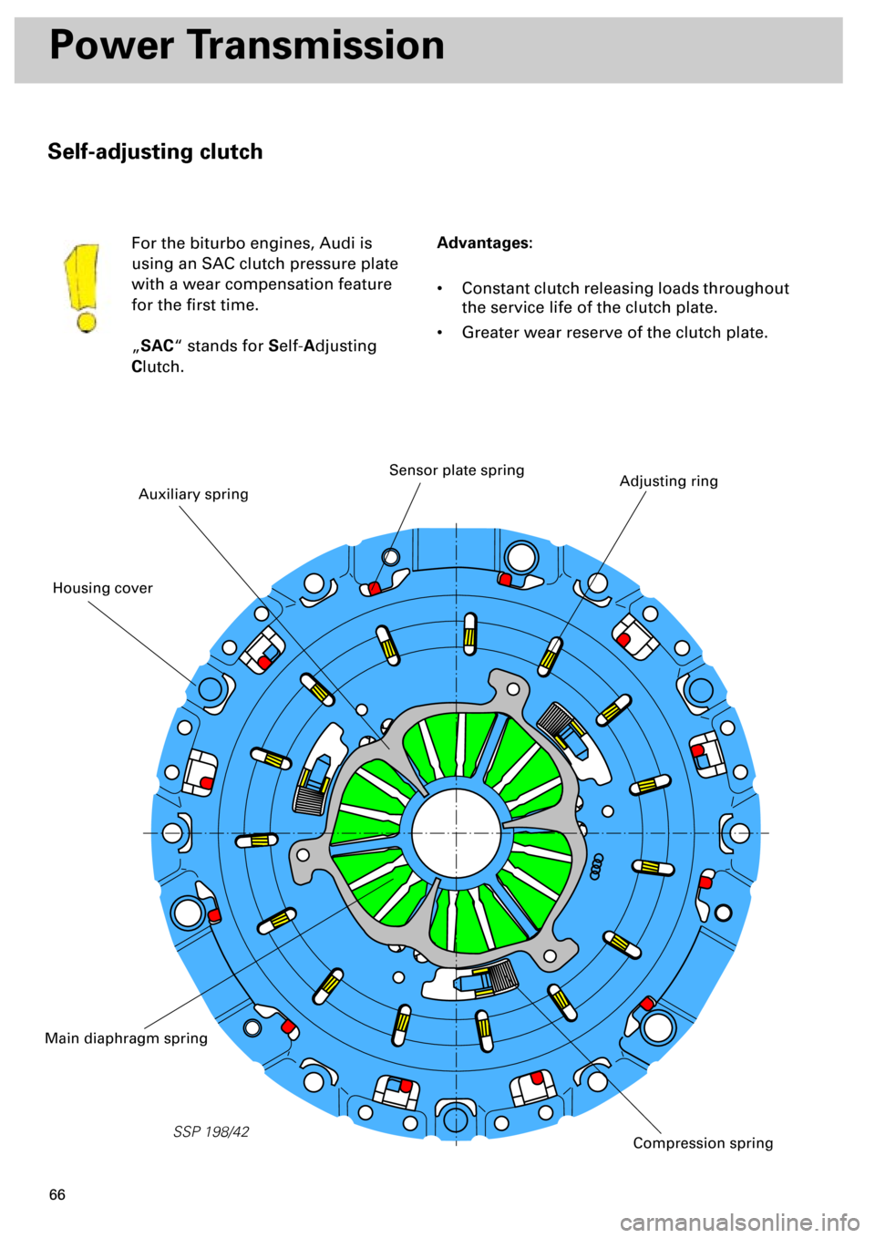
Self-adjusting clutch
Advantages:
• Constant clutch releasing loads throughout
the service life of the clutch plate.
• Greater wear reserve of the clutch plate. For the biturbo engines, Audi is
using an SAC clutch pressure plate
with a wear compensation feature
for the first time.
„
SAC
“ stands for
S
elf-
A
djusting
C
lutch.
SSP 198/42
Auxiliary spring
Adjusting ringSensor plate spring
Main diaphragm spring
Compression spring
Housing cover
Page 66 of 72
67
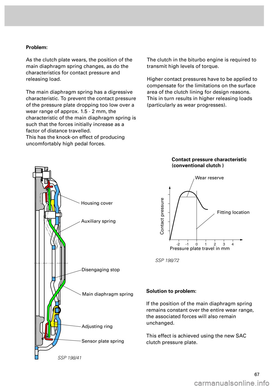
Problem:
As the clutch plate wears, the position of the
main diaphragm spring changes, as do the
characteristics for contact pressure and
releasing load.
The main diaphragm spring has a digressive
characteristic. To prevent the contact pressure
of the pressure plate dropping too low over a
wear range of approx. 1.5 - 2 mm, the
characteristic of the main diaphragm spring is
such that the forces initially increase as a
factor of distance travelled.
This has the knock-on effect of producing
uncomfortably high pedal forces.
The clutch in the biturbo engine is required to
transmit high levels of torque.
Higher contact pressures have to be applied to
compensate for the limitations on the surface
area of the clutch lining for design reasons.
This in turn results in higher releasing loads
(particularly as wear progresses).
Solution to problem:
If the position of the main diaphragm spring
remains constant over the entire wear range,
the associated forces will also remain
unchanged.
This effect is achieved using the new SAC
clutch pressure plate.
SSP 198/41
Housing cover
SSP 198/72
0 -1 -2 1 2 3 4
Pressure plate travel in mm
Contact pressure
Fitting location
Wear reserve
Contact pressure characteristic
(conventional clutch )
Sensor plate spring
Main diaphragm spring
Adjusting ring
Auxiliary spring
Disengaging stop
Page 70 of 72
71
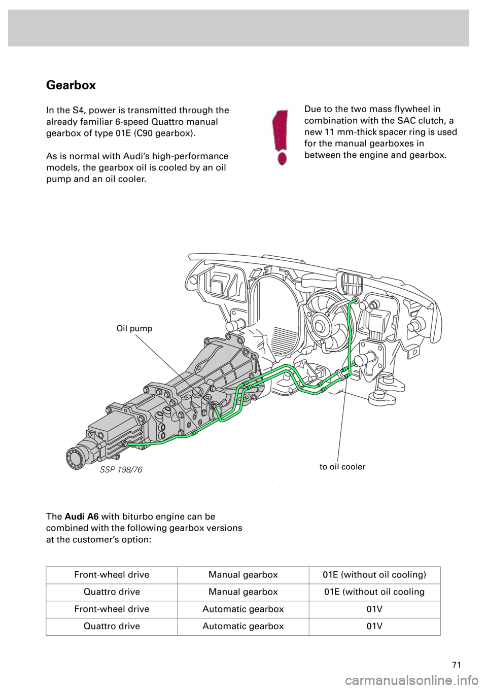
Gearbox
In the S4, power is transmitted through the
already familiar 6-speed Quattro manual
gearbox of type 01E (C90 gearbox).
As is normal with Audi’s high-performance
models, the gearbox oil is cooled by an oil
pump and an oil cooler.
The
Audi A6
with biturbo engine can be
combined with the following gearbox versions
at the customer’s option:
Front-wheel drive Manual gearbox 01E (without oil cooling)
Quattro drive Manual gearbox 01E (without oil cooling
Front-wheel drive Automatic gearbox 01V
Quattro drive Automatic gearbox 01V
Due to the two mass flywheel in
combination with the SAC clutch, a
new 11 mm-thick spacer ring is used
for the manual gearboxes in
between the engine and gearbox.
SSP 198/76
to oil cooler
Oil pump
Page 72 of 72
73
Dear reader,
With its innovative development of the new biturbo engine, AUDI has
achieved a further milestone in the field of engineering.
With this Self-study Programme you were able to familiarise yourself with
the technology of the biturbo.
In the course of work on our corporate identity (CI), the Self-study
Programme now has a new format. For example, the SSP number is
printed on the back page of the booklet so that you no longer need to take
the booklet out of the folder when searching for it.
Please fax us your suggestions for improving the Self-study Programmes
on +49 841-89-6367.
With the kind regards of your Technical Service Training Team