cooling AUDI S4 1998 B5 / 1.G Engine Manual
[x] Cancel search | Manufacturer: AUDI, Model Year: 1998, Model line: S4, Model: AUDI S4 1998 B5 / 1.GPages: 72, PDF Size: 3.25 MB
Page 3 of 72
3
This Self-study Programme provides you with information
regarding design and function.
The Self-study Programme is not a Workshop Manual!
Please refer to the Service Literature for all the relevant
maintenance and repair instructions.
Page
Engine .........................................................
Technical data, crankshaft, cylinder head,
camshaft timing, cooling circuit, engine
lubrication, overview of components, air ducting,
charging, exhaust system, pneumatically
controlled systems, charge pressure control, air
divert control in overrun, ACF system, crankcase
breather
4
Motronic ME 7.1 ..........................................
Subfunctions, system overview
31
Subsystems of the Motronic .....................
Torque-oriented engine management, torque-
oriented functional structure, Electronic throttle,
exhaust gas temperature control
33
Sensors .......................................................
Additional sensors of the Motronic
49
Auxiliary signals/interfaces ...................... 57
Functional diagram ..................................... 62
Self-diagnosis .............................................
Vehicle diagnosis, test and information system
VAS 5051, test box V.A.G 1598/31
64
Transmission ..............................................
Self-adjusting clutch, gearbox
66
Contents
Important!/Note!
New!
Page 9 of 72
9
SSP 198/03
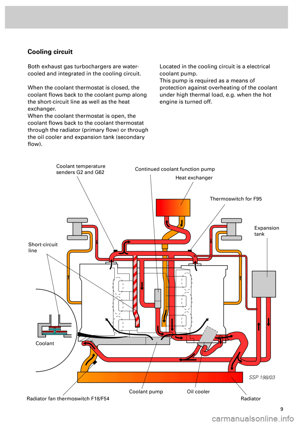
Cooling circuit
Both exhaust gas turbochargers are water-
cooled and integrated in the cooling circuit.
When the coolant thermostat is closed, the
coolant flows back to the coolant pump along
the short-circuit line as well as the heat
exchanger.
When the coolant thermostat is open, the
coolant flows back to the coolant thermostat
through the radiator (primary flow) or through
the oil cooler and expansion tank (secondary
flow).Located in the cooling circuit is a electrical
coolant pump.
This pump is required as a means of
protection against overheating of the coolant
under high thermal load, e.g. when the hot
engine is turned off.
Short-circuit
line
Continued coolant function pump
Heat exchanger
Coolant
Expansion
tank
Radiator fan thermoswitch F18/F54
Oil cooler
Radiator
Thermoswitch for F95
Coolant temperature
senders G2 and G62
Coolant pump
Page 10 of 72
10
SSP 198/10
Engine
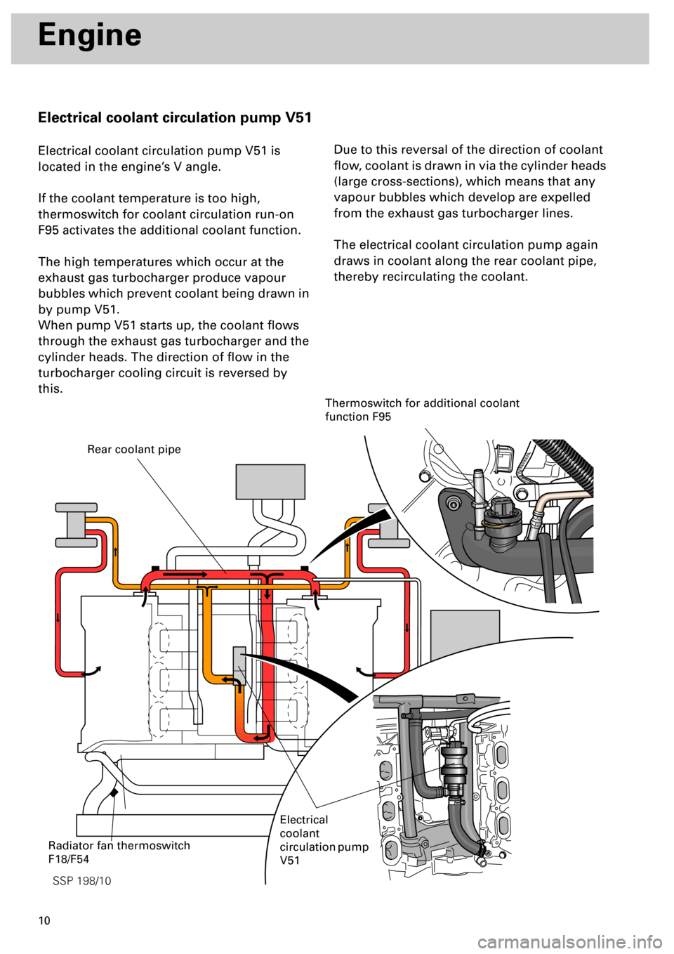
Electrical coolant circulation pump V51
Electrical coolant circulation pump V51 is
located in the engine’s V angle.
If the coolant temperature is too high,
thermoswitch for coolant circulation run-on
F95 activates the additional coolant function.
The high temperatures which occur at the
exhaust gas turbocharger produce vapour
bubbles which prevent coolant being drawn in
by pump V51.
When pump V51 starts up, the coolant flows
through the exhaust gas turbocharger and the
cylinder heads. The direction of flow in the
turbocharger cooling circuit is reversed by
this.Due to this reversal of the direction of coolant
flow, coolant is drawn in via the cylinder heads
(large cross-sections), which means that any
vapour bubbles which develop are expelled
from the exhaust gas turbocharger lines.
The electrical coolant circulation pump again
draws in coolant along the rear coolant pipe,
thereby recirculating the coolant.
Rear coolant pipe
Electrical
coolant
circulation pump
V51
Thermoswitch for additional coolant
function F95
Radiator fan thermoswitch
F18/F54
Page 15 of 72
16
Engine
The component parts of the oil circuit
is integrated in the primary flow. By increasing
the capacity and optimising the flow
resistance, the entire oil flow can be routed
through the oil cooler. Unlike the V6 naturally
aspirated engine, a bypass is not required.
The oil cooler ......
contains an oil retention valve, the filter
element, a bypass filter and the filter bypass
valve. The latter has the task of maintaining
engine lubrication via the bypass filter if the
filter element becomes clogged up or if the oil
has a high viscosity.
The oil filter ......
opens up the oil flow to the piston spray jets if
the oil pressure is greater than 1.8 bar.
Reason: at low oil viscosity and low engine
speeds, the oil pressure would otherwise drop
below the minimum permissible level. That
aside, piston cooling is not necessary at low
engine speeds.
The spray jets valve ......
SSP 198/57
Oil pressure control valve
Oil pressure limiting valve
Chain guard
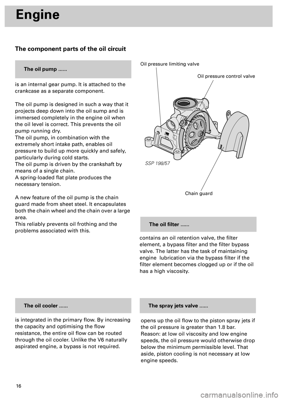
is an internal gear pump. It is attached to the
crankcase as a separate component.
The oil pump is designed in such a way that it
projects deep down into the oil sump and is
immersed completely in the engine oil when
the oil level is correct. This prevents the oil
pump running dry.
The oil pump, in combination with the
extremely short intake path, enables oil
pressure to build up more quickly and safely,
particularly during cold starts.
The oil pump is driven by the crankshaft by
means of a single chain.
A spring-loaded flat plate produces the
necessary tension.
A new feature of the oil pump is the chain
guard made from sheet steel. It encapsulates
both the chain wheel and the chain over a large
area.
This reliably prevents oil frothing and the
problems associated with this.
The oil pump ......
Page 18 of 72
19
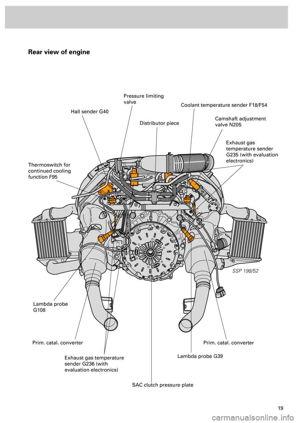
Rear view of engine
SSP 198/52
Hall sender G40
Thermoswitch for
continued cooling
function F95
Pressure limiting
valve
Distributor piece
Coolant temperature sender F18/F54
Camshaft adjustment
valve N205
Exhaust gas
temperature sender
G235 (with evaluation
electronics)
Lambda probe
G108
Exhaust gas temperature
sender G236 (with
evaluation electronics)Lambda probe G39
SAC clutch pressure plate
Prim. catal. converterPrim. catal. converter
Page 21 of 72
22
SSP 198/04
Engine
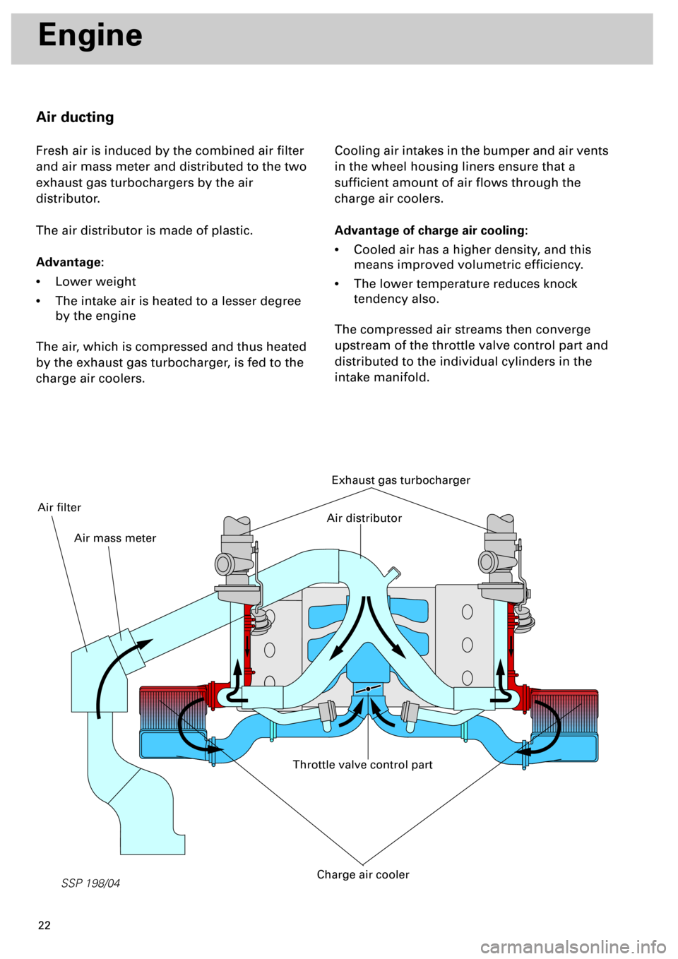
Air ducting
Fresh air is induced by the combined air filter
and air mass meter and distributed to the two
exhaust gas turbochargers by the air
distributor.
The air distributor is made of plastic.
Advantage:
•
Lower weight
•
The intake air is heated to a lesser degree
by the engine
The air, which is compressed and thus heated
by the exhaust gas turbocharger, is fed to the
charge air coolers.Cooling air intakes in the bumper and air vents
in the wheel housing liners ensure that a
sufficient amount of air flows through the
charge air coolers.
Advantage of charge air cooling:
•
Cooled air has a higher density, and this
means improved volumetric efficiency.
•
The lower temperature reduces knock
tendency also.
The compressed air streams then converge
upstream of the throttle valve control part and
distributed to the individual cylinders in the
intake manifold.
Exhaust gas turbocharger
Throttle valve control part
Charge air cooler
Air distributor
Air mass meter
Air filter
Page 70 of 72
71
Gearbox
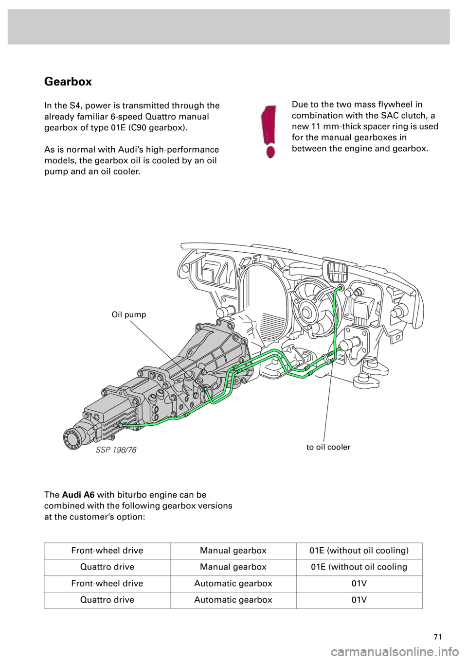
In the S4, power is transmitted through the
already familiar 6-speed Quattro manual
gearbox of type 01E (C90 gearbox).
As is normal with Audi’s high-performance
models, the gearbox oil is cooled by an oil
pump and an oil cooler.
The
Audi A6
with biturbo engine can be
combined with the following gearbox versions
at the customer’s option:
Front-wheel drive Manual gearbox 01E (without oil cooling)
Quattro drive Manual gearbox 01E (without oil cooling
Front-wheel drive Automatic gearbox 01V
Quattro drive Automatic gearbox 01V
Due to the two mass flywheel in
combination with the SAC clutch, a
new 11 mm-thick spacer ring is used
for the manual gearboxes in
between the engine and gearbox.
SSP 198/76
to oil cooler
Oil pump