engine coolant AUDI S4 1998 B5 / 1.G Engine Manual
[x] Cancel search | Manufacturer: AUDI, Model Year: 1998, Model line: S4, Model: AUDI S4 1998 B5 / 1.GPages: 72, PDF Size: 3.25 MB
Page 9 of 72
9
SSP 198/03
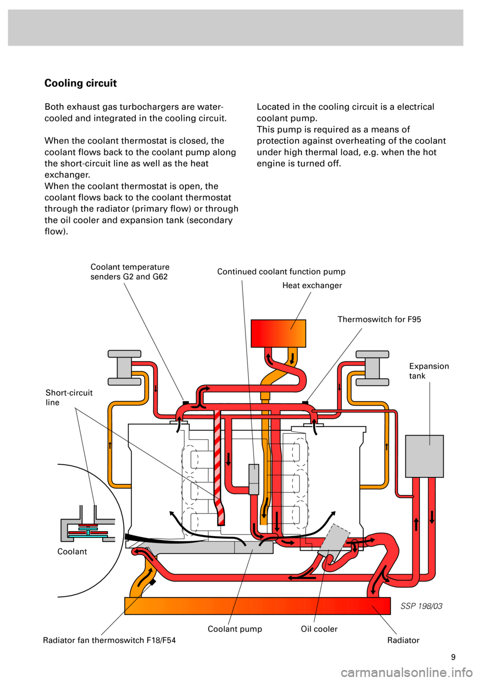
Cooling circuit
Both exhaust gas turbochargers are water-
cooled and integrated in the cooling circuit.
When the coolant thermostat is closed, the
coolant flows back to the coolant pump along
the short-circuit line as well as the heat
exchanger.
When the coolant thermostat is open, the
coolant flows back to the coolant thermostat
through the radiator (primary flow) or through
the oil cooler and expansion tank (secondary
flow).Located in the cooling circuit is a electrical
coolant pump.
This pump is required as a means of
protection against overheating of the coolant
under high thermal load, e.g. when the hot
engine is turned off.
Short-circuit
line
Continued coolant function pump
Heat exchanger
Coolant
Expansion
tank
Radiator fan thermoswitch F18/F54
Oil cooler
Radiator
Thermoswitch for F95
Coolant temperature
senders G2 and G62
Coolant pump
Page 10 of 72
10
SSP 198/10
Engine
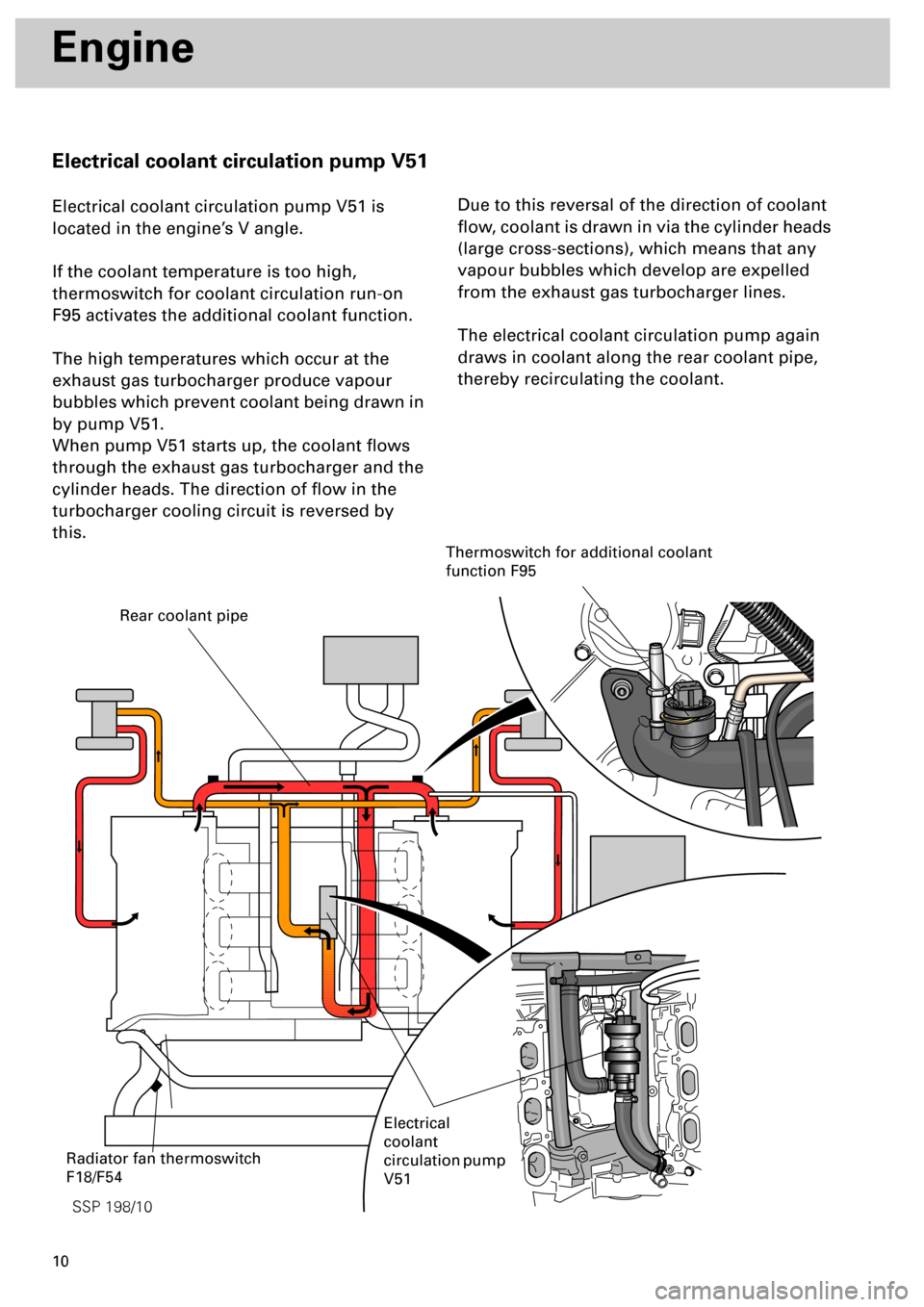
Electrical coolant circulation pump V51
Electrical coolant circulation pump V51 is
located in the engine’s V angle.
If the coolant temperature is too high,
thermoswitch for coolant circulation run-on
F95 activates the additional coolant function.
The high temperatures which occur at the
exhaust gas turbocharger produce vapour
bubbles which prevent coolant being drawn in
by pump V51.
When pump V51 starts up, the coolant flows
through the exhaust gas turbocharger and the
cylinder heads. The direction of flow in the
turbocharger cooling circuit is reversed by
this.Due to this reversal of the direction of coolant
flow, coolant is drawn in via the cylinder heads
(large cross-sections), which means that any
vapour bubbles which develop are expelled
from the exhaust gas turbocharger lines.
The electrical coolant circulation pump again
draws in coolant along the rear coolant pipe,
thereby recirculating the coolant.
Rear coolant pipe
Electrical
coolant
circulation pump
V51
Thermoswitch for additional coolant
function F95
Radiator fan thermoswitch
F18/F54
Page 12 of 72
12
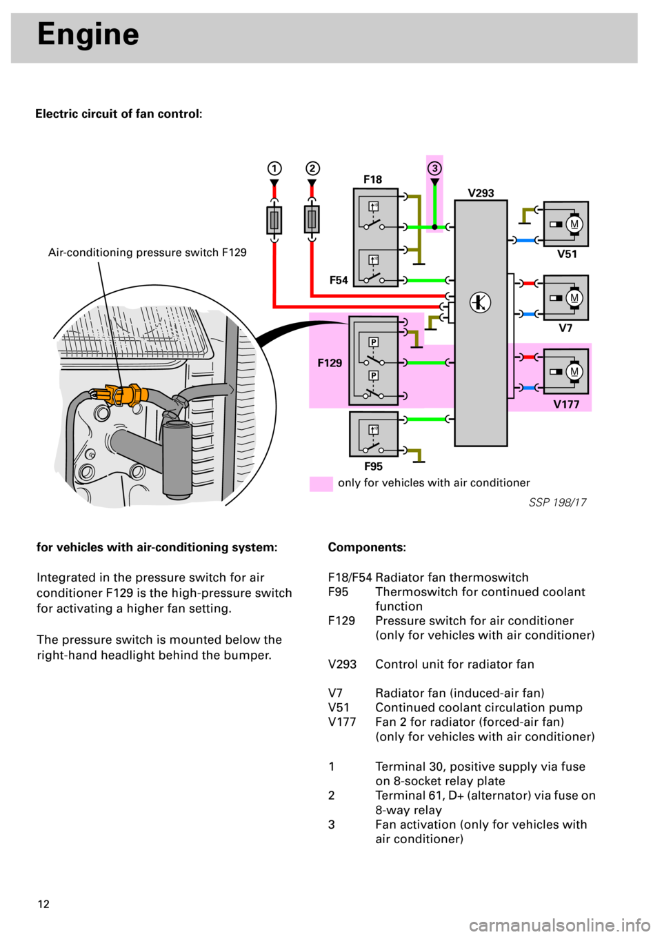
Electric circuit of fan control:
Engine
for vehicles with air-conditioning system:
Integrated in the pressure switch for air
conditioner F129 is the high-pressure switch
for activating a higher fan setting.
The pressure switch is mounted below the
right-hand headlight behind the bumper.
Components:
F18/F54 Radiator fan thermoswitch
F95 Thermoswitch for continued coolant
function
F129 Pressure switch for air conditioner
(only for vehicles with air conditioner)
V293 Control unit for radiator fan
V7 Radiator fan (induced-air fan)
V51 Continued coolant circulation pump
V177 Fan 2 for radiator (forced-air fan)
(only for vehicles with air conditioner)
1 Terminal 30, positive supply via fuse
on 8-socket relay plate
2 Terminal 61, D+ (alternator) via fuse on
8-way relay
3 Fan activation (only for vehicles with
air conditioner)
M_
V293 F18
F54
F129
V177V7 V51
M_
M_
SSP 198/17
*
*
F95
*
P
P
123
only for vehicles with air conditioner
Air-conditioning pressure switch F129
Page 13 of 72
13
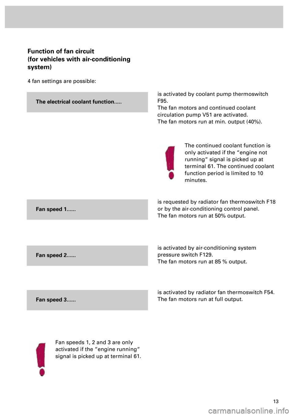
Function of fan circuit
(for vehicles with air-conditioning
system)
4 fan settings are possible:
is activated by coolant pump thermoswitch
F95.
The fan motors and continued coolant
circulation pump V51 are activated.
The fan motors run at min. output (40%).
is requested by radiator fan thermoswitch F18
or by the air-conditioning control panel.
The fan motors run at 50% output.
is activated by air-conditioning system
pressure switch F129.
The fan motors run at 85 % output.
is activated by radiator fan thermoswitch F54.
The fan motors run at full output.
Fan speeds 1, 2 and 3 are only
activated if the “engine running“
signal is picked up at terminal 61.
The electrical coolant function.....
The continued coolant function is
only activated if the “engine not
running“ signal is picked up at
terminal 61. The continued coolant
function period is limited to 10
minutes.
Fan speed 1......
Fan speed 2......
Fan speed 3......
Page 18 of 72
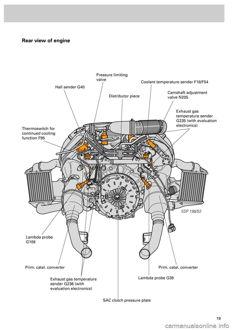
19
Rear view of engine
SSP 198/52
Hall sender G40
Thermoswitch for
continued cooling
function F95
Pressure limiting
valve
Distributor piece
Coolant temperature sender F18/F54
Camshaft adjustment
valve N205
Exhaust gas
temperature sender
G235 (with evaluation
electronics)
Lambda probe
G108
Exhaust gas temperature
sender G236 (with
evaluation electronics)Lambda probe G39
SAC clutch pressure plate
Prim. catal. converterPrim. catal. converter
Page 31 of 72
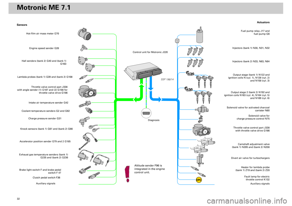
32
Actuators
Heater for lambda probe
(bank 1) Z19 and (bank 2) Z28
Divert air valve for turbochargers
Camshaft adjustment valve
(bank 1) N205 and (bank 2) N208
Throttle valve control part J338
with throttle valve drive G186
Solenoid valve for
charge pressure control N75
Solenoid valve for activated charcoal
canister N80
Output stage (bank 1) N122 and
ignition coils N (cyl. 1), N128 (cyl. 2)
and N158 (cyl. 3)Injectors (bank 1) N30, N31, N32
Fuel pump relay J17 and
fuel pump G6
Output stage 2 (bank 2) N192 and
ignition coils N163 (cyl. 4), N164 (cyl. 5)
and N189 (cyl. 6)
Fault lamp for electric
throttle control K132
Auxiliary signals
Sensors
Engine speed sender G28
Hall senders (bank 2) G40 and (bank 1)
G163
Lambda probes (bank 1) G39 and (bank 2) G108
Throttle valve control part J338
with angle sender (1) G187 and (2) G188 for
throttle valve drive G186
Intake air temperature sender G42
Coolant temperature senders G2 and G62
Charge pressure sender G31
Knock sensors (bank 1) G61 and (bank 2) G66Accelerator position sender G79 and 2 G185Exhaust gas temperature senders (bank 1)
G235 and (bank 2) G236Brake light switch F and brake pedal
switch F 47
Clutch pedal switch F36
Auxiliary signals
SSP 198/14
EPC
Injectors (bank 2) N33, N83, N84
Hot-film air mass meter G70
Control unit for Motronic J220
Altitude sender F96 is
integrated in the engine
control unit.
Diagnosis
Motronic ME 7.1
Page 56 of 72
57
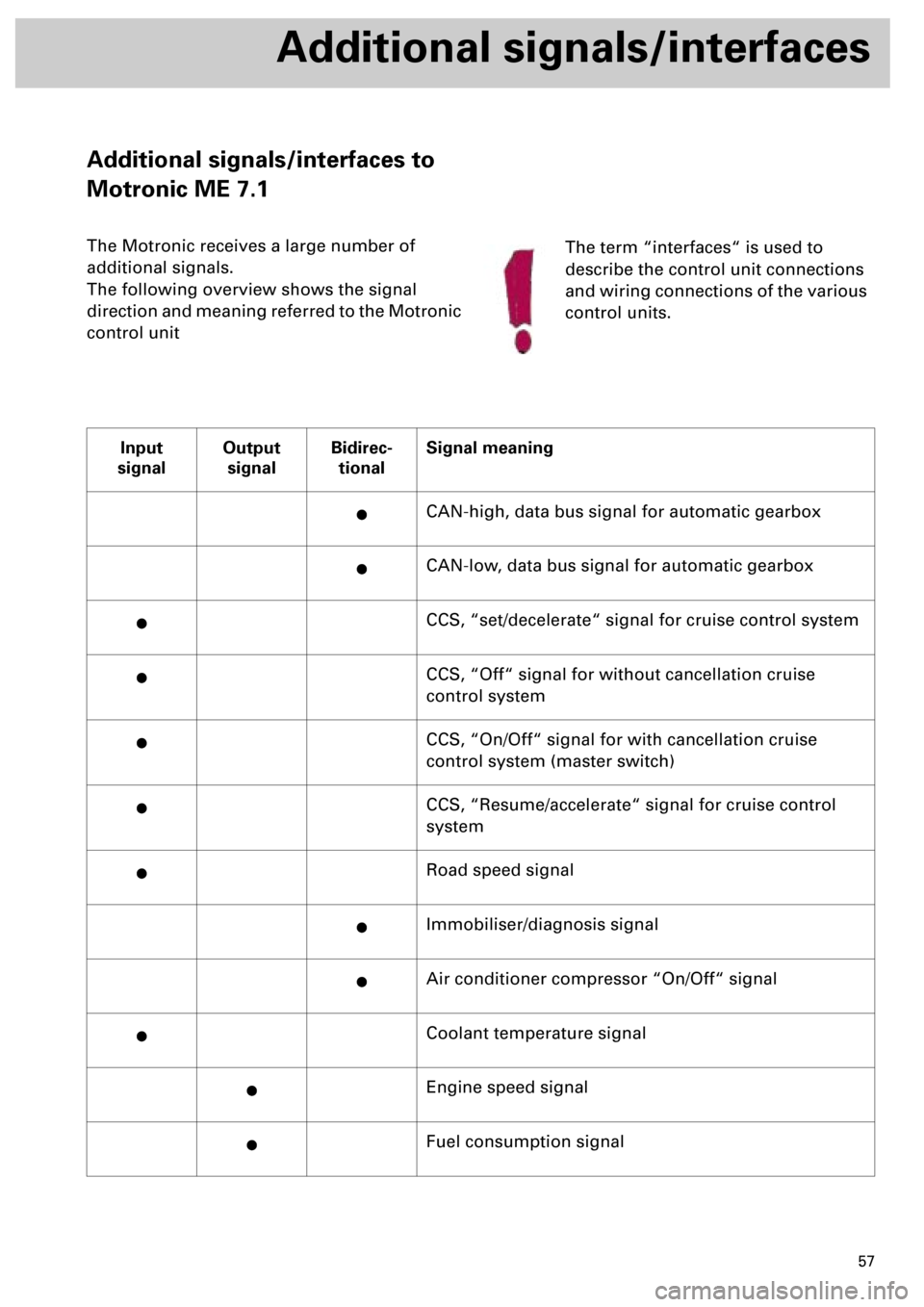
Additional signals/interfaces
Additional signals/interfaces to
Motronic ME 7.1
The Motronic receives a large number of
additional signals.
The following overview shows the signal
direction and meaning referred to the Motronic
control unit
Input
signalOutput
signalBidirec-
tionalSignal meaning
·CAN-high, data bus signal for automatic gearbox
·CAN-low, data bus signal for automatic gearbox
·CCS, “set/decelerate“ signal for cruise control system
·CCS, “Off“ signal for without cancellation cruise
control system
·CCS, “On/Off“ signal for with cancellation cruise
control system (master switch)
·CCS, “Resume/accelerate“ signal for cruise control
system
·Road speed signal
·Immobiliser/diagnosis signal
·Air conditioner compressor “On/Off“ signal
·Coolant temperature signal
·Engine speed signal
·Fuel consumption signal
The term “interfaces“ is used to
describe the control unit connections
and wiring connections of the various
control units.
Page 57 of 72
58
Additional signals/interfaces
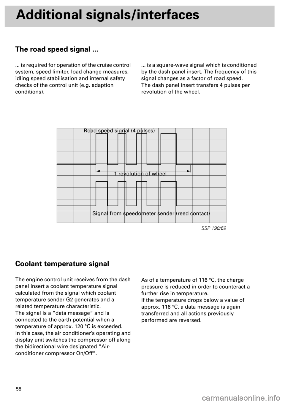
The road speed signal ...
... is required for operation of the cruise control
system, speed limiter, load change measures,
idling speed stabilisation and internal safety
checks of the control unit (e.g. adaption
conditions).... is a square-wave signal which is conditioned
by the dash panel insert. The frequency of this
signal changes as a factor of road speed.
The dash panel insert transfers 4 pulses per
revolution of the wheel.
Coolant temperature signal
The engine control unit receives from the dash
panel insert a coolant temperature signal
calculated from the signal which coolant
temperature sender G2 generates and a
related temperature characteristic.
The signal is a “data message“ and is
connected to the earth potential when a
temperature of approx. 120 °C is exceeded.
In this case, the air conditioner’s operating and
display unit switches the compressor off along
the bidirectional wire designated “Air-
conditioner compressor On/Off“.As of a temperature of 116 °C, the charge
pressure is reduced in order to counteract a
further rise in temperature.
If the temperature drops below a value of
approx. 116 °C, a data message is again
transferred and all actions previously
performed are reversed.
SSP 198/69
1 revolution of wheel Road speed signal (4 pulses)
Signal from speedometer sender (reed contact)
Page 61 of 72
62
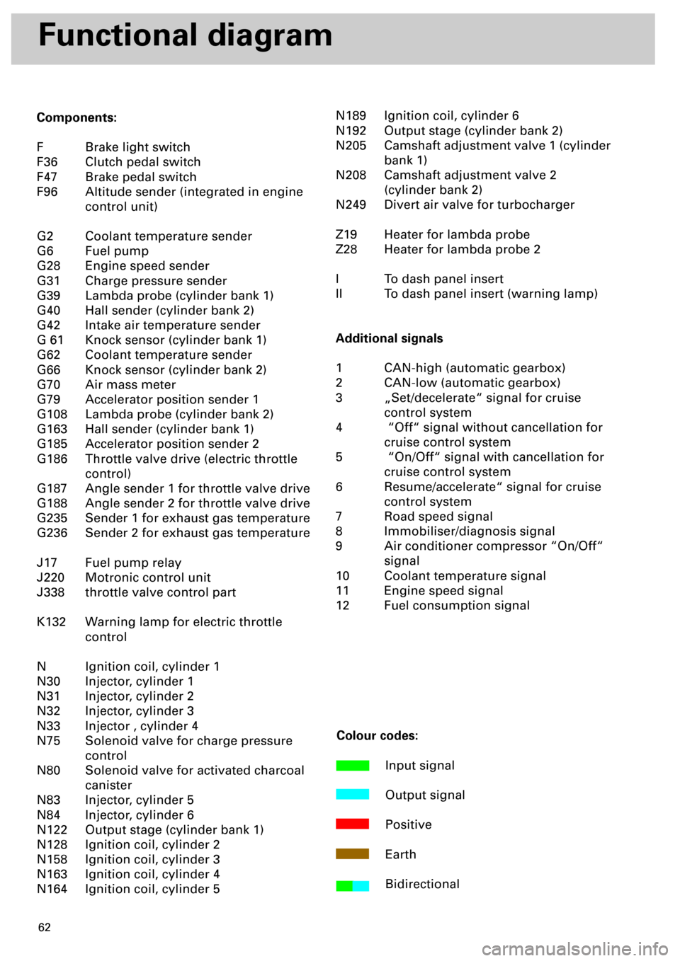
Functional diagram
Components:
F Brake light switch
F36 Clutch pedal switch
F47 Brake pedal switch
F96 Altitude sender (integrated in engine
control unit)
G2 Coolant temperature sender
G6 Fuel pump
G28 Engine speed sender
G31 Charge pressure sender
G39 Lambda probe (cylinder bank 1)
G40 Hall sender (cylinder bank 2)
G42 Intake air temperature sender
G 61 Knock sensor (cylinder bank 1)
G62 Coolant temperature sender
G66 Knock sensor (cylinder bank 2)
G70 Air mass meter
G79 Accelerator position sender 1
G108 Lambda probe (cylinder bank 2)
G163 Hall sender (cylinder bank 1)
G185 Accelerator position sender 2
G186 Throttle valve drive (electric throttle
control)
G187 Angle sender 1 for throttle valve drive
G188 Angle sender 2 for throttle valve drive
G235 Sender 1 for exhaust gas temperature
G236 Sender 2 for exhaust gas temperature
J17 Fuel pump relay
J220 Motronic control unit
J338 throttle valve control part
K132 Warning lamp for electric throttle
control
N Ignition coil, cylinder 1
N30 Injector, cylinder 1
N31 Injector, cylinder 2
N32 Injector, cylinder 3
N33 Injector , cylinder 4
N75 Solenoid valve for charge pressure
control
N80 Solenoid valve for activated charcoal
canister
N83 Injector, cylinder 5
N84 Injector, cylinder 6
N122 Output stage (cylinder bank 1)
N128 Ignition coil, cylinder 2
N158 Ignition coil, cylinder 3
N163 Ignition coil, cylinder 4
N164 Ignition coil, cylinder 5N189 Ignition coil, cylinder 6
N192 Output stage (cylinder bank 2)
N205 Camshaft adjustment valve 1 (cylinder
bank 1)
N208 Camshaft adjustment valve 2
(cylinder bank 2)
N249 Divert air valve for turbocharger
Z19 Heater for lambda probe
Z28 Heater for lambda probe 2
I To dash panel insert
II To dash panel insert (warning lamp)
Additional signals
1 CAN-high (automatic gearbox)
2 CAN-low (automatic gearbox)
3 „Set/decelerate“ signal for cruise
control system
4 “Off“ signal without cancellation for
cruise control system
5 “On/Off“ signal with cancellation for
cruise control system
6 Resume/accelerate“ signal for cruise
control system
7 Road speed signal
8 Immobiliser/diagnosis signal
9 Air conditioner compressor “On/Off“
signal
10 Coolant temperature signal
11 Engine speed signal
12 Fuel consumption signal
Colour codes:
Input signal
Output signal
Positive
Earth
Bidirectional