light AUDI S4 1998 B5 / 1.G Engine Manual
[x] Cancel search | Manufacturer: AUDI, Model Year: 1998, Model line: S4, Model: AUDI S4 1998 B5 / 1.GPages: 72, PDF Size: 3.25 MB
Page 12 of 72
12
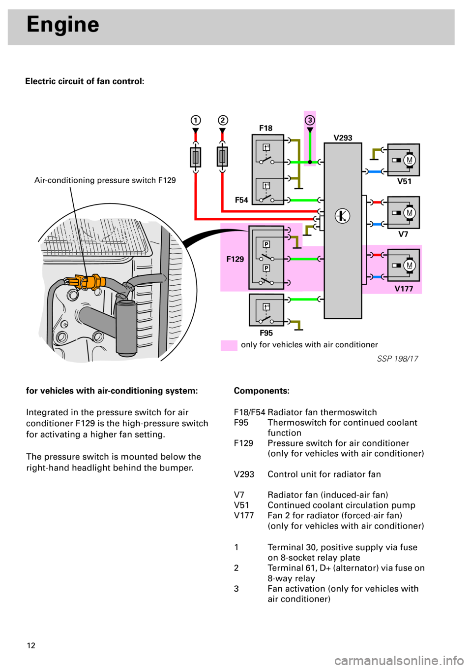
Electric circuit of fan control:
Engine
for vehicles with air-conditioning system:
Integrated in the pressure switch for air
conditioner F129 is the high-pressure switch
for activating a higher fan setting.
The pressure switch is mounted below the
right-hand headlight behind the bumper.
Components:
F18/F54 Radiator fan thermoswitch
F95 Thermoswitch for continued coolant
function
F129 Pressure switch for air conditioner
(only for vehicles with air conditioner)
V293 Control unit for radiator fan
V7 Radiator fan (induced-air fan)
V51 Continued coolant circulation pump
V177 Fan 2 for radiator (forced-air fan)
(only for vehicles with air conditioner)
1 Terminal 30, positive supply via fuse
on 8-socket relay plate
2 Terminal 61, D+ (alternator) via fuse on
8-way relay
3 Fan activation (only for vehicles with
air conditioner)
M_
V293 F18
F54
F129
V177V7 V51
M_
M_
SSP 198/17
*
*
F95
*
P
P
123
only for vehicles with air conditioner
Air-conditioning pressure switch F129
Page 31 of 72
32
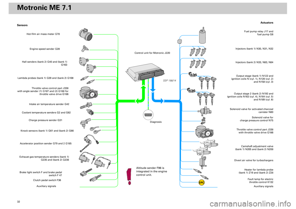
Actuators
Heater for lambda probe
(bank 1) Z19 and (bank 2) Z28
Divert air valve for turbochargers
Camshaft adjustment valve
(bank 1) N205 and (bank 2) N208
Throttle valve control part J338
with throttle valve drive G186
Solenoid valve for
charge pressure control N75
Solenoid valve for activated charcoal
canister N80
Output stage (bank 1) N122 and
ignition coils N (cyl. 1), N128 (cyl. 2)
and N158 (cyl. 3)Injectors (bank 1) N30, N31, N32
Fuel pump relay J17 and
fuel pump G6
Output stage 2 (bank 2) N192 and
ignition coils N163 (cyl. 4), N164 (cyl. 5)
and N189 (cyl. 6)
Fault lamp for electric
throttle control K132
Auxiliary signals
Sensors
Engine speed sender G28
Hall senders (bank 2) G40 and (bank 1)
G163
Lambda probes (bank 1) G39 and (bank 2) G108
Throttle valve control part J338
with angle sender (1) G187 and (2) G188 for
throttle valve drive G186
Intake air temperature sender G42
Coolant temperature senders G2 and G62
Charge pressure sender G31
Knock sensors (bank 1) G61 and (bank 2) G66Accelerator position sender G79 and 2 G185Exhaust gas temperature senders (bank 1)
G235 and (bank 2) G236Brake light switch F and brake pedal
switch F 47
Clutch pedal switch F36
Auxiliary signals
SSP 198/14
EPC
Injectors (bank 2) N33, N83, N84
Hot-film air mass meter G70
Control unit for Motronic J220
Altitude sender F96 is
integrated in the engine
control unit.
Diagnosis
Motronic ME 7.1
Page 38 of 72
39
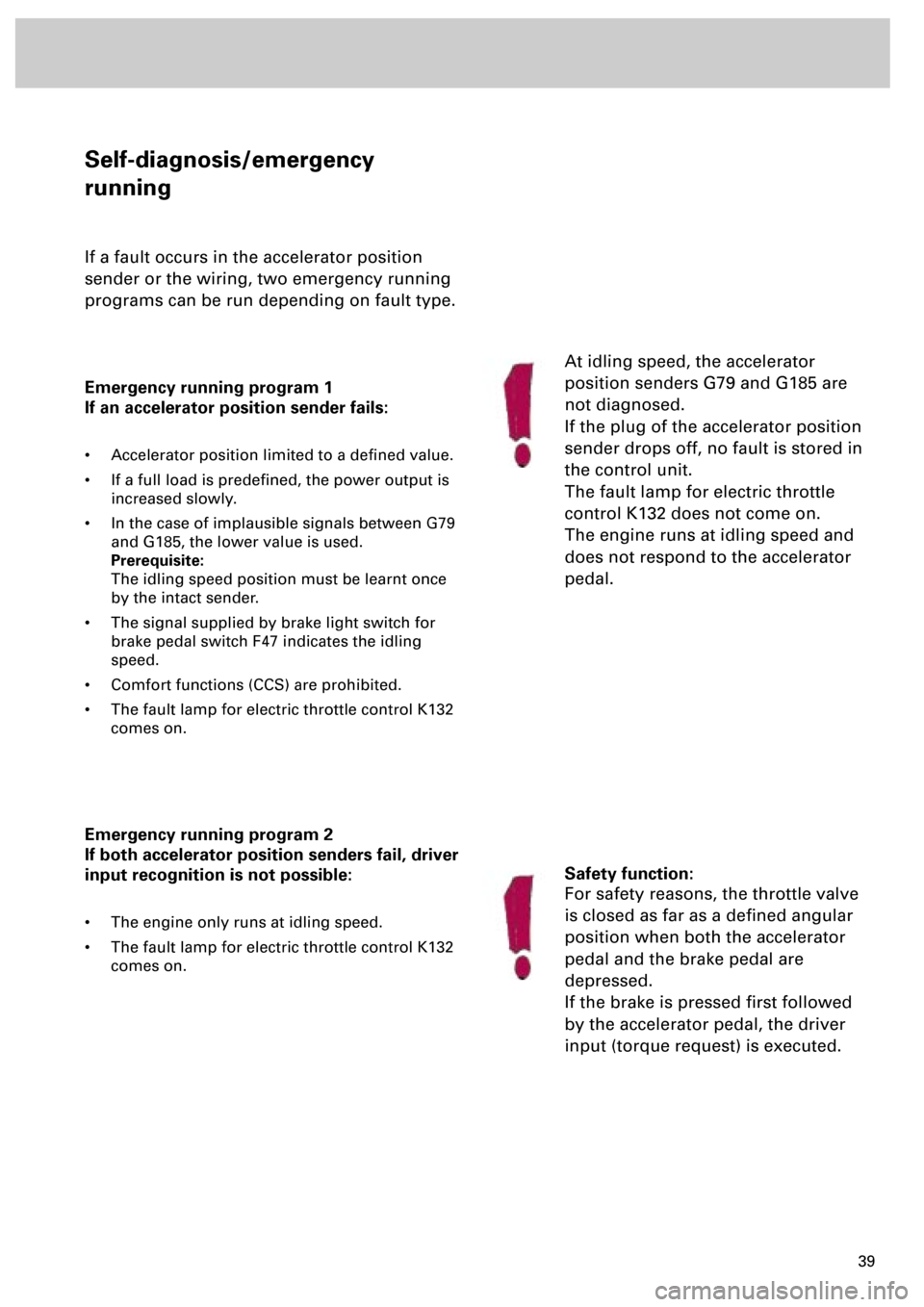
Self-diagnosis/emergency
running
If a fault occurs in the accelerator position
sender or the wiring, two emergency running
programs can be run depending on fault type.
Emergency running program 1
If an accelerator position sender fails:
• Accelerator position limited to a defined value.
• If a full load is predefined, the power output is
increased slowly.
• In the case of implausible signals between G79
and G185, the lower value is used.
Prerequisite:
The idling speed position must be learnt once
by the intact sender.
• The signal supplied by brake light switch for
brake pedal switch F47 indicates the idling
speed.
• Comfort functions (CCS) are prohibited.
• The fault lamp for electric throttle control K132
comes on.
Emergency running program 2
If both accelerator position senders fail, driver
input recognition is not possible:
• The engine only runs at idling speed.
• The fault lamp for electric throttle control K132
comes on.
At idling speed, the accelerator
position senders G79 and G185 are
not diagnosed.
If the plug of the accelerator position
sender drops off, no fault is stored in
the control unit.
The fault lamp for electric throttle
control K132 does not come on.
The engine runs at idling speed and
does not respond to the accelerator
pedal.
Safety function:
For safety reasons, the throttle valve
is closed as far as a defined angular
position when both the accelerator
pedal and the brake pedal are
depressed.
If the brake is pressed first followed
by the accelerator pedal, the driver
input (torque request) is executed.
Page 44 of 72
45
SSP 198/34
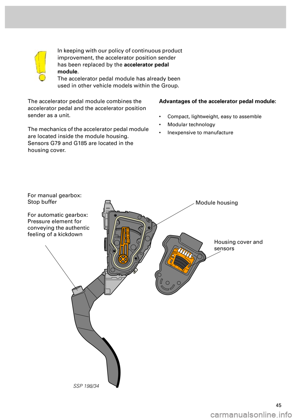
The accelerator pedal module combines the
accelerator pedal and the accelerator position
sender as a unit.
The mechanics of the accelerator pedal module
are located inside the module housing.
Sensors G79 and G185 are located in the
housing cover.In keeping with our policy of continuous product
improvement, the accelerator position sender
has been replaced by the
accelerator pedal
module
.
The accelerator pedal module has already been
used in other vehicle models within the Group.
Advantages of the accelerator pedal module:
• Compact, lightweight, easy to assemble
• Modular technology
• Inexpensive to manufacture
Module housing
Housing cover and
sensors
For manual gearbox:
Stop buffer
For automatic gearbox:
Pressure element for
conveying the authentic
feeling of a kickdown
Page 55 of 72
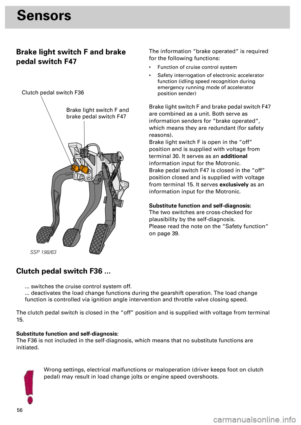
56
Sensors
Brake light switch F and brake
pedal switch F47The information “brake operated“ is required
for the following functions:
• Function of cruise control system
• Safety interrogation of electronic accelerator
function (idling speed recognition during
emergency running mode of accelerator
position sender)
Brake light switch F and brake pedal switch F47
are combined as a unit. Both serve as
information senders for “brake operated“,
which means they are redundant (for safety
reasons).
Brake light switch F is open in the “off”
position and is supplied with voltage from
terminal 30. It serves as an additional
information input for the Motronic.
Brake pedal switch F47 is closed in the “off”
position closed and is supplied with voltage
from terminal 15. It serves exclusively as an
information input for the Motronic.
Substitute function and self-diagnosis:
The two switches are cross-checked for
plausibility by the self-diagnosis.
Please read the note on the “Safety function“
on page 39.
Clutch pedal switch F36 ...
Wrong settings, electrical malfunctions or maloperation (driver keeps foot on clutch
pedal) may result in load change jolts or engine speed overshoots.
... switches the cruise control system off.
... deactivates the load change functions during the gearshift operation. The load change
function is controlled via ignition angle intervention and throttle valve closing speed.
The clutch pedal switch is closed in the “off” position and is supplied with voltage from terminal
15.
Substitute function and self-diagnosis:
The F36 is not included in the self-diagnosis, which means that no substitute functions are
initiated.
SSP 198/63
Brake light switch F and
brake pedal switch F47
Clutch pedal switch F36
Page 61 of 72
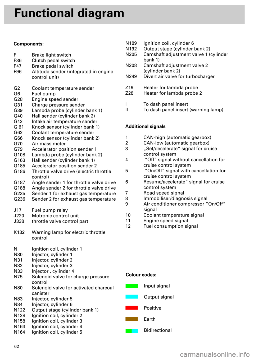
62
Functional diagram
Components:
F Brake light switch
F36 Clutch pedal switch
F47 Brake pedal switch
F96 Altitude sender (integrated in engine
control unit)
G2 Coolant temperature sender
G6 Fuel pump
G28 Engine speed sender
G31 Charge pressure sender
G39 Lambda probe (cylinder bank 1)
G40 Hall sender (cylinder bank 2)
G42 Intake air temperature sender
G 61 Knock sensor (cylinder bank 1)
G62 Coolant temperature sender
G66 Knock sensor (cylinder bank 2)
G70 Air mass meter
G79 Accelerator position sender 1
G108 Lambda probe (cylinder bank 2)
G163 Hall sender (cylinder bank 1)
G185 Accelerator position sender 2
G186 Throttle valve drive (electric throttle
control)
G187 Angle sender 1 for throttle valve drive
G188 Angle sender 2 for throttle valve drive
G235 Sender 1 for exhaust gas temperature
G236 Sender 2 for exhaust gas temperature
J17 Fuel pump relay
J220 Motronic control unit
J338 throttle valve control part
K132 Warning lamp for electric throttle
control
N Ignition coil, cylinder 1
N30 Injector, cylinder 1
N31 Injector, cylinder 2
N32 Injector, cylinder 3
N33 Injector , cylinder 4
N75 Solenoid valve for charge pressure
control
N80 Solenoid valve for activated charcoal
canister
N83 Injector, cylinder 5
N84 Injector, cylinder 6
N122 Output stage (cylinder bank 1)
N128 Ignition coil, cylinder 2
N158 Ignition coil, cylinder 3
N163 Ignition coil, cylinder 4
N164 Ignition coil, cylinder 5N189 Ignition coil, cylinder 6
N192 Output stage (cylinder bank 2)
N205 Camshaft adjustment valve 1 (cylinder
bank 1)
N208 Camshaft adjustment valve 2
(cylinder bank 2)
N249 Divert air valve for turbocharger
Z19 Heater for lambda probe
Z28 Heater for lambda probe 2
I To dash panel insert
II To dash panel insert (warning lamp)
Additional signals
1 CAN-high (automatic gearbox)
2 CAN-low (automatic gearbox)
3 „Set/decelerate“ signal for cruise
control system
4 “Off“ signal without cancellation for
cruise control system
5 “On/Off“ signal with cancellation for
cruise control system
6 Resume/accelerate“ signal for cruise
control system
7 Road speed signal
8 Immobiliser/diagnosis signal
9 Air conditioner compressor “On/Off“
signal
10 Coolant temperature signal
11 Engine speed signal
12 Fuel consumption signal
Colour codes:
Input signal
Output signal
Positive
Earth
Bidirectional
Page 62 of 72
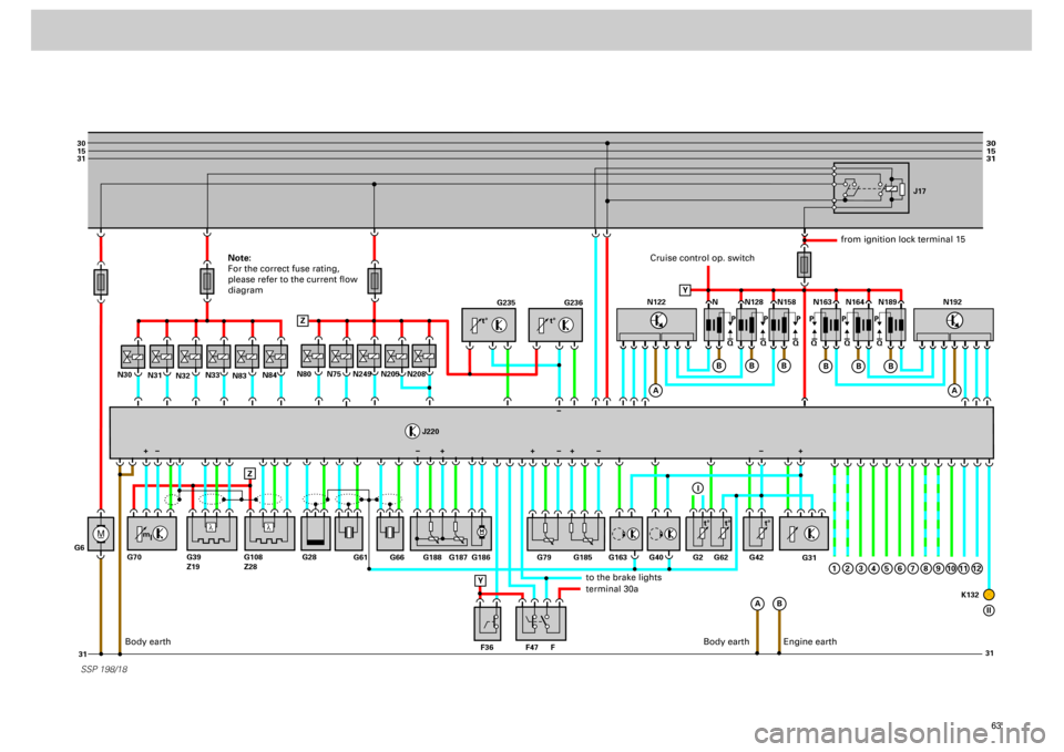
63
M
30
15
31
31 31
30
15
31
_
G6N31
N32N33N80
J220
N83N84
N30
N75
N249
N205
N208
SSP 198/18
G235
G236
G31
N N128J17
N158 N163 N164 N189
Q PPPPPP
QQ QQQ
A
A
B Z
ZB
B
B
N122
A
B
B
B
1
N192
G61
G66 G188 G187 G186 G79
F47 F36 FG163 G40 G62G2 G42
K132 G185
G28 G70 G39
Z19G108
Z28
Y
+
Y
I
2
3
4
5
6
7
8
9
10
11
12
II
l
l
t° t°
m
lt° t° t°
+++ +
Cruise control op. switch
from ignition lock terminal 15
to the brake lightsterminal 30a
Body earth
Engine earth
Note:
For the correct fuse rating,
please refer to the current flow
diagram
Body earth