service AUDI S4 1998 B5 / 1.G Engine Manual
[x] Cancel search | Manufacturer: AUDI, Model Year: 1998, Model line: S4, Model: AUDI S4 1998 B5 / 1.GPages: 72, PDF Size: 3.25 MB
Page 1 of 72

Service.
For internal use only
198
All rights reserved. Subject
to change.
AUDI AG
Dept.I/GS-5
D-85045 Ingolstadt
Fax +49.841/89-6367
740.2810.17.20
Technical status: 01/98
Printed in Germany
The 2.7-litre V6 Biturbo
Design and Function
Self-study Programme 198
Page 3 of 72
3
This Self-study Programme provides you with information
regarding design and function.
The Self-study Programme is not a Workshop Manual!
Please refer to the Service Literature for all the relevant
maintenance and repair instructions.
Page
Engine .........................................................
Technical data, crankshaft, cylinder head,
camshaft timing, cooling circuit, engine
lubrication, overview of components, air ducting,
charging, exhaust system, pneumatically
controlled systems, charge pressure control, air
divert control in overrun, ACF system, crankcase
breather
4
Motronic ME 7.1 ..........................................
Subfunctions, system overview
31
Subsystems of the Motronic .....................
Torque-oriented engine management, torque-
oriented functional structure, Electronic throttle,
exhaust gas temperature control
33
Sensors .......................................................
Additional sensors of the Motronic
49
Auxiliary signals/interfaces ...................... 57
Functional diagram ..................................... 62
Self-diagnosis .............................................
Vehicle diagnosis, test and information system
VAS 5051, test box V.A.G 1598/31
64
Transmission ..............................................
Self-adjusting clutch, gearbox
66
Contents
Important!/Note!
New!
Page 22 of 72
23
SSP 198/32
Charging
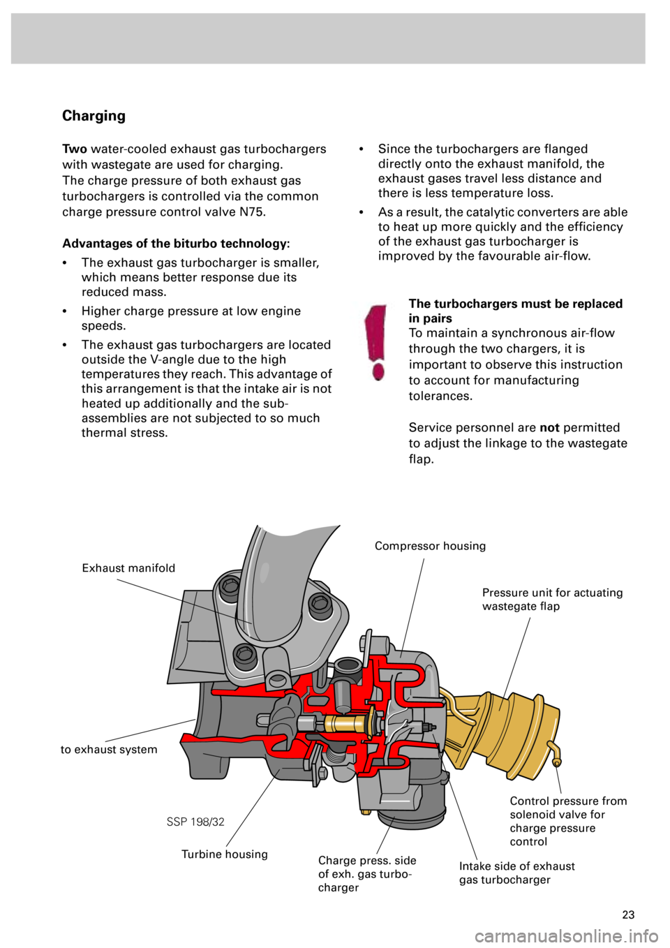
Two
water-cooled exhaust gas turbochargers
with wastegate are used for charging.
The charge pressure of both exhaust gas
turbochargers is controlled via the common
charge pressure control valve N75.
Advantages of the biturbo technology:
•
The exhaust gas turbocharger is smaller,
which means better response due its
reduced mass.
•
Higher charge pressure at low engine
speeds.
•
The exhaust gas turbochargers are located
outside the V-angle due to the high
temperatures they reach. This advantage of
this arrangement is that the intake air is not
heated up additionally and the sub-
assemblies are not subjected to so much
thermal stress.
•
Since the turbochargers are flanged
directly onto the exhaust manifold, the
exhaust gases travel less distance and
there is less temperature loss.
•
As a result, the catalytic converters are able
to heat up more quickly and the efficiency
of the exhaust gas turbocharger is
improved by the favourable air-flow.
Intake side of exhaust
gas turbocharger
Charge press. side
of exh. gas turbo-
charger
Exhaust manifold
to exhaust system
Pressure unit for actuating
wastegate flap
Control pressure from
solenoid valve for
charge pressure
control
The turbochargers must be replaced
in pairs
To maintain a synchronous air-flow
through the two chargers, it is
important to observe this instruction
to account for manufacturing
tolerances.
Service personnel are
not
permitted
to adjust the linkage to the wastegate
flap.
Turbine housing
Compressor housing
Page 23 of 72
24
SSP 198/33
Engine
A new generation of probes is used
in this engine.
The “planar lambda probe“ is an
improvement on the finger-type
lambda probe (refer to chapter on
“Sensors”).
Advantage:
•
Short warm-up time
•
Less heating energy demand
•
Long service life
•
More stable control
characteristic
Exhaust system
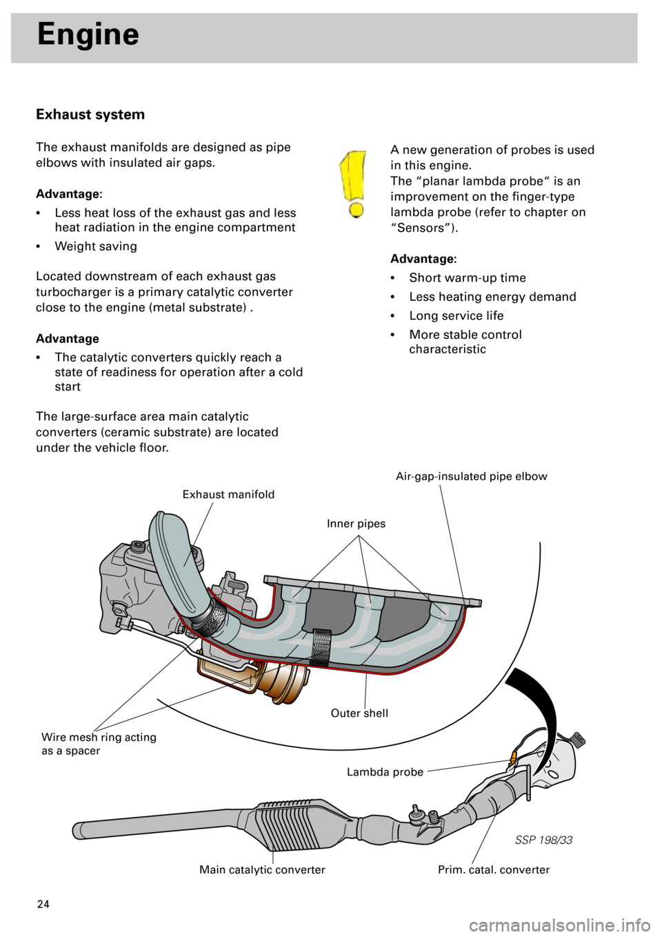
The exhaust manifolds are designed as pipe
elbows with insulated air gaps.
Advantage:
•
Less heat loss of the exhaust gas and less
heat radiation in the engine compartment
•
Weight saving
Located downstream of each exhaust gas
turbocharger is a primary catalytic converter
close to the engine (metal substrate) .
Advantage
•
The catalytic converters quickly reach a
state of readiness for operation after a cold
start
The large-surface area main catalytic
converters (ceramic substrate) are located
under the vehicle floor.
Lambda probe
Prim. catal. converterMain catalytic converter
Exhaust manifold
Wire mesh ring acting
as a spacer
Air-gap-insulated pipe elbow
Outer shell
Inner pipes
Page 51 of 72
52
Sensors
Lambda probes G39 and G108
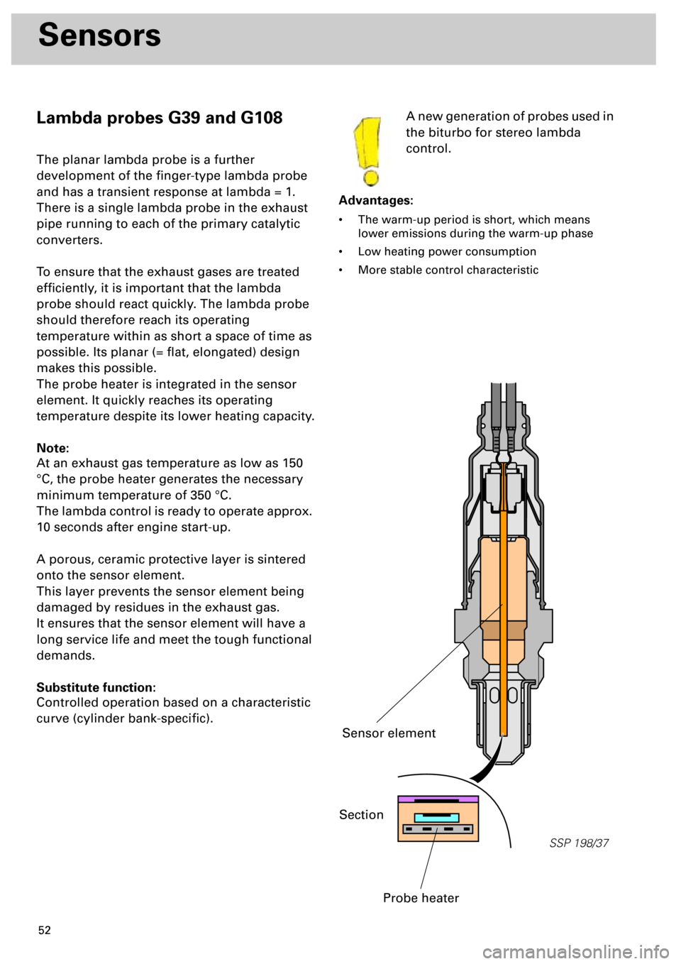
The planar lambda probe is a further
development of the finger-type lambda probe
and has a transient response at lambda = 1.
There is a single lambda probe in the exhaust
pipe running to each of the primary catalytic
converters.
To ensure that the exhaust gases are treated
efficiently, it is important that the lambda
probe should react quickly. The lambda probe
should therefore reach its operating
temperature within as short a space of time as
possible. Its planar (= flat, elongated) design
makes this possible.
The probe heater is integrated in the sensor
element. It quickly reaches its operating
temperature despite its lower heating capacity.
Note:
At an exhaust gas temperature as low as 150
°C, the probe heater generates the necessary
minimum temperature of 350 °C.
The lambda control is ready to operate approx.
10 seconds after engine start-up.
A porous, ceramic protective layer is sintered
onto the sensor element.
This layer prevents the sensor element being
damaged by residues in the exhaust gas.
It ensures that the sensor element will have a
long service life and meet the tough functional
demands.
Substitute function:
Controlled operation based on a characteristic
curve (cylinder bank-specific).A new generation of probes used in
the biturbo for stereo lambda
control.
Advantages:
• The warm-up period is short, which means
lower emissions during the warm-up phase
• Low heating power consumption
• More stable control characteristic
SSP 198/37
Section
Probe heater
Sensor element
Page 65 of 72
66
Power Transmission
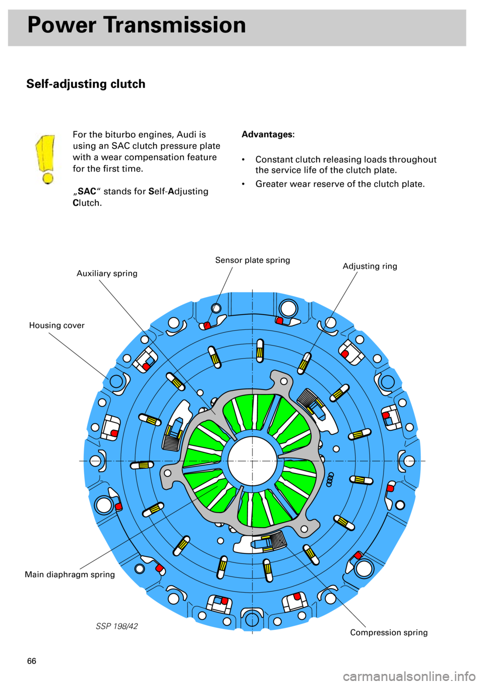
Self-adjusting clutch
Advantages:
• Constant clutch releasing loads throughout
the service life of the clutch plate.
• Greater wear reserve of the clutch plate. For the biturbo engines, Audi is
using an SAC clutch pressure plate
with a wear compensation feature
for the first time.
„
SAC
“ stands for
S
elf-
A
djusting
C
lutch.
SSP 198/42
Auxiliary spring
Adjusting ringSensor plate spring
Main diaphragm spring
Compression spring
Housing cover
Page 72 of 72

73
Dear reader,
With its innovative development of the new biturbo engine, AUDI has
achieved a further milestone in the field of engineering.
With this Self-study Programme you were able to familiarise yourself with
the technology of the biturbo.
In the course of work on our corporate identity (CI), the Self-study
Programme now has a new format. For example, the SSP number is
printed on the back page of the booklet so that you no longer need to take
the booklet out of the folder when searching for it.
Please fax us your suggestions for improving the Self-study Programmes
on +49 841-89-6367.
With the kind regards of your Technical Service Training Team