glove box AUDI S4 2008 Owners Manual
[x] Cancel search | Manufacturer: AUDI, Model Year: 2008, Model line: S4, Model: AUDI S4 2008Pages: 342, PDF Size: 15.01 MB
Page 11 of 342
Controls and displays9
Controls
Safety
Driving tips
General maintenance
Self-help
Technical data
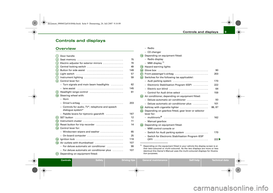
Controls and displaysOverview
Door handle
Seat memory . . . . . . . . . . . . . . . . . . . . . . . . . . . . . . . . . .
Electric adjuster for exterior mirrors . . . . . . . . . . . . . . .
Central locking switch . . . . . . . . . . . . . . . . . . . . . . . . . . .
Button for side assist . . . . . . . . . . . . . . . . . . . . . . . . . . .
Light switch . . . . . . . . . . . . . . . . . . . . . . . . . . . . . . . . . . .
Instrument lighting . . . . . . . . . . . . . . . . . . . . . . . . . . . . .
Control lever for:
−Turn signals and main beam headlights . . . . . . . . .
− lane assist . . . . . . . . . . . . . . . . . . . . . . . . . . . . . . . . . .
Headlight range control . . . . . . . . . . . . . . . . . . . . . . . . .
Steering wheel with:
− Horn
− Driver's airbag . . . . . . . . . . . . . . . . . . . . . . . . . . . . . . .
− Controls for audio, TV*, telephone and speech
dialogue system*
− Paddle levers for tiptronic gearshift . . . . . . . . . . . . .
SET button . . . . . . . . . . . . . . . . . . . . . . . . . . . . . . . . . . . .
Instrument cluster . . . . . . . . . . . . . . . . . . . . . . . . . . . . . .
Reset button for trip recorder . . . . . . . . . . . . . . . . . . . .
Control lever for:
− Windscreen wipers and washer . . . . . . . . . . . . . . . . .
− On-board computer . . . . . . . . . . . . . . . . . . . . . . . . . . .
Ignition lock . . . . . . . . . . . . . . . . . . . . . . . . . . . . . . . . . . .
Air outlets with thumbwheel . . . . . . . . . . . . . . . . . . . . .
− For deluxe automatic air conditioner . . . . . . . . . . . .
− For deluxe automatic air conditioner plus . . . . . . . .
Depending on equipment fitted: −
Radio
− CD changer
Depending on equipment fitted:
− Radio display
− MMI display
1)
Hazard warning lights
Glove box . . . . . . . . . . . . . . . . . . . . . . . . . . . . . . . . . . . . .
Front passenger's airbag . . . . . . . . . . . . . . . . . . . . . . . . .
Switches for the following (as applicable):
−Audi parking system . . . . . . . . . . . . . . . . . . . . . . . . . .
− Electronic Stabilisation Program (ESP) . . . . . . . . . . .
− Electric sun blind . . . . . . . . . . . . . . . . . . . . . . . . . . . . .
− Control for Audi drive select . . . . . . . . . . . . . . . . . . . .
Air conditioner, depending on equipment fitted:
− Deluxe automatic air conditioner . . . . . . . . . . . . . . . .
− Deluxe automatic air conditioner plus . . . . . . . . . . .
Ashtray with cigarette lighter . . . . . . . . . . . . . . . . . . . . .
Depending on gearbox fitted, gear lever or selector
lever for:
− multitronic
® . . . . . . . . . . . . . . . . . . . . . . . . . . . . . . . . .
− Manual gearbox
Depending on equipment fitted:
− MMI control console or
− Switch for Audi parking system . . . . . . . . . . . . . . . . .
− Switch for Electronic Stabilisation Program (ESP
OFF) . . . . . . . . . . . . . . . . . . . . . . . . . . . . . . . . . . . . . . . .
A1A2
75
A3
70
A4
49
A5
149
A6
57
A7
59
A8
62
145
A9
61
A10
203
167
A11
12
A12
11
A13
14
A14
65
25
A15
116
A16
107 99
107
A17
1)Depending on the equipment fitted in your vehicle the display screen is ei-
ther two-coloured or multi-coloured. As the two displays are more or less
identical this Owner's Manual uses the multi-coloured displays for illustra-
tion purposes.A18A19A20
90
A21
203
A22
170
222 64
159
A23
93
101
A24
86, 87
A25
162
A26
170
222
document_0900452a81b1b9de.book Seite 9 Donnerstag, 26. Juli 2007 9:16 09
--4 -
-T
-+ +-
Page 47 of 342
Doors and windows45
Controls
Safety
Driving tips
General maintenance
Self-help
Technical data
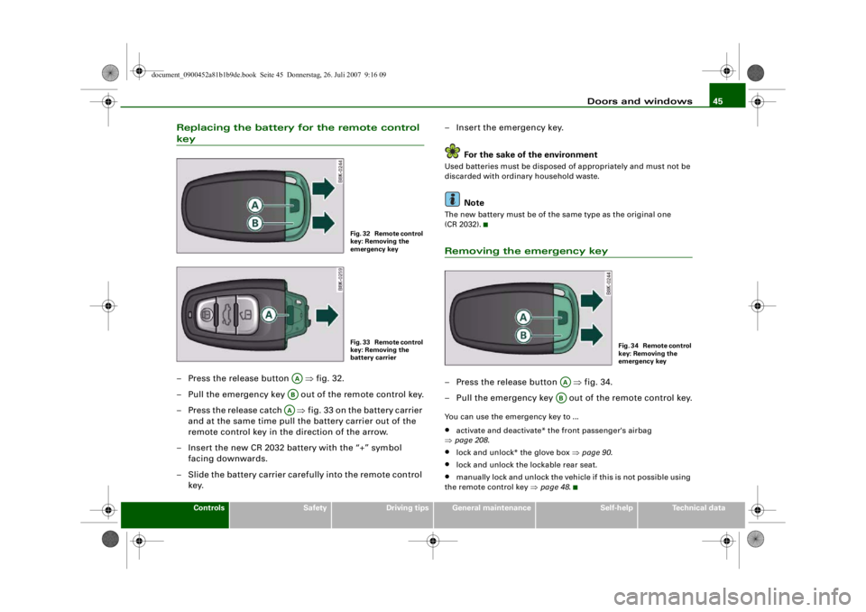
Replacing the battery for the remote control key– Press the release button ⇒fig. 32.
– Pull the emergency key out of the remote control key.
– Press the release catch ⇒ fig. 33 on the battery carrier
and at the same time pull the battery carrier out of the
remote control key in the direction of the arrow.
– Insert the new CR 2032 battery with the “+” symbol facing downwards.
– Slide the battery carrier carefully into the remote control key. – Insert the emergency key.
For the sake of the environment
Used batteries must be disposed of appropriately and must not be
discarded with ordinary household waste.
Note
The new battery must be of the same type as the original one
(CR 2032).Removing the emergency key– Press the release button ⇒fig. 34.
– Pull the emergency key out of the remote control key.You can use the emergency key to ...•
activate and deactivate* the front passenger's airbag
⇒ page 208 .
•
lock and unlock* the glove box ⇒page 90 .
•
lock and unlock the lockable rear seat.
•
manually lock and unlock the vehicle if this is not possible using
the remote control key ⇒page 48 .
Fig. 32 Remote control
key: Removing the
emergency keyFig. 33 Remote control
key: Removing the
battery carrier
AAABAA
F i g . 3 4 R e m o t e c o n t r o l
key: Removing the
emergency key
AAAB
document_0900452a81b1b9de.book Seite 45 Donnerstag, 26. Juli 2007 9:16 09
--4 -
-T
[I]
•
-+
•
+-
Page 48 of 342
Doors and windows
46Emergency release for ignition key
In the event of a malfunction in the vehicle's electrical
system, it may no longer be possible to remove the igni-
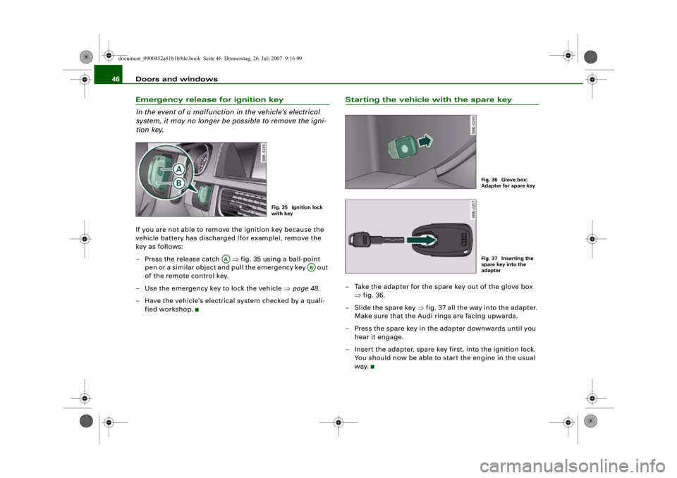
tion key.If you are not able to remove the ignition key because the
vehicle battery has discharged (for example), remove the
key as follows:
– Press the release catch ⇒fig. 35 using a ball-point
pen or a similar object and pull the emergency key out
of the remote control key.
– Use the emergency key to lock the vehicle ⇒page 48 .
– Have the vehicle's electrical system checked by a quali- fied workshop.
Starting the vehicle with the spare key– Take the adapter for the spare key out of the glove box ⇒fig. 36.
– Slide the spare key ⇒fig. 37 all the way into the adapter.
Make sure that the Audi rings are facing upwards.
– Press the spare key in the adapter downwards until you hear it engage.
– Insert the adapter, spare key first, into the ignition lock. You should now be able to start the engine in the usual
way.
Fig. 35 Ignition lock
with key
AA
AB
Fig. 36 Glove box:
Adapter for spare keyFig. 37 Inserting the
spare key into the
adapter
document_0900452a81b1b9de.book Seite 46 Donnerstag, 26. Juli 2007 9:16 09
--4 -
-T
-+ +-
•
•
Page 92 of 342
Seats and storage
90•
If the power drawn by the connected appliances is above 150 W,
the inverter in the socket will get warm. The inverter will trip out if
the temperature exceeds a certain limit. The inverter can trip out on
hot days even when an appliance with a suitable power rating is
used. The inverter will switch on again automatically after it has
cooled down. Appliances whic h are already connected and
switched on will be activated again automatically ⇒ .
•
Do not connect lamps which contain a neon tube. For technical
reasons, this may damage the lamp.
•
Do not connect 115 Volt appliances to the 230 Volt Euro socket.
This may cause irreparable damage to the appliance. Check the type
plate on the appliance if you are unsure of the voltage rating.
•
With some power supplies (e.g. on laptop computers), the inte-
grated surge suppressor prevents the equipment from being
switched on because the starting current is too high. If this
happens, please disconnect the power supply unit from the load
and wait for about 10 seconds before re-connecting.Note
•
Unshielded equipment can cause interference on the radio, TV
and vehicle's electrical system.
•
The Euro socket has an integrated child safety device. There is no
power at the socket until the Euro connector is fully inserted.
•
Some appliances may not function normally due to the lower
power rating (wattage).
•
The socket can be operated with 115 Volt power supplies, as is
the case in certain countries. In this case, a different type of inverter
must be installed in the vehicle. Retrofit kits are available from your
Audi dealer. Do not connect 115 Volt appliances to the 230 Volt Euro
socket.
•
Interference can occur on the radio's AM waveband if electrical
appliances are used near the rear window aerial.
Storage compartmentsOverview
There are several storage compartments at various points
in the vehicle.Glove box
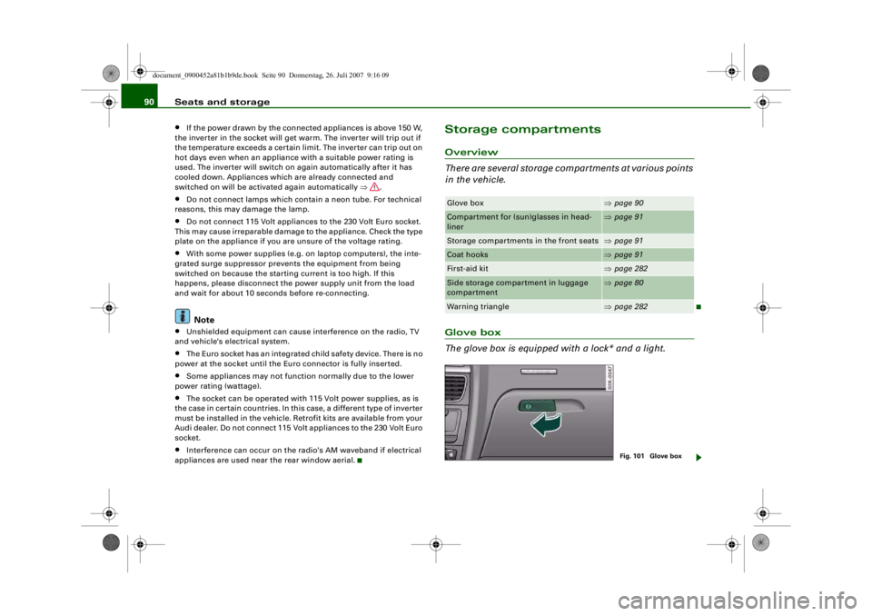
The glove box is equipped with a lock* and a light.Glove box
⇒page 90
Compartment for (sun)glasses in head-
liner
⇒page 91
Storage compartments in the front seats
⇒page 91
Coat hooks
⇒page 91
First-aid kit
⇒page 282
Side storage compartment in luggage
compartment
⇒page 80
Warning triangle
⇒page 282
Fig. 101 Glove box
document_0900452a81b1b9de.book Seite 90 Donnerstag, 26. Juli 2007 9:16 09
--4 -
-T
-+
rn
•
Page 93 of 342
Seats and storage91
Controls
Safety
Driving tips
General maintenance
Self-help
Technical data
Opening glove box
– Pull the catch on the lid in the direction indicated (arrow)
⇒page 90, fig. 101 and open the lid.
Closing glove box
– Close the lid and push it in until it engages.The glove box lid has separate holders for a pen and a note pad.
On the right-hand side of the glove box there is a holder with a key
shell. In order to start the engine with the spare key, it has to be
clipped into this shell.
WARNING
To avoid the risk of injuries, al ways keep the glove box lid closed
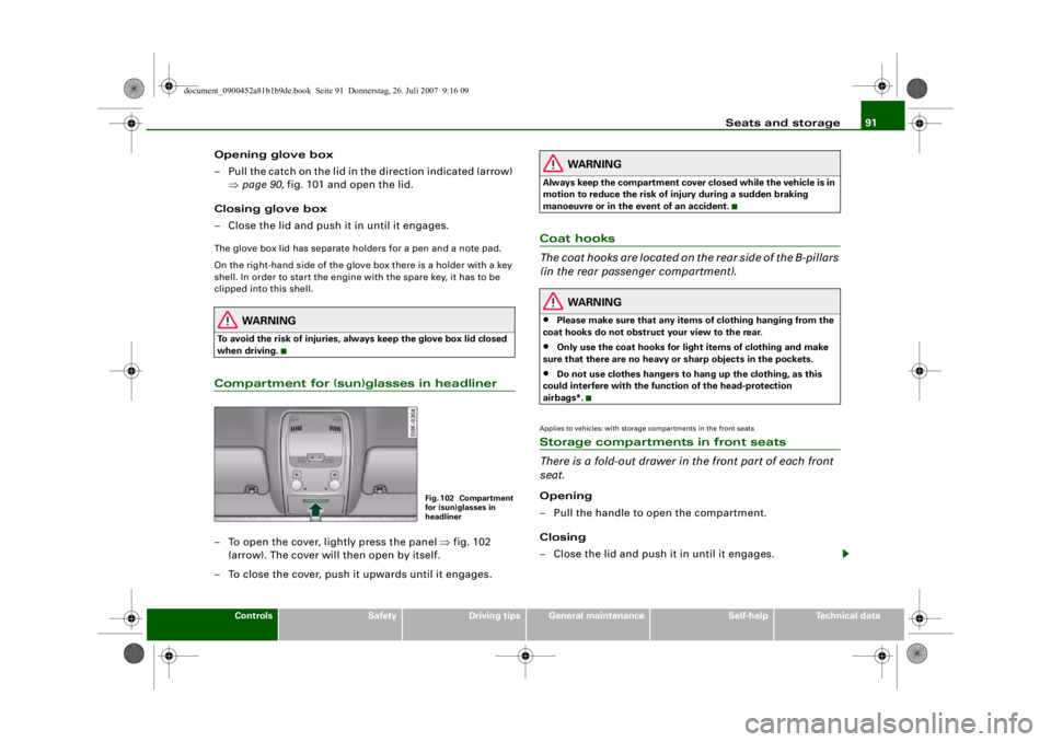
when driving.Compartment for (sun)glasses in headliner– To open the cover, lightly press the panel ⇒fig. 102
(arrow). The cover will then open by itself.
– To close the cover, push it upwards until it engages.
WARNING
Always keep the compartment cover closed while the vehicle is in
motion to reduce the risk of injury during a sudden braking
manoeuvre or in the event of an accident.Coat hooks
The coat hooks are located on the rear side of the B-pillars
(in the rear passenger compartment).
WARNING
•
Please make sure that any items of clothing hanging from the
coat hooks do not obstruct your view to the rear.
•
Only use the coat hooks for light items of clothing and make
sure that there are no heavy or sharp objects in the pockets.
•
Do not use clothes hangers to ha ng up the clothing, as this
could interfere with the function of the head-protection
airbags*.
Applies to vehicles: with storage compartments in the front seatsStorage compartments in front seats
There is a fold-out drawer in the front part of each front
seat.Opening
– Pull the handle to open the compartment.
Closing
– Close the lid and push it in until it engages.
Fig. 102 Compartment
for (sun)glasses in
headliner
document_0900452a81b1b9de.book Seite 91 Donnerstag, 26. Juli 2007 9:16 09
--4 -
-T
•
-+
Ir-& -.
--1
•
+-
Page 205 of 342
Airbag system203
Controls
Safety
Driving tips
General maintenance
Self-help
Technical data
Front airbagsDescription of front airbags
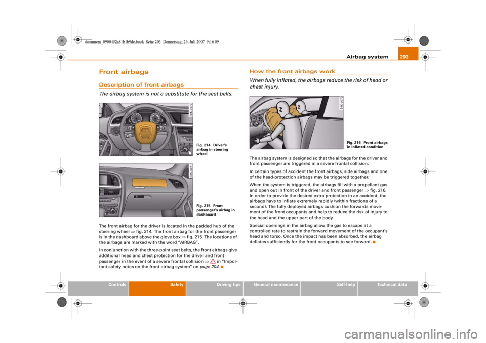
The airbag system is not a substitute for the seat belts.The front airbag for the driver is located in the padded hub of the
steering wheel ⇒fig. 214. The front airbag for the front passenger
is in the dashboard above the glove box ⇒fig. 215. The locations of
the airbags are marked with the word “AIRBAG”.
In conjunction with the three-point seat belts, the front airbags give
additional head and chest protection for the driver and front
passenger in the event of a severe frontal collision ⇒ in “Impor-
tant safety notes on the front airbag system” on page 204.
How the front airbags work
When fully inflated, the airbags reduce the risk of head or
chest injury.The airbag system is designed so that the airbags for the driver and
front passenger are triggered in a severe frontal collision.
In certain types of accident the front airbags, side airbags and one
of the head-protection airbags may be triggered together.
When the system is triggered, the airbags fill with a propellant gas
and open out in front of the driver and front passenger ⇒fig. 216.
In order to provide the desired extra protection in an accident, the
airbags have to inflate extremely rapidly (within fractions of a
second). The fully deployed airbags cushion the forwards move-
ment of the front occupants and help to reduce the risk of injury to
the head and the upper part of the body.
Special openings in the airbag allow the gas to escape at a
controlled rate to restrain the fo rward movement of the occupant's
head and torso. Once the impact has been absorbed, the airbag
deflates sufficiently for the front occupants to see forward.
Fig. 214 Driver's
airbag in steering
wheelFig. 215 Front
passenger's airbag in
dashboard
Fig. 216 Front airbags
in inflated condition
document_0900452a81b1b9de.book Seite 203 Donnerstag, 26. Juli 2007 9:16 09
--4 -
-T
-+ +-
•
•
Page 210 of 342
Airbag system
208second). The airbag releases a fine dust when it inflates. This is quite
normal and does not mean there is a fire in the vehicle.Important safety notes on the head-protection airbags
There are a number of safety points concerning the airbag
system which you should remember. This will help to
reduce the risk of injury in an accident.
WARNING
•
It is important to ensure that the area around the openings for
the head-protection airbags remains unobstructed at all times, so
that the airbags can in flate properly if needed.
•
The built-in coat hooks should only be used for lightweight
clothing. Do not leave any heavy or sharp-edged objects in the
pockets. When using the coat hooks, do not hang the clothes on
coat hangers.
•
The space between the passenge rs and the head-protection
airbags must never be occupied by children, other passengers or
pets. Passengers should never lean out or put a hand or arm out of
the window while the vehicle is in motion.
•
Do not move the sun visors out to cover the side windows if
there is anything attached to th em (such as pens or a remote
control for the garage door). These objects could cause injury if the
head-protection airbag is triggered.
•
The sensors for the airbags are lo cated in the front doors. You
must therefore not make any modifications to the doors or door
trim (e.g. retrofitting loudspeakers ), as this could impair the func-
tion of the side airbags. Any dama ge to the front doors could lead
to faults in the system. Repairs or any other work on the front
doors must therefore always be carried out by a qualified work-
shop.
•
Where sun blinds are fitted on th e rear doors, these must not
obstruct or impair th e airbags in any way.
•
If unsuitable accessories are installed near the head-protection
airbag, the protection afforded by the airbag can be seriously
impaired if the system is trigge red. When the head-protection
airbag opens, parts of these acce ssories could be thrown into the
vehicle and injure passengers ⇒page 277 .
•
Any work involving the head-protection airbags, or removal
and installation of the airbag components for other repairs (such
as repairs to the roof liner), mu st always be performed by a quali-
fied workshop. Otherwise the airbag system may fail to work
properly.
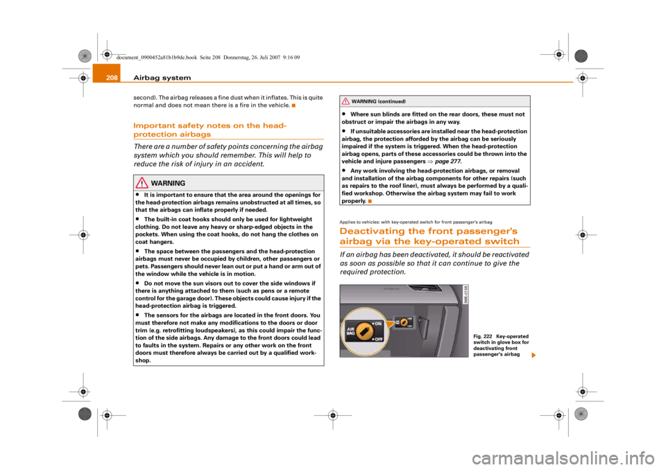
Applies to vehicles: with key-operated switch for front passenger's airbagDeactivating the front passenger's airbag via the key-operated switchIf an airbag has been deactivated, it should be reactivated
as soon as possible so that it can continue to give the
required protection.
WARNING (continued)
Fig. 222 Key-operated
switch in glove box for
deactivating front
passenger's airbag
document_0900452a81b1b9de.book Seite 208 Donnerstag, 26. Juli 2007 9:16 09
--4 -
-T
•
•
-+ +-
Page 211 of 342
Airbag system209
Controls
Safety
Driving tips
General maintenance
Self-help
Technical data
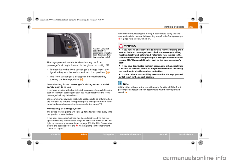
The key-operated switch for deactivating the front
passenger's airbag is located in the glove box ⇒fig. 222.
– To deactivate the front passenger's airbag, insert the ignition key into the switch and turn it to position .
– The front passenger's airbag can be reactivated by turning the key to position .Deactivating front passenger 's airbag when a child
safety seat is in use
If you have no alternative but to i nstall a rearward-facing child safety
seat on the front passenger's seat you must deactivate the front
passenger's airbag beforehand.
We recommend, however, that child seats should be only fitted on
the rear seat so that the front passenger's airbag can remain func-
tional and provide protection in an accident ⇒page 210 .
Monitoring of airbag system
The airbag warning lamp will light up for a few seconds every time
the ignition is switched on.
If the front passenger's airbag ha s been deactivated via the key-
operated switch, the indicator lamp “PASSENGER AIRBAG OFF” will
light up constantly as a reminder ⇒page 209, fig. 223. Please refer
also to the description of the
warning lamp in the instrument
cluster ⇒page 17 . When the front passenger's airbag is deactivated using the key-
operated switch, the seat belt warning lamp for the front passenger
⇒ page 18 is also switched off.
WARNING
•
If you have no alternative but to install a rearward-facing child
seat on the front passenger's se at, the front passenger's airbag
must be deactivated beforehand. Po tentially fatal injuries to the
child can result if the front passenger's airbag is not deactivated!
⇒ page 211, “Using a child safety seat on the front passenger's
seat”
•
If you have deactivated the fron t passenger's airbag, reactivate
it as soon as the chil d seat is no longer needed so that the airbag
can continue to give the required protection.
•
It is the driver's responsibility to ensure that the key-operated
switch is set to the correct position.Note
All the other airbags in the car will remain functional if the front
passenger's airbag has been deactivated with the key-operated
switch.
Fig. 223 Lamp indi-
cates that front
passenger's airbag has
been deactivated via
key-operated switch
AOFF
AON
document_0900452a81b1b9de.book Seite 209 Donnerstag, 26. Juli 2007 9:16 09
--4 -
-T
-+
[I]
+-
•
Page 336 of 342
Index
334
Operation . . . . . . . . . . . . . . . . . . . . . . . 121
Parking . . . . . . . . . . . . . . . . . . . . . . . . . 122
Releasing and applying . . . . . . . . . . . 121
Warning lamp . . . . . . . . . . . . . . . . . 19, 20
Electronic differential lock How the system works . . . . . . . . . . . . 222
Warning lamp . . . . . . . . . . . . . . . . . . . . 19
Electronic immobiliser . . . . . . . . . . . . . 14, 43
Electronic stab ilisation program
How the system works . . . . . . . . . . . . 222
Warning lamp . . . . . . . . . . . . . . . . . . . . 17
Emergency braking function . . . . . . . . . . 123
Emergency key . . . . . . . . . . . . . . . . . . . . . . 45
Emergency release Ignition key . . . . . . . . . . . . . . . . . . . . . . 46
Emission control systems Catalytic converter . . . . . . . . . . . . . . . 229
Diesel particulate filter . . . . . . . . . . . . 229
Emissions . . . . . . . . . . . . . . . . . . . . . . . . . 321
Engine compartment Safety notes . . . . . . . . . . . . . . . . . . . . . 255
Engine compartment layout . . . . . . . . . . 256
Engine data See Performance, weights and
dimensions . . . . . . . . . . . . . . . . . . . . 323
Engine hood See Bonnet . . . . . . . . . . . . . . . . . . . . . . 254
Engine management (EPC) warning lamp . . . . . . . . . . . . . . . 16
Engine oil . . . . . . . . . . . . . . . . . . . . . . 34, 257 Checking oil level . . . . . . . . . . . . 258, 259
Consumption . . . . . . . . . . . . . . . . 258, 259
LongLife Service . . . . . . . . . . . . . . . . . 257 Topping up . . . . . . . . . . . . . . . . . . . . . . 259
See also
Performance, weights and
dimensions . . . . . . . . . . . . . . . . . . . . 323
Engine oil capacity See Performance, weights and
dimensions . . . . . . . . . . . . . . . . . . . . 323
Engine oil pressure Warning lamp . . . . . . . . . . . . . . . . . . . . 33
Engine oil sensor Malfunction . . . . . . . . . . . . . . . . . . . . . . 38
Environmental compatibility . . . . . . . . . . 231
Environmental tips Filling the tank . . . . . . . . . . . . . . . . . . . 252
Heated rear window . . . . . . . . . . . 98, 106
Leaks . . . . . . . . . . . . . . . . . . . . . . . . . . . 255
Roof carrier . . . . . . . . . . . . . . . . . . . . . . 84
EPC See Engine management . . . . . . . . . . . 16
ESP See Electronic stabilisation program . 17
Ethanol fuel . . . . . . . . . . . . . . . . . . . . . . . . 251
Exterior mirrors . . . . . . . . . . . . . . . . . . . . . . 70
FFastening rings . . . . . . . . . . . . . . . . . . 79, 193
Filling the tank . . . . . . . . . . . . . . . . . . . . . 252 Releasing the tank flap manually . . . 253
Fire extinguisher . . . . . . . . . . . . . . . . . . . . 283
First-aid kit . . . . . . . . . . . . . . . . . . . . . . . . . 282
Floor mats . . . . . . . . . . . . . . . . . . . . . 191, 192
Fog lights . . . . . . . . . . . . . . . . . . . . . . . . . . . 58
Four-wheel drive . . . . . . . . . . . . . . . . . . . . 226 Front passenger
See Sitting position . . . . . . . . . . . . . . . 189
Fuel Biodiesel . . . . . . . . . . . . . . . . . . . . . . . . 251
Capacity . . . . . . . . . . . . . . . . . . . . . . . . 321
Consumption . . . . . . . . . . . . . . . . . . . . 321
Current fuel consumption . . . . . . . . . . 25
Diesel . . . . . . . . . . . . . . . . . . . . . . . . . . 251
Ethanol . . . . . . . . . . . . . . . . . . . . . . . . . 251
Fuel level low . . . . . . . . . . . . . . . . . . . . . 37
Petrol . . . . . . . . . . . . . . . . . . . . . . . . . . 251
Saving fuel . . . . . . . . . . . . . . . . . . . . . . 229
Fuel consumption . . . . . . . . . . . . . . . . . . . 321
Fuel range . . . . . . . . . . . . . . . . . . . . . . . . . . 25
Fuel tank flap . . . . . . . . . . . . . . . . . . . . . . . 252
Fuse, changing . . . . . . . . . . . . . . . . . . . . . 300
GGarage door opener . . . . . . . . . . . . . . . . . 179
Gear-change indicator . . . . . . . . . . . . . . . . 22
Generator See Alternator . . . . . . . . . . . . . . . . . . . . 32
Glove box . . . . . . . . . . . . . . . . . . . . . . . . . . . 90
Glow plug system Indicator lamp . . . . . . . . . . . . . . . . . . . . 16HHandbrakeSee Electro-mechanical parking brake . . .
121
document_0900452a81b1b9de.book Seite 334 Donnerstag, 26. Juli 2007 9:16 09
--4 -
-T
-+ +-