start stop button AUDI S4 2013 User Guide
[x] Cancel search | Manufacturer: AUDI, Model Year: 2013, Model line: S4, Model: AUDI S4 2013Pages: 302, PDF Size: 75.61 MB
Page 91 of 302
.. Select: ICARlfunction button> Car sys
t e m s*
control button > Drive r as sist >
Spe ed w arning.
Warning th resho ld 2 can be set in the speed
range starting from 20 mph to 150 mph (30
km/h to 240 km/h). Settings can each be ad
justed in intervals of 6 mph (10 km/h).
Cruise control
Switching on
The cruise control system makes it possible to
drive at a constant speed starting at 20 mph
(30 km/h).
®
f
®t
0
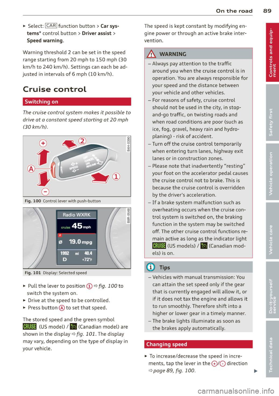
Fig. 100 Control lever wi th push -button
Fi g. 101 Disp lay: Se lected speed
.. Pull the lever to position (D ¢ fig. 100 to
switch the system on.
.. Drive at the speed to be controlled .
.. Press button @to set that speed.
The stored speed and the green symbol
[ij;jl)~i~ (US model)/ .. (Canadian model) are
shown in the display
¢fig. 101. The display
may vary, depending on the type of display in
your veh icle.
On th e road 89
The speed is kept constant by modifying en
gine power or through an active brake inter
vention.
_& WARNING
- Always pay attention to the traffic
around you when the cruise control is in
operation. You are always responsible for
your speed and the distance between
your veh icle and other vehicles.
- For reasons of safety, cru ise control
should not be used in the city, in stop
a nd-go traffic, on twisting roads and
when road cond itions are poor (such as
ice, fog, gravel, heavy rain and hydro
p lan ing) -risk of accident .
- Turn
off the cruise control temporar ily
when enter ing turn la nes, highway exit
lanes or in construction zones .
- Please no te that inadverten tly "resting"
your foot on the accelerator pedal causes
the cruise contro l not to brake. This is
because the cruise control is overridden
by the driver's acceleration.
- If a brake system malfunction suc h as
overheating occurs when the cruise con
trol system is switched on, the braking
function in the system may be switched
off. The other cruise contro l functions re
main active as long as the indicator l igh t
lijj(l)~i~ (US mode ls)/ Iii (Canad ian mod
e ls) is on.
@ Tips
- Veh icles with ma nual transmiss ion: You
can attain the set speed only if the gear
that is currently engaged will a llow it, or
if it does not tax the engine a nd allows i t
t o r un smoothly. Therefore shift in to a
higher or lower gear in a time ly manner.
- The bra ke ligh ts ill umina te as soon as
the brakes app ly au tomatically.
Changing speed
.. To increase/decrease the speed in incre
ments, tap the lever in the
010 direction
¢ page 89, fig. 100. Ill>
Page 96 of 302
94 Transmission Starting the engine
.. The selec to r l eve r must be in P or N.
Starting off
.. Press and hold the brake pedal.
.. Press and hold the release button in these
lector lever handle, select t he des ired selec
tor lever position such as D/S and release
the b utton .
.. Wait briefly until the transmission has shift
ed (you will feel a slight movement) .
.. Remove your foot from the brake pedal and
acce lerate.
Stopping temporarily
.. Keep the vehicle stationary using the b rak
ing peda l, for examp le at traffic lights .
.. Do not press the accelerator pedal when do
ing this.
.. To prevent the vehicle from rolling when
you start dr iving, set the parking brake
when stopping on steep inclines ¢&_ .
.. The parking brake will release automatically
and the vehicle w ill start moving once you
press the accelerator peda l.
Stopping/parking
If the selector lever is not in the P position
when you open the dr iver's door, the vehicle
could roll. The message
Transmission: Car
may roll! Shift to park!
appears.
.. Press and hold the brake pedal unt il the ve
hicle has come to a complete stop .
.. Apply the parking brake¢
page 86, Park-
ing .
.. Se lect the P selector lever position ¢ &.-
Stopping on an incline
.. Always press the brake pedal to hold the ve
hicle in place and prevent it from "rolling
back"
¢ &_ . Do not try to prevent the vehi
cle from "rolling back" when a gear is en
gaged by increasing the engine speed ¢Q).
Starting on an incline
.. Activate the parking brake.
.. With the driving gear selected, press the ac
celerator pedal carefully . The parking brake will release automatically if your seat
belt is
fastened .
Under certain circumstances, such as driving
in the mountains, it may be usefu l to switch
temporarily to the manual shift program in or
der to adjust the gears to the driving condi
tions by hand ¢
page 96.
On s lopes, activate the parking brake first and
then move the selector lever to the P position .
This prevents too much stress from being
placed on the locking mechanism .
Vehicles with multitronic transmission: Your
vehicle is equipped with
hill hold assist allow
ing yo u to start while on an incline. The sys
tem is activated when the brake pedal is
pressed down and he ld
for a few seconds . The
brake pressure will hold for
a moment after
the brake pedal loosens to prevent the vehicle
from roll ing backwards w hile starting up .
A WARNING
-The vehicle can also roll when the engine
is stopped.
-Unintended vehicle movement can cause
serious injury.
- Never leave your vehicle with the engine
r un ning while in gear. If you must leave
your veh icle when the engine is running,
activate the parking brake and move the
selector lever to P.
- Power is still transmitted to the wheels
when the engine is runn ing at idle. To
prevent the vehicle from "creeping", you
must keep your foot on the brake when
the engine is running and the selector
lever is in 0/5 or R or "t iptronic" mode is
selected .
- Do not press the accelerator pedal when changing the selector lever position
while the veh icle is stationary and the
engine is running.
- Never shift into R or P while driving.
- Before driving down a steep s lope, re-
duce your speed and shift into a lower
gear with "tiptronic" .
Page 99 of 302
A WARNING 1=
Please note that the drive wheels can spin
if kick-down is used on a smooth slippery
road - there is a risk of skidding.
Launch Control Program
App lies to vehicles: with S tronic
The Launch Control Program provides the
best acceleration possible when starting from
a stop .
Requirement : The engine must be at operat
ing temperature and the steering wheel must
not be turned .
~ Press the l.e OFFI button ¢ page 187 or
r:::> page 188 while the engine is running.
The
fsl indicator light illuminates in the in
strument cluster and
Tra ction con trol
( ASR ): Off. W arning! Re stri cted stabil ity
appears in the dr iver information system
display .
~ Move the selec to r l ever to the D/S position
or se lect the
d y nami c driving mode in drive
select*
r:::> page 114.
~ Press the brake peda l strong ly wit h your left
foot and hold it down for at least 1 second.
~ At the same time, press the accelerator
pedal down completely with your right foot
until the engine reaches and maintains a
high RPM .
~ Remove your foot from the brake peda l
within 5 seconds
r:::> .&, .
A WARNING
-Always adapt you r driving to the traffic
flow.
- Only use the Launch Control Program
when road and traffic conditions allow it
and other drivers will not be endangered
or annoyed by you r driv ing and the vehi
cle's acce leration.
- Please note that the driving wheels can
spin and the vehicle can break away
when ASR is switched off, especially
when the road is slippery.
-
Tran sm iss ion 97
-Once you have accelerated, you shou ld
sw itch the ASR back on by pressing the
l.e O FFI button.
(D Tips
- The transmission temperature may in
crease s ignificantly after using the
Launch Control Program. If that hap-
pens, the program may not be availab le
for a few m inutes. It will be ava ilable
again after a cool-down per iod .
- When accelerating using the Launch
Cont ro l program, a ll vehicle parts are
subject to heavy loads. This can result in
increased wear .
Transmission malfunction
Applies to vehicles: with multitro nic/S tronic/t iptronic
[O] Transmis sion: Pr ess brake p edal and se·
Leet gear again .
Press the brake peda l and select the desired
selector lever position again. You ca n the n
continue driving.
[O] Trans mission overhe ating: Pl ease drive
conservatively .
The transmiss ion temperature has increased
s ignificantly due to the sporty d riving manner .
D rive in a less sporty ma nner until the tem
perature returns to the normal range and the
indicato r light switc hes of.
[O] Tran smission malfunction: You can con
tinue driv ing
There is a system malfunction in the transmis
sion. You may cont inue driving. Drive to your
authorized Aud i dea ler or qualified repa ir fa
c ility soo n to have the malfunction corrected .
[O] Transm ission malfunction : Lim ited dr iv·
ing functionality
There is a system malfunction in the t ransmis
s ion . The transm ission is switching to emer
gency mode . This mode on ly shifts into cer-
ta in gears or will no longer shift at all. The en
gine may sta ll. Dr ive to your authorized Audi ..,.
Page 116 of 302
114 Audi drive select
-For vehicles with an automatic transmis
sion, selecting the
Dynamic mode re
su lts in sporty shifting characteristics .
The S gear position engages automati
cally.
- In vehicles that have dynamic steering*,
operating noise is heard when starting or
stopping the eng ine . This does not ind i
cate a problem .
Selecting the driving mode
Applies to vehicles: with Audi drive select
You con choose between Comfort, Auto, Dy·
namic
and Individual * modes.
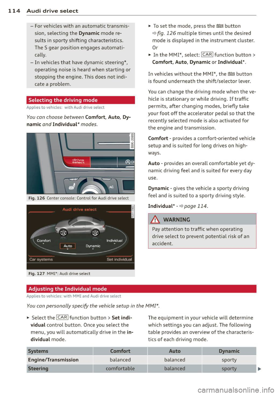
Fig. 126 Center console: Control for Au di dri ve select
Fig. 127 MMI•: Aud i drive select
Adjusting the Individual mode
Applies to vehicl es: with MMI and Aud i drive select
.,. To set the mode, press the f:l:-.i button
~ fig. 126 multiple times until the desired
mode is displayed in the instrument cluster .
Or
.,. In the MMI*, select: ICARlfunction button>
Comfort, Auto, Dynamic or Individual *.
In vehicles without the MMI*, the~:/;-~ button
is found underneath the shift/selector lever.
You can change the driving mode when the ve
hicle is stationary or wh ile driving . If traffic
permits, after changing modes, br iefly take
your foot off the accelerator pedal so that the recently selected mode is also activated for
the engine and transm ission .
Comfort -provides a comfort-oriented vehicle
setup and is suited for long drives on h igh
ways .
Auto -provides an overall comfortable yet dy
namic driving feel and is suited for every day
use.
Dynamic -gives the vehicle a sporty driving
feel and is suited to a sporty driving style.
Individual * -¢page 114.
& WARNING
Pay atte ntion to traffic when operating
drive select to prevent potential risk of an
accident .
You con personally specify the vehicle setup in the MMI* .
.,. Se lect the ICAR I function butto n > Set indi ·
vidual
control but ton. Once you select th e
menu, you will automatically drive in the
in·
dividual
mode.
Systems Comfort
Engine/Transmi ssion
balanced
Steering comfortable T
he equipment in your vehicle will determine
wh ich sett ings you can adjust. The following
table provides an overview of the characteris
tics of each driving mode .
Auto Dynamic
balanced sporty
balanced sporty
Page 125 of 302

Homelink®
Universal remote
control
Description
Applies to vehicles: with Home link
The HomeLink universal remote control con
be programmed with the remote control for
devices that ore already present.
With Home Link, you can control devices such
as the garage door, secu rity systems, ho use
lights , etc. comfortably from the inside of you
vehicle .
H omelink makes it poss ible for you to rep lace
three different remote controls from dev ices
i n your home with one universal remo te. Th is
featu re works for most garage door and exte
rior door motor signals. Programming the in
d ividual remote control for your remote con
trol takes p lace near the center of the radiator
grille. There is a control module attached at
this location .
A one-t ime programm ing of the sensor must
be performed before you are able to use sys
tems with Homelink. If the system does not activate after performing the one-t ime pro
gramming, check whether the system uses a rolling code ¢
page 126 for vehicles without
the MMI*.
,& WARNING
-
-Never use the Homelink ® transmi tter
with any garage door opener that does have not the sa fety stop and reverse fea
ture as requ ired by federa l safety stand
ards. Th is includes any garage door open
er mode l manufactured before April 1,
1982.
- A garage door opener which cannot de
tect an object, signaling the door to stop
and reverse does not meet current feder
al safety standards . Us ing
a garage door
opener without these features increases
risk of serious injury or death.
Homelink ® 123
-For safety reasons never re lease the
parking brake or start the eng ine while
anyone is standing in front of the vehicle .
- A garage door or an estate gate may
sometimes be set in motion when the Homelink ® remote control is being pro
grammed. If the device is repeatedly ac
tivated, th is can overstrain motor and
damage its e lectrical components -an
overheated mo to r i s
a fire hazard!
- To avoid possib le injuries or property
damage, please always make abso lutely
certain that no person s or objects are lo
cated in the range of motion of any
equ ipment being operated .
(D Tips
-If you would like more information on
Homelink ®, where to purchase the
Home link ® compatib le products, or
would like to purchase the Homelink ®
Home Lighting Package, please ca ll toll
free: l-800-355-3515.
- For Declaration of Compliance to United
States FCC and Industry Canada reg ula
tions¢
page 283.
- For security reasons, we recommend that
you clear the programmed b uttons be
fore selling the veh icle.
Operation
App lies to vehicles : with Homeli nk
~~''' r ·O : O ·) 1111
~
®
Fig . 1 36 Head li ner: controls
Req uirement : The buttons must be program-
med
<:!)page 124 or ¢page 125. ..,_
Page 127 of 302
Programming the transmitter (version
B)
Applies to vehicles: with Horne link
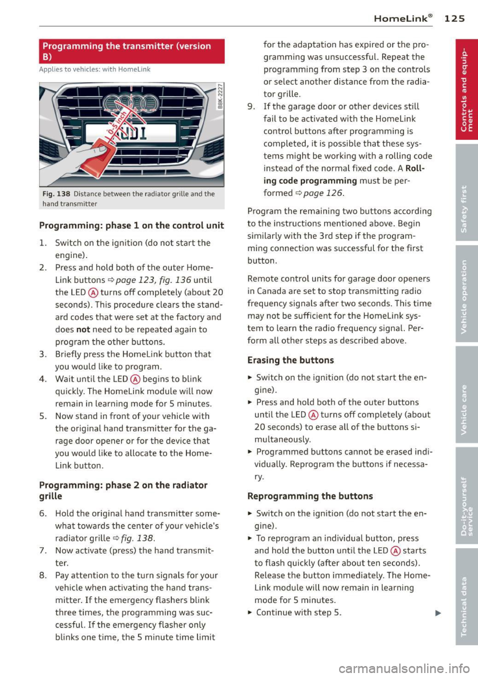
Fig. 1 38 D istance between t he rad ia tor grill e and t he
hand transmitte r
Programming: phase 1 on the control unit
1. Sw itch on the ig nit io n (d o n ot start the
e ngine ).
2. P ress and hold bot h of the outer Home
Link buttons
r=> page 123, fig. 136 unt il
the LED @ turns off completely (about
20
seconds). Th is procedure clears the stand
ard codes that were set at the factory and
does
not need to be repeated agai n to
p rog ram th e othe r buttons.
3. Briefly press the Homelink button that
you would like to prog ram .
4 . Wai t until the LED@ beg ins to blink
q ui ckly. The Home Lin k modu le wi ll now
remai n in learning mode for
5 minutes .
5. Now stand in front of your vehicle with
the original hand transmitter for the ga rage door opener o r for the device that
you would like to allocate to the Home
Link button.
Programming: pha se 2 on the radiator
grille
6 . Hold the o rig inal hand transmitter some
what towa rds the center o f you r vehicle 's
radiato r gr ille
r=> fig . 138 .
7. Now activate (p ress) t he hand transmit
ter.
8 . Pay a ttention to the t urn sign als for yo ur
vehicle when activating the ha nd trans
mitter . If t he emergency flashers b link
three times, the programming was suc
cessful. If the emergency flasher only
bli nks one time, the 5 minute t ime limit
Homelink ® 125
for the adaptat ion has expired or the pro
gram ming was unsuccessful. Repeat the
programming from step 3 on the controls
o r se lect another distance from the radia
tor grille.
9. If the garage door or other devices sti ll
fail to be activated w it h the Homelink
control buttons after p rogramming is
comple ted, it is possib le tha t these sys
tems might be wor king with a roll ing code
ins tead of the normal fixed code .
A Roll
ing code programming must be per
formed
r=> page 126 .
Program the rema ining tw o b uttons a ccord ing
to the instructions mentioned above . Beg in
similar ly w ith the 3rd step if the program
m ing connection was successful for t he first
button .
Remote con trol units fo r garage door opene rs
in Canada are set to stop transmitting radio
frequency signa ls after two seconds . This time
may not be suffic ient for the Homelink sys
tem to learn the radio frequency signa l. Per
form all other steps as described above.
Erasing the buttons
.,. Switch o n the ignition (do not start the en
gi ne).
.,. Press and hold both of the outer buttons
until the LED @ turns off completely (about
20 seconds) to erase all of the buttons si
m ultaneously .
.,. Programmed buttons cannot be erased ind i
vidua lly. Reprogram the buttons if necessa
ry .
Reprogramming the buttons
.,. Switch on the ignition (do not start the en
gine) .
.,. To reprogram an individua l butto n, press
and hold the button unt il the LED @ starts
to f lash quickly (after abo ut ten seconds) .
Release t he bu tton imme dia tely. The Home
L ink module will now remain in learning
mo de for 5 minutes.
.,. Continue with step 5.
Page 190 of 302
188 Intelligent technology
allroad: Switching on /off
ESC turns on automatically when you start
the engine .
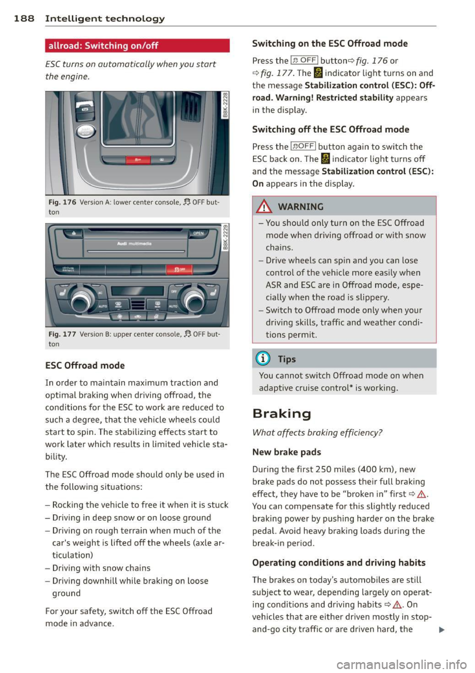
Fig. 176 Version A: lower ce nter console,~ OFF but
to n
...... [ I I n-I _,,. .,., -------' -"~ __..,
Fig. 177 Versio n B: upper ce nter conso le,~ OFF but
to n
ESC Offroad mode
In order to maintain maximum traction and
optima l brak ing when driving offroad , the
conditions for the ESC to work are reduced to
such a degree, tha t the vehicle whee ls co uld
start to spin . The stabilizing effects start to
work later wh ich results in limited vehicle sta
b ili ty.
The ESC Offroad mode should on ly be used in
the following situations:
- Rocking the vehicle to free it when it is stuck
- Driving in deep snow or on loose ground
- Driving on rough terra in when much of the
car's weight is lifted off the wheels (axle ar
t icu lation)
- Driving with snow cha ins
- Driving downhill while braking on loose
ground
F or your safety, switch off the ESC Offroad
mode in advance.
Switching on th e ES C Offroad mode
Press the In OF FI button ¢ fig. 176 or
¢ fig. 177 . The I indicator light turns on and
the message
St abilization cont ro l ( ES C): Off
ro ad. Wa rning! Rest ricted stability
appears
in the disp lay.
Swit ching off th e ESC Offroad mode
Press the !.$ O FF I button again to sw itch the
ESC back on . The
IJ indicator light turns off
and the message
Stabil ization contro l (ESC ):
On
appears in the display.
_& WARNING
- You shou ld only turn on the ESC Offroad
mode when driving offroad or with snow
chains.
- Drive whee ls can sp in and you can lose
control of the vehicle more easi ly when
ASR and ESC are in Offroad mode, espe
cially whe n the road is slippery.
- Switch to Offroad mode only whe n your
driving skills, traff ic and weather condi
tions permit .
(D Tips
You cannot sw itch Offroad mode on when
adaptive cruise control* is working.
Braking
What affects braking efficiency?
New brake pad s
During the first 250 mi les (400 km), new
brake pads do not possess the ir full brak ing
effect, they have to be "broken in" first¢ .&,.
You can compensate for this slightly reduced
braking power by p ushing harde r on the brake
pedal. Avoid heavy brak ing loads dur ing the
break-in pe riod.
Oper ating cond ition s and driving habit s
The brakes on today's automobiles are still
subject to wear, depending largely on operat
ing co nd it ions and driving hab its
¢ .&, . On
vehicles that are either driven most ly in stop-
and-go city traff ic or are dr iven hard, the
lilJ,,
Page 255 of 302

Tire pressure monitoring system
UJ General notes
Applies to vehicles: with tire pressure monito ring system
Each t ire, i ncluding the spare (if provi ded),
should be chec ked month ly w hen cold and in
flated to the inflation pressure recommended by the vehicle manufacture r o n the vehicle
placar d or tire infla tion pressure label. (If your
veh icle has t ires of a diff erent siz e than the
size ind icat ed on the vehicle p lacard or tir e in
flation pressure label, you should deter mine
the proper tire inflation pressure for those
tires).
As an added safety feature, your vehicle has been equipped with a tire pressure monitor ing
system (TPMS) that illuminates a low tire
pr essu re tellta le when one or mo re of your
tires is significantly under -inflated . Accord ing
l y, when the low tire p ress ure telltale illumi
nates, you should stop and check your tires as
soon as possible, and inflate them to the
proper pressure. Driv ing on a signif icantly un
der-inflated tire causes the tire to overheat
and can lead to tire failure. Under -inflation al
so reduces fuel efficiency and tire t read life,
and may affect the ve hicle's handling and
stopping ab ility.
Please note that the TPMS is not a subst itute
for p roper t ire mainte nance , and it is the dr iv
e r's responsib ility to ma inta in cor re ct t ire
p ress ure, even if under- infla tion has no t
reached the leve l to trigger ill umin ation of the
TPMS low tire pressure telltale.
Your veh icle has also bee n equ ipped with a
TPMS malfunc tion indica to r to indica te when
the system is not opera ting properly. The
TPMS mal function indicato r is combined wi th
the low tire press ure tellta le . When the sys
tem detects a malf unct ion, the te lltale will
flash for approximately one minute and then remain cont inuo usly illuminated. This se
quence will continue upon subsequent vehicle
start-ups as long as the ma lf u nction ex ists .
Tire s an d wheel s 253
When the malfunction indicator is illum inat
ed , the system may not be ab le to detect or
s ignal low tire pressure as intended . TPMS
malfunctions may occur for a var iety of rea
sons, including the insta llation of replace
ment or alternate tires or wheels on the vehi
cle that p revent the TPMS from functioning
proper ly. Always check the TPMS malfunction
te lltale after rep laci ng one or more tires o r
whee ls on you r vehicle to e nsur e th at the re
placement or alterna te t ires and wheels a llow
the TPMS to continue to func tion p roperly.
Tire pressure indicator appears
Applies to vehicles: with tire pressure monitoring system
The tire pressure indica tor in the instrument
cluster informs you if the tire pressure is too
Low or if there is a system malfunction.
Fi g. 19 6 Disp lay: un de rin flat io n warni ng
U sing the ABS sensors, the tire pressure mo ni
toring system compares the tire tread c ircum
ference and vib rat ion character istics of the in
dividua l tir es . If the pressure decreases i n one
o r more t ires, this is indicated in the inst ru
ment cluster with a
[ti wa rning symbo l and a
message ¢
fig. 196. Th e d river message in the
display goes o ut afte r 5 seconds . The driver
message can be displayed again by pressing
the
ISE TI button. If on ly one t ire is affected,
the d isplay w ill indicate its position.
T he tire pressure monitoring system m ust be
reset via radio or M MI* each time the pres
sures are ad justed (e.g. when switc hing be
tween part ial and f ull load press ure) o r after
changing or rep lacing a tire on your ve hicle
¢
page 254. T he TPMS indicator o nly mo ni-
tors the t ire p ress ure t hat yo u have p revio usly ..,.
•
•
Page 289 of 302
_______________________________ ___:I~n ~d ~e:.::x 287
Changin g engine oi l
Chass is 225
U ndercoat ing ............ .... .. .. . 208
Checking
Eng ine coolant level ........ . .. .. .. .
226
Checking tire pressure .............. . 241
Ch ild restraints
D anger of usin g child restraints in the
front seat . . . . . . . . . . . . . . . . . . . . . . . .
146
Where can I get additional information
about child restraints and their use? ..
184
Child restraint system anchors . .. ... .. 180
Ch ild safety .. ............. .... .. ... 166
Convertible locking retractor . . . . . . . . . 176
Important safety instructions for using
ch ild safety seats .... ... .. .. .. .. .. .
169
Impo rtant th ings to know when driv in g
wi th children ............ .... .. ...
166
Insta lling a chi ld res traint using the
L A TCH system ............ .. .. .. .. .
18 1
Mounting and releasing the ancho rage
hook .... .. .. ............. .. .. ...
18 1
Tether anchors . . . . . . . . . . . . . . . . . . . . 182
Tether straps . . . . . . . . . . . . . . . . . . . . . 182
Child safety loc ks
Power windows .......... .. .. .. ....
42
Rear doors ... ........... .. .. ...... 42
Child safety seats .......... .... .. .. . 172
Booster seats ................ .. .. . 17 4
Convertible child seats .... .. .. .. .. .
173
Convertible locking retractor .. .. .. .. . 176
Danger of using child restra ints in the
front seat . . . . . . . . . . . . . . . . . . . . . . . .
146
How do I properly install a child safety
seat in my vehicle? ........ .. .. .. .. .
169
Infant seats . . . . . . . . . . . . . . . . . . . . . . 172
Installing ............ ...... .... .. 176
LATC H system ......... ...... .... .. 18 1
Saf ety inst ruc tions ........ .. .. .. .. . 169
Unused safety belts on the rear seat 17 1
Ch ild seats
L ower ancho rages ........... .. ....
18 1
Cigarette lighter . . . . . . . . . . . . . . . . . . . . . 63
Cleaning
Alcantara® (syn thetic suede) .. .. .. .. .
212
En gine compartment .............. . 213
Exhaust tail pipes ............... .. . 209
Fabr ics and fabric coverings ......... 209
Instrument panel ... . .......... .. .. 210
Interior ... .. .. .. .. . .. .......... .. 209
Leather . . . . . . . . . . . . . . . . . . . . . . . . . . 211
Matte finish paint ................. 204
MMI display/controls ... ......... ... 209
Plastic and vinyl .. .. . .. .. .. ... ... .. 206
Plastic parts ..... .. .. .. .. ......... 210
Safety belts ... .. .. . .............. 21 2
Trim strips .. .. .. .... ........... .. 206
Cleaning and protection . .. .......... . 202
Climate controls ..... . .. .......... .. . 76
Climate control system
Au tom atic recir culat ion ......... .. .. .
79
Supplementary heater ............... 79
synchronizing . . . . . . . . . . . . . . . . . . . . . . 79
Clock .. ... ... .. .... .. .. ...... ... .. . 12
Closing
Power w indows ................... .
42
Sliding/tilting sunroof ............... 44
Sunshade ....... .. . .. ......... ... . 44
Closing/opening
at the lock cylinder .. ........... .... .
38
by remote control ............. .. .. . 35
with the centra l locking sw itch ........
36
with the conven ience key . .......... .. 36
Cold tire inflation pressure .......... .. 238
Coming home ... .. .... ........... .. . 48
Compact spare tire .................. 256
also refer to Spare tire ....... ... .. .. 256
Compartments . . . . . . . . . . . . . . . . . . . . . . 66
Compass in the mirror ... ......... ... . 56
Compliance . . . . . . . . . . . . . . . . . . . . . . . . 283
Consumer Information . . . . . . . . . . 135, 280
Contacting NHTSA .... .. ......... ... 135
Convenience key
Ind icator lights .. ................. .
84
Starting engine (START ENGINE STOP
button) . .. .. .. .. .. . .. .. ..... ..... .
83
Stopping the engine (START ENGINE
STOP button) . . . . . . . . . . . . . . . . . . . . . .
84
Switching on ignition ............... . 83
un locking/loc king ............. ..... 36
Convenience opening/clos ing .......... 43
Convertible child safety seats ......... 173
•
•
Page 297 of 302
Incorrect seat position . . . . . . . . . . . . . . 13 1
Occupants .. ..... ..... ... .. .. .. ... 128
Rear passengers . . . . . . . . . . . . . . . . . . . 130
Seat memo ry . . . . . . . . . . . . . . . . . . . . . . . 62
Seats Adjusting . . . . . . . . . . . . . . . . . . . . . 59, 60
Driver's seat . . . . . . . . . . . . . . . . . . . . . . . 58
F old ing .. .. ............. .... .. .. .. 69
F ront passenge r's seat . . . . . . . . . . . . . . . 59
H ead res traints .......... .. .. .. .. .. 6 1
Number o f seats
Safety guide lines 13
7
58
Secur ing attachments ...... .. .. .. .. .. 73
Select ive unlock feature ..... .. .. .. .. .. 37
Selector lever . . . . . . . . . . . . . . . . . . . . . . . 92
Emergency release ..... ... .. .. .. .. .. 98
Selector leve r emergency release . . . . . . . 98
Service and disposal Safety belt pretens ioner . . . . . . . . . . . . 144
Service interval disp lay . . . . . . . . . . . . . . . . 29
Service pos ition
refer to Replac ing wipe r blades . .. .. .. 54
SET button . . . . . . . . . . . . . . . . . . . . . . . . . 11
Shift indicator (eff ic iency p rogram) . ... .. 28
Side airbags Descr ipt ion . ................ ... ... 160
H ow t hey wo rk ........... .... .. .. . 16 2
side assist Adjusting the brightness ... .. .. .. .. . 111
Sensor range
Side assist 110
Activating and deactivating . .. .. .. .. . 111
Cleaning sensors ......... .. .. .. .. . 205
Descr ipt io n ..... .... ... .. .. .. .. .. . 109
Side curtain ai rbags ..... ... .. .. .. .. . 163
Description ..... .. .... ... .. .. .. ... 163
How they work ........... .. .. .. ... 164
Safety instructions ........ .. .. .. .. . 165
Side marker lights . ..... ... .. .. .. .. .. 47
Ski sack ... ... ............. ...... ... 74
Sliding/tilting sunroof Conven ience opening/closing . .. .. .. .. 43
Emergency closing ........ .. .. .. .. .. 45
Opening and clos ing ...... .. .. .. .. .. 44
Sunshade ............ ...... .... .. .
Snow chains 44
25 1
Inde x 295
Socket
12 -volt ... .. .. .... . ... ...... ... .. . 64
Sound system disp lay . . . . . . . . . . . . . . . . . 24
Sources of information abo ut child re-
stra ints and their use . .... .... ... .. .. 184
Spare tire ... .. .... .. . .. .. ..... ... .. 256
Speedometer . . . . . . . . . . . . . . . . . . . . . . . 12
Speed rat ing letter code .............. 247
Speed warning system ........... .... . 87
Sport d ifferential .. .. ... ....... .... . 113
Ind icator lamp ... .. ................ 22
S TAR T E NGINE STOP button (conven ience
ke0 ..... .. .. .. .. .. ................ 84
START ENG INE S TO P button (Convenience
key) .. ... .. .. .... .. . .. .. ..... ... .. . 83
Starting from rest .................. .. 86
Starting off w ith a trailer ......... .. .. . 87
Star ting the engine . . . . . . . . . . . . . . 80, 83
Steering Locking the steering ................ 80
olso refer to Electro-mechan ica l powe r
ass ist .. .. .. .. .. .. .. ........... .. 190
Steering wheel Adjusting steering col umn ......... .. 80
Ind icator light . . . . . . . . . . . . . . . . 18, 190
Steps for determin ing correct load limit . 243
Stopping the eng ine . . . . . . . . . . . . . . 82, 84
Storage ...... .. .... .......... ...... 64
Storage compartments . . . . . . . . . . . 66 , 75
S tronic .. .. .. .. .. .. . ... ...... ... .. . 91
Se lector lever .. .. .... ............. . 92
S t ronic transmission
Emergency re lease . . . . . . . . . . . . . . . . . . 98
Launc h Control P rog ram ... .... ... .. . 97
Sunroof .. .. .. .. .. .. ............... . 44
also refer to Slid ing/tilting s unroof . .. . 44
Sun shades Rea r doo rs . . . . . . . . . . . . . . . . . . . . 52, 53
Rear window ..... .. . .. .. ..... ... .. . 53
Su n visors .. .. .. .. .... ........... .. . 52
Symbols
refer to Warn ing/ indicator lights . .. .. . 13
T
Tachometer . . . . . . . . . . . . . . . . . . . . . . . . . 11
T e chnical modifications .......... .. .. 283
•
•