battery AUDI S4 2017 Owners Manual
[x] Cancel search | Manufacturer: AUDI, Model Year: 2017, Model line: S4, Model: AUDI S4 2017Pages: 386, PDF Size: 96.32 MB
Page 6 of 386
Table of content s
Multimedia connections . . . . . . . . . . . . . . 215
P laying m edia . . . . . . . . . . . . . . . . . . . . . . . 217
Addit iona l sett ings . . . . . . . . . . . . . . . . . . 220
Suppo rted media and file formats . . . . . . 223
Troubleshoot ing. . . . . . . . . . . . . . . . . . . . . 224
Audi smartphone interface . . . . . . 227
Setup . . . . . . . . . . . . . . . . . . . . . . . . . . . . . 227
Operating . . . . . . . . . . . . . . . . . . . . . . . . . . 227
Troubleshoot ing . . . . . . . . . . . . . . . . . . . . . 228
System settings . . . . . . . . . . . . . . . . . . 229
Sett ing the date and time . . . . . . . . . . . . . 229
MMI sett ings . . . . . . . . . . . . . . . . . . . . . . . 229
Con nection manager . . . . . . . . . . . . . . . . . 230
System update . . . . . . . . . . . . . . . . . . . . . . 23 2
So und setti ngs .. .... ......... .... .. .
Volume sett ings .... .. ..... ... .. .. .. .
R estarting the M MI . .. ..... ... .. .. .. .
Software license information 233
233
234
235
Safety first .
.. ... .. ..... ... .. .. ... 23 6
Driving safety . . . . . . . . . . . . . . . . . . . . 236
General notes . . . . . . . . . . . . . . . . . . . . . . . 236
Correct seating position for passengers . . 23 7
Driver's and fron t passenger's footwell . . 240
Pedal area . . . . . . . . . . . . . . . . . . . . . . . . . . 241
Storing cargo co rrectly . . . . . . . . . . . . . . . 242
Repo rting Safety Defects . . . . . . . . . . . . . . 243
Safety belts . . . . . . . . . . . . . . . . . . . . . . 245
Gene ral information . . . . . . . . . . . . . . . . . 24 5
W hy use safety belts? . . . . . . . . . . . . . . . . 246
Safety bel ts . . . . . . . . . . . . . . . . . . . . . . . . 248
B el t tensioner ... ... ... .... ... .. .. ... 251
Airbag system . . . . . . . . . . . . . . . . . . . . 25 3
I mportant inform ation . . . . . . . . . . . . . . . 253
Fr ont ai rbags . . . . . . . . . . . . . . . . . . . . . . . 257
M onitoring the Advanced Airbag System . 265
K nee airbags. . . . . . . . . . . . . . . . . . . . . . . . 269
Side airbags . . . . . . . . . . . . . . . . . . . . . . . . 271
Side curtain airbags ........... .... ... 274
Child safety . . . . . . . . . . . . . . . . . . . . . . 277
Important information . . . . . . . . . . . . . . . 277
Ch ild seats . . . . . . . . . . . . . . . . . . . . . . . . . 283
Secur ing ch ild seats . . . . . . . . . . . . . . . . . . 288
4
LATCH system (Lower anchorages and
tethers for c hildren) . . . . . . . . . . . . . . . . . 291
Additional informat ion . . . . . . . . . . . . . . . 295
Maintenance and Care . . . . . . . . . . . 296
Checking and Filling . . . . . . . . . . . . . 296
Gasoline . . . . . . . . . . . . . . . . . . . . . . . . . . . 296
Diesel fuel . . . . . . . . . . . . . . . . . . . . . . . . . 297
Refueling . . . . . . . . . . . . . . . . . . . . . . . . . . 298
Se lective catalytic reduction (AdBlue) . . . 300
Emissions control systems . . . . . . . . . . . . 303
En gine compartment .. ............. . .
E ngine o il ... .. .. .. .. .. ........... . .
Cooli ng sys tem . .. .. .. ............. . .
B rake fl uid . ... .. .. .. .. .. .. .... ... . .
Battery ... .. .. .. .. .. ... . .. .... ... . .
Windshie ld washer system .. ..... ... . .
Service interva l display 304
306
3
10
311
312
316
316
Wheels .. .. .. .. .. .. ... . .. .... ... .. 317
Wheels and t ires . .. .. ............... 317
Tire pressure monitoring indicator . . . . . . 334
Care and cleaning . . . . . . . . . . . . . . . . 337
General information . . . . . . . . . . . . . . . . . 337
Car washes . . . . . . . . . . . . . . . . . . . . . . . . . 337
Cleaning and care information . . . . . . . . . 338
Plac ing your vehicle out of serv ice . . . . . . 342
Troubleshooting . . . . . . . . . . . . . . . . . 343
Emergency assistance . . . . . . . . . . . 343
T runk escape latch . . . . . . . . . . . . . . . . . . . 343
Genera l information . . . . . . . . . . . . . . . . . 343
E q ui pment . . . . . . . . . . . . . . . . . . . . . . . . . 343
T ire mobility kit . . . . . . . . . . . . . . . . . . . . . 343
Replacing wheels . . . . . . . . . . . . . . . . . . . . 3 45
Space -sav ing spa re tire . . . . . . . . . . . . . . . 349
Fuses and bulbs ... ... . .. .... ... .. 351
Fuses.. ... .. .. .. .. .. .. .. .. .... ... .. 351
Bul bs. . . . . . . . . . . . . . . . . . . . . . . . . . . . . . 355
Emergency situations . . . . . . . . . . . . 356
Genera l . . . . . . . . . . . . . . . . . . . . . . . . . . . . 356
Start ing by push ing or tow ing . . . . . . . . . . 356
Start ing with j umper cables . . . . . . . . . . . 356
Using the jump start cable . . . . . . . . . . . . 357
Page 19 of 386
Fuel consumption
The current fuel consumption can be shown us
ing a bar graph¢
fig. 13. The average consump
tion stored in the short-term memory is also dis
played. If the bars are green or the gray tone on
the bars changes (depending on the equipment),
your vehicle is saving fuel by the following func
tion :
-Recuperation : electrical energy can be stored in
the battery when the vehicle is coasting or driv
ing downhill. The bar will move toward 0/0.
(D Tips
-The date, time of day and time and date for
mat can be set in the Infotainment system
¢page 229.
- If the vehicle battery is disconnected, all
memory values are erased.
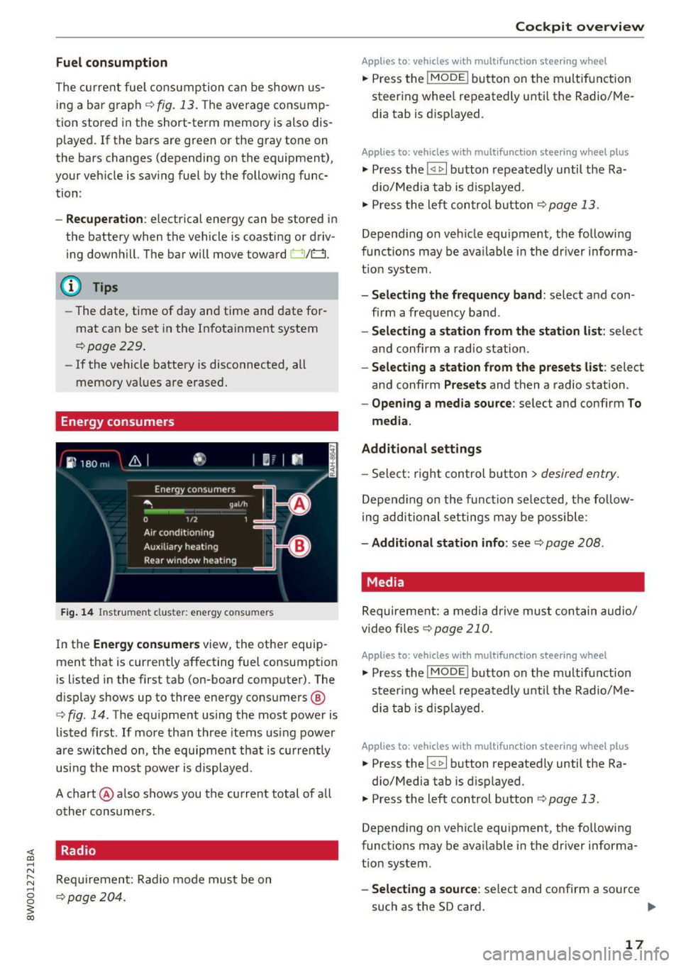
Energy consumers
Fig. 14 Instrument cluste r: energy consu mers
In the Energy consumers view, the other equip
ment that is currently affecting fuel consumption
is listed in the first tab (on-board computer) . The
display shows up to three energy consumers @
¢ fig. 14. The equipment using the most power is
listed first . If more than three items using power
are switched on, the equipment that is currently
using the most power is displayed.
A chart @ also shows you the current total of all
other consumers .
Radio
Requirement: Radio mode must be on
¢page 204.
Cockpit overview
Applies to : vehicles with mult ifunction steering wheel
.,. Press the !MODE ! button on the multifunction
steering wheel repeatedly until the Radio/Me
dia tab is displayed.
Applies to: vehicles with mult ifunction steering wheel plus
.,. Press the !<11>1 button repeatedly until the Ra-
dio/Media tab is displayed .
.,. Press the left control button ¢
page 13.
Depending on vehicle equipment, the following
functions may be available in the driver informa
tion system.
- Selecting the frequency band: select and con
firm a frequency band.
-Selecting a station from the station list: select
and confirm a radio station.
-Selecting a station from the presets list: select
and confirm
Presets and then a radio station.
-Opening a media source: select and confirm To
media.
Additional settings
- Select: right control button > desired entry.
Depending on the function selected, the follow
ing additional settings may be possible:
-Additional station info: see¢ page 208 .
Media
Requirement: a media drive must contain audio/
video files¢
page 210.
Applies to: vehicles with multifunct ion steering wheel
.,. Press the !MODE ! button on the multifunction
steering wheel repeatedly until the Radio/Me
dia tab is displayed.
Applies to: vehicles with multifunction steering wheel plus
.,. Press the !<1 1>I button repeatedly until the Ra-
dio/Media tab is displayed .
.,. Press the left control button ¢
page 13.
Depending on vehicle equipment, the following
functions may be available in the driver informa
tion system.
- Selecting a source : select and confirm a source
such as the SD card.
lli>-
17
Page 30 of 386
Cockpit over view
28
Malfunct ion Indicato r Lamp (MIL)
./
c::>page33
Diesel particulate filter*
c::>page34
Engine speed limitat ion
c::>page34
Engine oil level (MIN)
c::>page32
E ngine oil level (MAX)
c::>page308
Engine oil senso r
c::>page34
Eng ine warm -up request
c::>page34
Battery charge
<=:>page 31
Tank system
c::>page34
Washer fluid level
c::>page35
Windshield wipers
c::>page35
Remote control key
<=:>page 76
Driver's door
c::>page35
Ba ttery in remo te cont rol key
c::>page39
Bulb failure ind icator
c::>page35
H eadlight ra nge control system
c::>page35
Adapt ive lig ht*
c::>page36
Light/rain sensor
c::>page36
Active lane assist*
c::> page 113
Transmission
c::> page87
Steering lock
c::>page32
Engine start system
<=:>page 32
Electromechanical steering
c::> page 13 7
Suspension con trol*
c::> page36
Parking sys tem*
c::> page 132
E mergency call f unct io n*
<=:>page 185
Ad Blue*
c::>page300
Ad Blue*
c::>page300
Other indicator light s
--------------
Turn signals
c::> page36
Cruise contro l system*
<=:> page 93
Canad a model s:
Cruise cont rol sys tem*
<=:> page 93
Adaptive c ruise control *
¢page 98
Adaptive cruise contro l*
<=:> page 98
Adaptive cruise contro l*
¢ page 98
Adaptive c ruise contro l*
¢ page 98
Adaptive c ruise contro l*
¢ page 99, <=:>page 102
Adaptive c ruise cont ro l*
¢ page 102
Conges tion assist*
<=:>page 104
Active lane assist*
c::> page 113
Page 33 of 386
<( a, .... N ,....
N .... 0 0
3 a,
Please relea se parking br ake
Re lease the par king brake if this message ap
pears .
Please press brak e pedal to r ele as e par king
brake
To release the parking brake, press the brake
pedal and press the~ button at the same time,
or start driv ing with hill start ass ist
¢ page 82,
Starting from a stop .
(D Tips
For additional information on the parking
brake, refer to ¢
page 81.
_L Cooling system
• Turn off engin e and che ck co olant le vel.
The coolant level is too low.
Do not continue driving and switch the engine
off. Check the coolant level ¢
page 310.
-If the coolant leve l is too low, add coolant
~ page 310. Only continue driv ing once the in
dicator light turns off.
• Coolant temperature : to o high . Let engine
run with vehicle s tati onar y
Let the eng ine run at idle for a few minutes to
cool off, until the ind icator light tu rns off.
- If the indicator light does not turn off, do not continue driving the vehicle. See an author ized
Audi dealer or author ized A udi Se rvice Facility
for assistance.
_& WARNING
- Never open the hood if you ca n see or hear
steam o r coolant escaping from the engine
compartment. This increases the risk of
burns . Wait until you no longer see or hear
steam or coolant escap ing .
- The engine compartment in any veh icle can
be a dangerous area. Stop the engine and
allow it to cool before working in the engine
compartment. A lways follow the informa
t io n found in
¢ page 304, Working in the
engine compartment.
Coc kpit o ve rv iew
(D Note
Do not continue driv ing if the . indicator
light turns on as this increases the risk of en
gine damage.
~ -Safety belt
The . indicator light stays on until the dr iver 's
and front passenger's safety belts are fastened .
Above a certa in speed, there will also be a war n
ing tone.
@ Tips
For additional informat ion on safety belts, re
fer to¢
page 245 .
0 Generator/battery
If the . or(•) indicator light t urns on , the re is a
malfunction in the generator or the vehicle e lec
t rical system .
• Electric al sy stem: malfunction! Saf ely stop
v e hicle
Do not continue dr iving and switch the engine
off . See an authorized Audi dealer or authorized
Audi Se rvice Facility for assistance .
(•j Electrical system: mal function! Re start not
po ssible . Plea se co ntac t Se rvice
Disconnecting the vehicle battery from the elec
trical system prevents it from d ischarging. Drive
to an authori zed Aud i dealer or authori zed Aud i
Service Facility immed iately .
Do not stop the engine, or you w ill not be able to
start it again. If you can no longer start the en gine, see an authori zed Audi dealer or autho riz ed
Audi Service Facility for assistance .
(•) Electri cal system: malfunction! Ple ase con
tact Se rvice
Drive to an authori zed A udi dealer or authorized
A udi Service Facility immediate ly. Because the ve
hicle battery is discharging, turn off a ll unneces
sary electrical equipment such as the rad io. See
your authori zed Aud i dealer or authori zed Audi
Service Facility if the battery charge level is too
~w . ~
31
Page 34 of 386
Cockpit overview
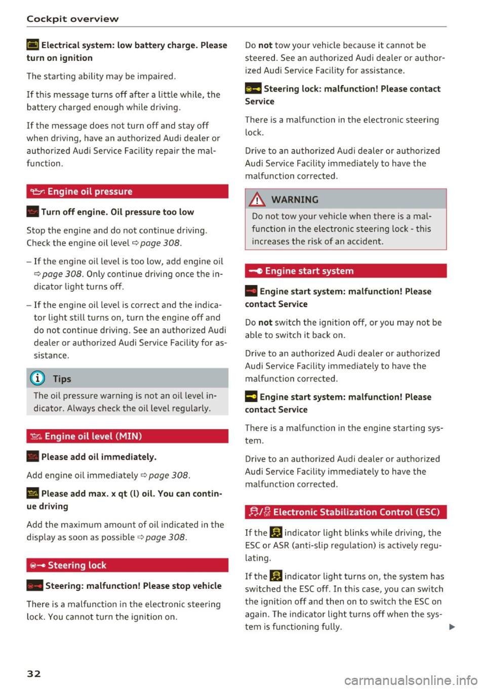
(•) Electrical system: low battery charge. Plea se
turn on ignition
The start ing ability may be impaired.
If th is message turns off after a little while , the
battery charged enough while driving.
If the message does not turn off and stay off
when dr iv ing, have an authorized Aud i dea ler or
author ized Audi Service Facility repair the mal
function .
~ Engine oil pressure
• Turn off engine. Oil pressure too low
Stop the eng ine and do not continue driving .
Check the engine oil leve l¢
page 308 .
- If the engine oil level is too low, add engine o il
c=>page 308. Only cont inue driving once the in
dicator light turns off.
- If the engine oil leve l is correct and the indica
tor light st ill turns on, turn the eng ine off and
do not continue driving. See an authorized Audi
dealer or authorized Audi Service Fac ility for as
sistance .
(D Tips
The oil pressure warning is not an o il level in
dicator . Always check the o il level regularly .
~ Engine oil level (MIN)
• Please add oil immediately.
Add engine o il immed iate ly ¢page 308 .
l!I Please add max. x qt (l) oil. You can contin
ue driving
Add the maximum amount of oil indicated in the
display as soon as possible
¢page 308.
~- Steering lock
• Steering : malfunction! Please stop vehicle
There is a malfunction in the elect ronic steering
lock . You cannot turn the ignition on.
32
Do not tow your vehicle because it cannot be
steered. See an authorized Audi dealer or author
i zed Audi Service Facility for assistance.
1!11 Steering lock: malfunction! Please contact
Service
There is a malfunction in the electron ic steering
lo ck.
Drive to an authorized Audi dealer or authorized
Audi Service Facility immed iate ly to have the
malfunction corrected .
& WARNING
Do not tow your vehicle when there is a mal
function in the electron ic steering lock -this
increases the risk of an accident .
-e Engine start system
• Engine start system: malfunction! Please
contact Service
-
Do not switch the ignition off, or you may not be
able to switch it back on.
Drive to an authorized Audi dealer or authorized
Audi Service Facility immediately to have the
malfunction corrected .
13 Engine start system: malfunction! Please
contact Service
There is a ma lfunction in the engine starting sys
tem .
Drive to an authorized Audi dealer or authorized
Audi Service Facility immediate ly to have the
malfunction corrected.
f;. 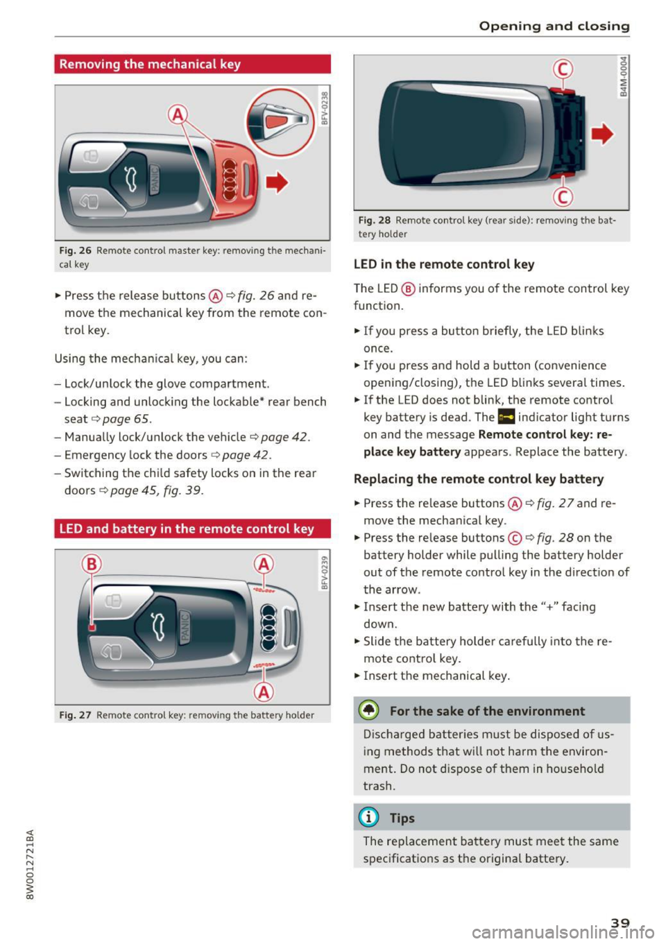
Removing the mechanical key
Fig. 26 R emote control maste r key: removing the mechani·
ca l key
• Press the release buttons @¢ fig. 26 and re
move the mechanical key from the remote con
trol key.
Using the mechan ica l key, you can:
- Lock/un lock the glove compartment.
- Locking and unlocking the lockable* rear bench
seat ¢
page 65.
-Manually lock/unlock the vehicle ¢page 42.
-Emergency lock the doors ~ page 42.
-Switching the chi ld safety locks on in the rear
doors ¢
page 45, fig. 39.
LED and battery in the remote control key
Fig. 27 Remote control key: removing the battery ho lder
Open ing and closing
Fig. 28 Remote control key (rear side): removing the bat·
tery holder
LED in the remote control key
" 0
0
0
i
~
The LED @ informs you of the remote control key
function.
• If you press a button briefly, the LED blinks
once.
• If you press and hold a button (convenience
opening/closing), the LED blinks several times .
• If the LED does not blink, the remote contro l
key battery is dead. The
1:1 indicator light turns
on and the message
Remote control key: re
place key battery
appears. Replace the battery .
Replacing the remote control key battery
• Press the re lease buttons @¢ fig. 2 7 and re
move the mechanical key .
• Press the release buttons©¢
fig. 28 on the
battery holder while pulling the battery holder
out of the remote control key in the direct ion of
the arrow .
"'I nsert th e new batte ry with the"+" fac ing
down.
"' Slide the battery holder carefully into the re
mote contro l key.
• Insert the mechanical key.
@ For the sake of the environment
Discharged batteries must be disposed of us
ing methods that will not harm the environ
ment. Do not d ispose of them in household
trash.
(D Tips
The replacement battery must meet the same
specifications as the original battery.
39
Page 43 of 386
The door cannot be opened for a brief period directly after locking it. This way you have the op
portunity to check if the doors locked correctly .
The settings in the Infotainment system deter
mine if the entire vehicle or only one of the doors
is unlocked when unlocking the vehicle
~ page 41.
A WARNING
Read and follow all WARNINGS¢&. in De
scription on page 37.
@ Tips
If your vehicle is left standing for a long peri
od of time, note the following:
- The proximity sensor switches off after a
few days to save energy. You then have to
pull once on the door handle to unlock the
vehicle and a second time to open it.
-
- The energy management system gradually
turns off unnecessary convenience functions
to prevent the battery from draining and to
maintain the vehicle's ability to start for as
long as possible. You may not be able to un
lock your vehicle using the convenience key.
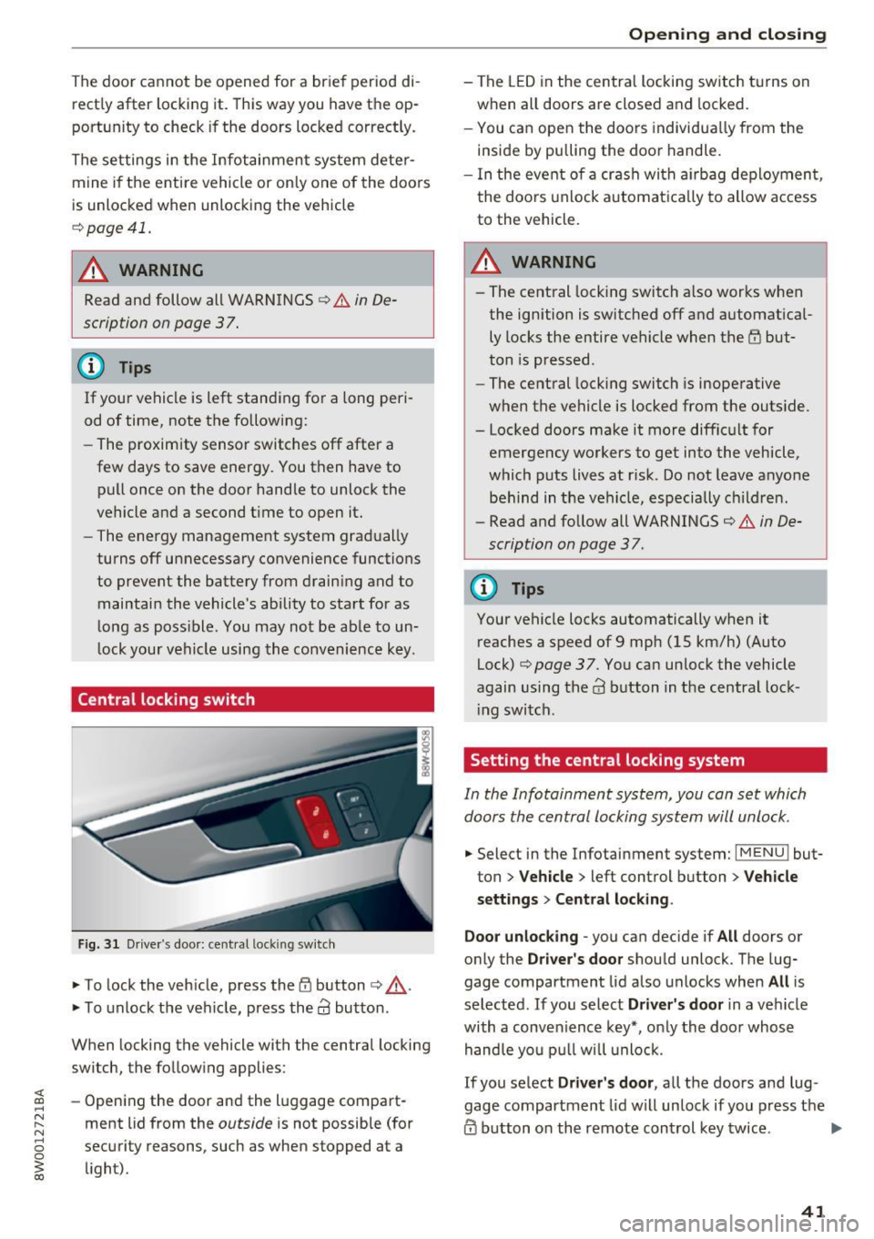
Central locking switch
Fig. 31 Driver 's door: central lock ing switch
.,. To lock the vehicle, press the tfl button ¢,& .
.,. To unlock the vehicle, press the
63 button.
When locking the vehicle with the central locking
switch, the following applies :
- Opening the door and the luggage compart
ment lid from the
outside is not possible (for
security reasons , such as when stopped at a
light).
Opening and closing
- The LED in the central locking switch turns on
when all doors are closed and locked.
- You can open the doors individually from the
inside by pulling the door handle.
- In the event of a crash with airbag deployment,
the doors unlock automatically to allow access
to the vehicle.
A WARNING
-- The central locking switch also works when
the ignition is switched off and automatical
ly locks the entire vehicle when the
tfl but
ton is pressed.
- The central locking switch is inoperative
when the vehicle is locked from the outside.
- Locked doors make it more difficult for
emergency workers to get into the vehicle,
which puts lives at risk. Do not leave anyone
behind in the vehicle, especially children.
- Read and follow all WARNINGS¢&.
in De
scription on page 3 7.
@ Tips
Your vehicle locks automatically when it
reaches a speed of 9 mph (15 km/h) (Auto
Lock)¢
page 37. You can unlock the vehicle
again using the
63 button in the central lock-
ing switch.
Setting the central locking system
In the Infotainment system, you can set which
doors the central locking system will unlock .
.,. Select in the Infotainment system: I MENU ! but
ton
> Vehicle > left control button > Vehicle
settings> Central locking .
Door unlocking
-you can decide if All doors or
only the
Driver's door should unlock. The lug
gage compartment lid also unlocks when
All is
selected . If you select
Driver's door in a vehicle
with a convenience key*, only the door whose
handle you pull will unlock.
If you select
Driver's door, all the doors and lug
gage compartment lid will unlock if you press the
@ button on the remote control key twice. .,.
41
Page 66 of 386
Sea ts and stor age
button or the buttons @or@ <* page 61,
fig. 59.
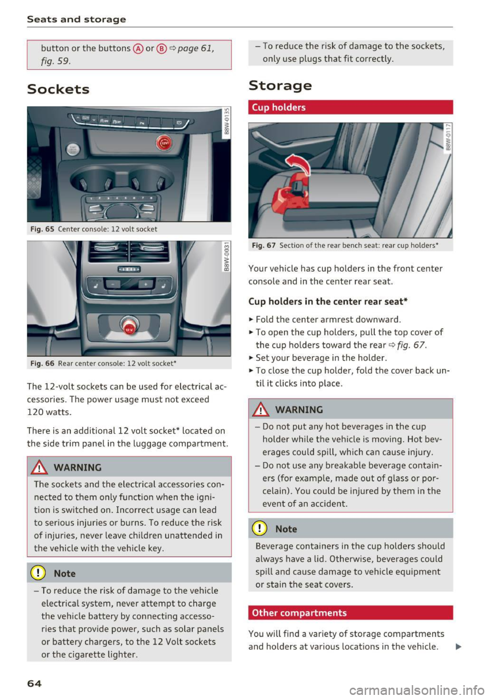
Sockets
Fig. 65 Center console: 12 volt socket
Fig. 66 Rear center console: 12 volt socket*
The 12 -volt sockets can be used for electrical ac
cessories. The power usage must not exceed
120 watts.
There is an additional 12 vo lt socket* located on
the side trim panel in the luggage compartment .
_& WARNING
The sockets and the electrical accessories con
nected to them only function when the igni
tion is switched on. Incorrect usage can lead
to serious injuries or burns. To reduce the risk
of injuries, never leave ch ildren unattended in
the vehicle with the veh icle key.
(D Note
- To reduce the risk of damage to the vehicle
electr ica l system, never attempt to charge
the vehicle battery by connecting accesso ries that provide power, such as solar pane ls
or battery chargers, to the 12 Volt sockets
or the cigarette lighter.
64
- To reduce the risk of damage to the sockets,
only use plugs that fit correctly .
Storage
Cup holders
Fig. 67 Section o f th e rear bench seat: rear cup holde rs *
Your vehicle has cup holders in the front center
console and in the center rear seat .
Cup ho ld ers in the cent er rear seat*
.,. Fold the center armrest downward .
.,. To open the cup holders, pull the top cover of
the cup holders toward the rear<=>
fig. 67 .
.,. Set your beverage in the holder.
.,. To close the cup holder, fold the cover back un
til it clicks into place .
_& WARNING
-
-Do not put any hot beverages in the cup
holder while the vehi cle is moving. Hot bev
erages could spill, which c an cause injury.
- Do not use any b reakab le beve rage contain
ers (for examp le, made out of g lass or por
celain). Yo u co uld be injured by them in the
event o f an accident .
(D Note
Beverage containers in the cup holders should
a lways have a lid. Otherwise, beve rages could
sp ill and cause damage to vehicle eq uipment
or stain the seat covers.
Other compartments
You will find a var iety of storage compartments
and holders at various locations in the vehicle. ..,.
Page 80 of 386
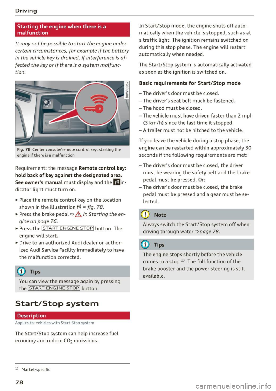
Driving Starting the engine when there is a
malfunction
It may not be possible to start the engine under certain circumstances, for example if the battery
in the vehicle key is drained, if interference is af
fected the key or if there is a system malfunc
tion.
Fig. 78 Center console/remote contro l key: starting the
eng ine if there is a m alfunction
Requirement: the message Remote control key:
hold back of key against the designated area.
See owner's manual must display and the D)in
dicator light must turn on.
.. Place the remote control key on the location
shown in the illustration
y>l) ~ fig. 78.
.. Press the brake pedal~ A in Starting the en
gine on page
76.
.. Press the l~S_T_A_R_T_E_N_G_I_N_E_S_T_O_P_I button . The
engine will start .
.. Drive to an authorized Audi dealer or author
ized Audi Service Facility immediately to have
the malfunction corrected.
(D Tips
You can view the message again by pressing the
I START ENGINE STOP! button.
Start/Stop system
Description
App lies to: ve hicles w ith S ta rt-Sto p system
The Start/Stop system can help increase fuel
economy and reduce CO2 emissions.
l ) Market -spe cific
78
In Start/Stop mode, the engine shuts off auto
matically when the vehicle is stopped, such as at
a traffic light. The ignition remains switched on
during this stop phase. The engine will restart automatically when needed.
The Start/Stop system is automatically activated as soon as the ignition is switched on.
Basic requirements for Start/Stop mode
-The driver's door must be closed.
- The driver 's seat belt much be fastened.
- The hood must be closed .
- The vehicle must have driven faster than
2 mph
(3 km/h) since the last time it stopped .
- A trailer must not be hitched to the vehicle .
If you leave the vehicle during a stop phase, the
engine can be restarted within approximately 30
seconds if the following requirements are met:
- The driver's door must be closed , the driver
must be wearing the safety belt and the brake
pedal must be pressed . Or:
- The driver's door must be closed, the brake
pedal must be pressed and a gear must be se
lected.
({D Note
Always switch the Start/Stop system off when
driving through water
~page 78.
(D Tips
The engine stops shortly before the vehicle
comes to a stop
l). The full function of the
brake booster and the power steering is still
available.
Page 81 of 386

Stopping and starting the engine
Applies to: vehicles with Start-Stop system
Fig. 79 Instrument cluster : eng ine sw itched off (s top
p hase)
~ B rake the ve hicle to a stop. The engine stops
shortly before the vehicle comes to a stop or if
the vehicle is stationa ry
1l. Keep your foot on
the brake pedal. The
II indicator light appears
in the stat us line at the bottom of the instru
ment cluster d isplay. The needle in the tachom
eter also moves into the READY
1l position .
~ The engine starts aga in when you take your
foot off the b rake pedal.
If the park ing brake is
set, the engine w ill only start aga in when the
a cce le rator pedal is p ressed
1>. The indica tor
li gh t turns off.
Additional information The engine stops i n the P, N and D selector lever
positions .
If you select the R pos ition dur ing a Stop phase ,
the eng ine will start again .
Select the P pos ition quickly to p revent the en
g ine from starting unintentionally when sh ift ing
through R.
You can determine for yourself if the engine will
stop or not by reducing or increasing the amount
of force you use to press the brake pedal. For ex
ample, if you only lig htly press on the brake ped
al in stop-and-go traff ic or when turning, the en
g ine will not switch off when the vehicle is sta
tionary . As soon as you press the brake down
ha rder, the eng ine will switch off.
l l Ma rket -spe cific
Drivi ng
(D Tips
- Press the bra ke peda l during a Stop phase
to keep the vehicle from rolling.
- The ignition will turn off if yo u press the
!START ENGINE STOPI butto n dur ing a stop
phase. The needle in the tachometer moves
into the
OFF position.
General information
Applies to: vehicles with Start-Stop system
The standard Start/Stop mode con be canceled
for different system-related reasons.
F ig. 80 Instrument cluste r: eng ine stop temporarily un
ava ilable
Engine does not switch off
Before and dur ing each stop phase, the system
checks if certain conditions have been met. For
example, the eng ine will not switch off in the fol
lowing situations:
- The engine has not reached the minim um re
quired temperature for Start/Stop mode.
- The inte rior temperature selected by the A/C
system has not been reached.
- The outside temperature is extremely high/low.
- The windsh ield is being defrosted .
- The battery charge level is too low .
- The steering wheel is turned at a sharp angle o r
is moving .
- After engaging the reverse gear .
- On sharp incl ines.
- At high altitudes .
r,jj also appears in the instrument cl uster d is
play.
79