flat tire AUDI S4 2018 User Guide
[x] Cancel search | Manufacturer: AUDI, Model Year: 2018, Model line: S4, Model: AUDI S4 2018Pages: 403, PDF Size: 66.81 MB
Page 343 of 403
Wheels
&,. WARNING
-Do not use steel rims that are 17 inches or larger . Other
wise, damage to the vehicle
and an accident could result.
-For technical reasons, it is not
possible to use tires from oth
er vehicles - in some cases,
you cannot even use tires from
the same vehicle model.
-Make sure that the tires you
select have enough clearance
to the vehicle. Replacement
tires should not be chosen
simply based on the nominal
size, because tires with a dif
ferent construction can differ greatly even if they are the
same size . If there is not
enough clearance, the tires or
the vehicle can be damaged
and this can reduce driving
safety and increase the risk of an accident.
-Only use tires that are more than six years old when abso
lutely necessary and drive
carefully when doing so .
-Do not use run-flat tires on your vehicle. Using them when
not permitted can lead to ve
hicle damage or accidents.
342
-If you install wheel covers on the vehicle, make sure they al
low enough air circulation to
cool the brake system. If they
do not, this could increase the
risk of an accident.
Tire wear /damage
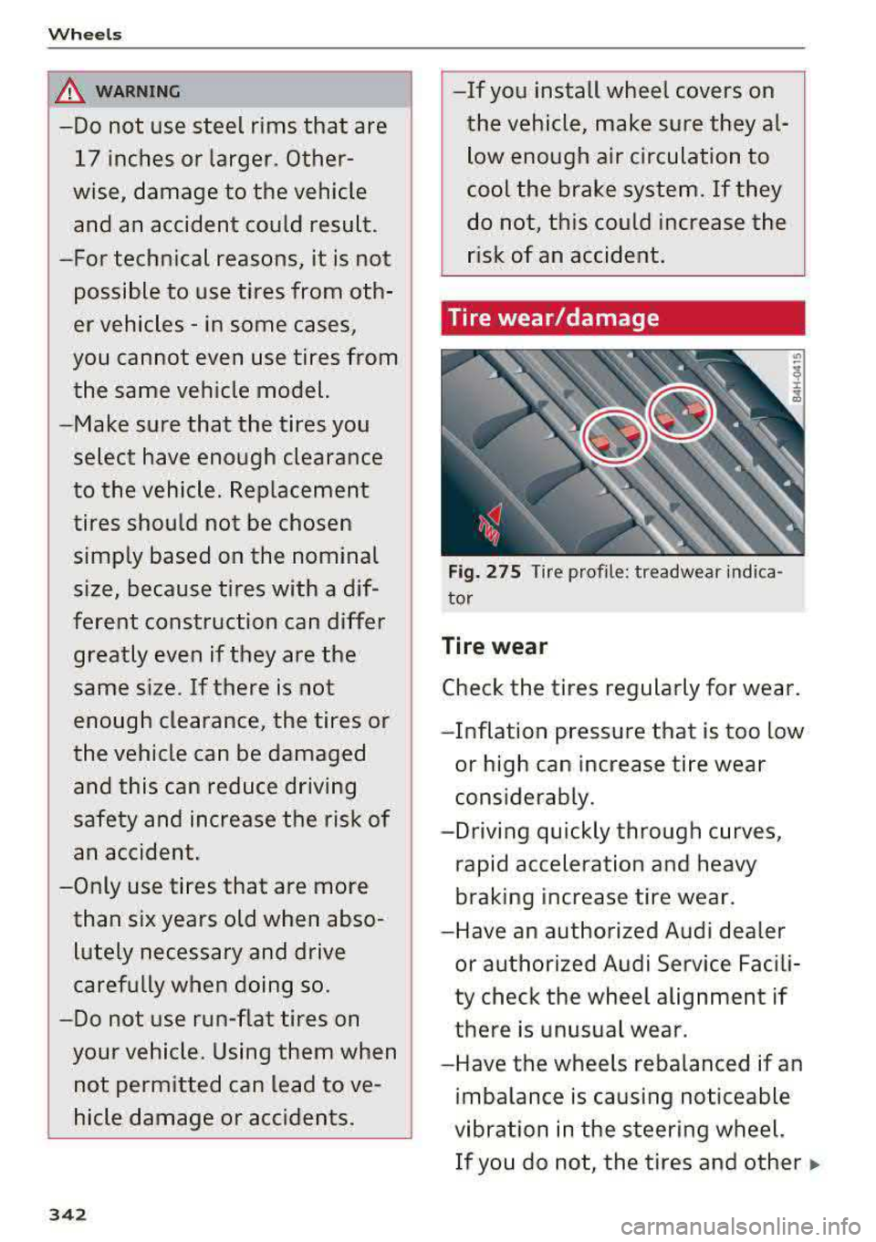
Fig. 275 Tire profile: treadwear indica
tor
Tire wear
Check the tires regularly for wear.
-Inflation pressure that is too low
or high can increase tire wear
considerably.
- Driving quickly through curves,
rapid acceleration and heavy
braking increase tire wear.
-Have an authorized Audi dealer or authorized Audi Service Facili
ty check the wheel alignment if
there is unusual wear .
-Have the wheels rebalanced if an
imbalance is causing noticeable
vibration in the steering wheel. If you do not, the tires and other
..
Page 348 of 403
0 C0 .-< N ..... N .-< 0
~ a:,
.&_ WARNING
Please note the important safe
ty precautions regarding tire
pressure
¢ page 344 and load
limits
¢ page 347 .
Tires and vehicle load limits
There are limits to the amount of
load or weight that any vehicle
and any tire can carry. A vehicle
that is overloaded will not handle
well and is more difficult to stop.
Overloading can not only lead to
loss of vehicle control, but can al
so damage important parts of the
vehicle and can lead to sudden
tire failure, including a blowout and sudden deflation that can
cause the vehicle to crash.
Your safety and that of your pas sengers also depends on making
sure that load limits are not ex
ceeded. Vehicle load includes ev
erybody and everything in and on
the vehicle. These load limits are
technically referred to as the vehi cle's
Gross Vehicle Weight Rat
ing
("GVWR").
The "GVWR" includes the weight
of the basic vehicle, all factory in
stalled accessories , a full tank of
fuel, oil, coolant and other fluids
Wheels
plus maximum load. The maxi
mum load includes the number of
passengers that the vehicle is in
tended to carry ("seating capaci
ty") with an assumed weight of
150 lbs (68 kg) for each passen
ger at a designated seating posi
tion and the total weight of any
luggage in the vehicle. If you tow
a trailer, the weight of the trailer
hitch and the tongue weight of
the loaded trailer must be includ ed as part of the vehicle load .
The
Gross Axle Weight Rating
( " GAWR ") is the maximum load
that can be applied at each of the
vehicle's two axles.
The fact that there is an upper
limit to your vehicle 's Gross Vehi
cle Weight Rating means that the
total weight of whatever is being
carried in the vehicle (including
the weight of a trailer hitch and
the tongue weight of the loaded
trailer) is limited. The more pas
sengers in the vehicle or passen
gers who are heavier than the
standard weights assumed mean
that less weight can be carried as luggage.
The Gross Vehicle Weight Rating and the Gross Axle Weight Rating
.,.
347
Page 349 of 403
Wheels
are listed on the safety compli
ance sticker on the driver's side B pillar respectively on the front
end of the driver's door.
& WARNING
-
Overloading a vehicle can cause
loss of vehicle control, a crash
or other accident, serious per
sonal injury, and even death.
-Carrying more weight than your vehicle was designed to carry will prevent the vehicle
from handling properly and increase the risk of the loss of
vehicle control.
-The brakes on a vehicle that
has been overloaded may not
be able to stop the vehicle
within a safe distance .
-Tires on a vehicle that has been overloaded can fail sud
denly, including a blowout and
sudden deflation, causing loss of control and a crash .
-Always make sure that the to tal load being transported -
including the weight of a trail
er hitch and the tongue
weight of a loaded trailer -
does not make the vehicle
heavier than the vehicle's
Gross Vehicle Weight Rating.
348
Determining correct load
limit
Use the example below to calcu
late the total weight of the pas
sengers and luggage or other
things that you plan to transport so that you can make sure that
your vehicle will not be overload
ed.
Steps for Determining Correct Load Limit
1. Locate the statement "THE
COMBINED WEIGHT OF OCCU
PANTS AND CARGO SHOULD
NEVER EXCEED XXX KG OR XXX
LBS" on your vehicle's placard
(tire inflation pressure label)
¢ page 344, fig. 277.
2. Determine the combined
weight of the driver and pas sengers that will be riding in
your vehicle.
3. Subtract the combined weight
of the driver and passengers
from
"XXX" kilograms or "XXX"
pounds shown on the stick
er ¢ page 344, fig. 2 77.
4. The resulting figure equals the
available amount of cargo and luggage load capacity . For ex
ample, if the "XXX" amount
equals 1400 lbs. and there will
.,.
Page 352 of 403
a co .... N ,....
N .... 0 0
3 co
Low -profile tires can wear out faster than stand
ard tires.
Summer tires are not su itable for cold weather,
snow or b lack ice. If you are driving in these con
ditions, use winter or all season tires
¢ page 349.
Uniform tire quality grading
-Tread wear
- Traction AA AB C
- T emperature ABC
Qual ity grades can be found where app licable on
the t ire side wa ll between tread shou lde r and
maximum sect ion w idth
¢page 334, fig. 274.
For e xample : Tread wear 200 , Traction AA, Tem
pe rature
A .
All passenger car tires must conform to Federal
Safety Requirements in addition to these grades.
Tread w ear
The tread wear grade is a comparative rating
based on the wear rate of the tire when tested
under controlled conditions on a specified gov
ernment test course.
F or example, a tire graded 150 would wear one
and one ha lf
(1 1/2) times as well on the govern
ment course as a tire graded 100.
The relative performance of tires depends upon
the actual conditions of their use, however, and
may depart significant ly from the norm due to
variations in driving hab its, service practices and
d ifferences i n road characteristics and climate.
Tracti on
The traction grades, from highest to lowest, are
AA, A, Band
C. Those grades represent the tire's
ab ility to stop on wet pavement as measured un
der controlled conditions on specified govern
ment test surfaces of asphalt and concrete . A tire
marked C may have poor traction performance
¢ _& .
Temper ature
The temperature grades are A (the h ighest), B,
and C, representing the tire's resistance to the
Wh eel s
generat ion of heat and its ability to dissipate
heat when tested under controlled conditions on
a specified indoor laboratory test wheel.
Sustained h igh temperature can cause the mate
ria l of the tire to degenerate and reduce tire life,
and excessive temperature can lead to sudden
tire
failure ¢.& .
The grade C corresponds to a level of per form
ance which all passenger car tires must meet un
der the Federal Motor Vehicle Safety Standard
No. 109. Grades Band A represe nt higher levels
of performance on the laboratory test wheel than
the minimum requ ired by law.
A WARNING c,...._ -
The tract ion grade assigned to this t ire is
based on straight-ahead braking traction
tests, and does not include acceleration, co r
nering, hyd roplaning or pea k traction cha rac
terist ics.
A WARNING
The temperature grade for this tire is estab
lished for a tire that is properly inflated and
not overloaded . Excessive speed, underinfla
tion, or excessive loading, either separately or
i n comb inat ion, can cause heat bu ildup and
possib le tire fai lure.
A WARNING
-Temperature grades apply to tires that are
properly inflated and not over or under inflat
ed.
Tire pressure monitoring system
ill General notes
Each tire, including the spare (if provided),
.
should be checked monthly when cold and inflat-
ed to the i nflat io n pressure recommended by the
vehicle manufacturer on the veh icle placard or
t ir e infla tion p ressure labe l. (If your ve hicle has
ti res of a different size t han t he si ze ind icated on
IIJi,-
351
Page 353 of 403

Wheels
the vehicle placard or tire inflation pressure la
bel, you should determine the proper tire
inflation pressure for those tires).
As an added safety feature, your vehicle has been
equipped with a tire pressure monitoring system (TPMS) that illuminates a low tire pressure tell
tale when one or more of your tires is significant
ly under-inflated. Accordingly, when the low tire
pressure telltale illuminates, you should stop and
check your tires as soon as possible, and inflate
them to the proper pressure . Driving on a signifi
cantly under-inflated tire causes the tire to over
heat and can lead to tire failure. Under-inflation
also reduces fuel efficiency and tire tread life,
and may affect the vehicle's handling and stop
ping ability.
Please note that the TPMS is not a substitute for
proper tire maintenance, and it is the driver's re
sponsibility to maintain correct tire pressure,
even if under-inflation has not reached the level
to trigger illumination of the TPMS low tire pres
sure telltale.
Your vehicle has also been equipped with a TPMS
malfunction indicator to indicate when the sys
tem is not operating properly. The TPMS mal
function indicator is combined with the low tire
pressure telltale. When the system detects a
malfunction, the telltale will flash for approxi
mately one minute and then remain continuously
illuminated . This sequence will continue upon
subsequent vehicle start-ups as long as the mal
function exists .
When the malfunction indicator is illuminated,
the system may not be able to detect or signal low tire pressure as intended. TPMS malfunctions
may occur for a variety of reasons, including the
installation of replacement or alternate tires or
wheels on the vehicle that prevent the TPMS
from functioning properly. Always check the TPMS malfunction telltale after replacing one or
more tires or wheels on your vehicle to ensure
that the replacement or alternate tires and
wheels allow the TPMS to continue to function
properly .
352
· If the tire pressure monitoring indicator
appears
The tire pressure indicator in the instrument
cluster informs you if the tire pressure is too low
or if there is a system malfunction.
Using the ABS sensors, the tire pressure monitor
ing system compares the tire tread circumfer
ence and vibration characteristics of the individu
al tires. If the pressure changes in one or more
tires, this is indicated in the instrument cluster
display with an indicator light
[I] and a message.
If only one tire is affected, the location of that
tire will be indicated.
The tire pressures must be stored in the Infotain
ment system again each time the pressures
change (switching between partial and full load
pressure) or after changing or replacing a tire on
your vehicle
c:> page 353. The tire pressure moni
toring system only monitors the tire pressure you
have stored . Refer to the tire pressure label for
the recommended tire pressure for your vehicle
c:> page 344, fig . 2 77.
Tire tread circumference and vibration character
istics can change and cause a tire pressure warn
ing if:
- the tire pressure in one or more tires is too low
- the tires have structural damage
- the tire was replaced or the tire pressure was
changed and it was not stored
c:> page 353
- tires that are only partially used are replaced
with new tires
Indicator lights
[I]-Loss of pressure in at least one tire c:> ,&..
Check the tires and replace or repair if necessary.
Check/correct the pressures of all four tires and
store the pressure again in the Infotainment sys
tem
c:> page 353.
mm (Tire Pressure Monitoring System) Tire
pressure: malfunction! See owner's manual.
If
mm appears after switching the ignition on or
while driving and the
[I] indicator light in the in
strument cluster blinks for approximately one minute and then stays on, there is system mal-
function. Try to store the correct tire pressures
IJJ,,,
Page 361 of 403
Emergency assistance
Emergency assistance
General information
... Park the vehicle as far as possible from moving
traffic in the event of a breakdown. In the event
of a flat tir e, park the vehicle on a level surface .
It you are on a steep hill, be especially careful.
.,. Set the parking brake .
.,. Switch the emergency flashers on .
... Have the passengers exit the vehicle . They
should move to a safe place, for example be
hind a guard rail.
_& WARNING
Follow the steps given above . This is for your
protection and the for the safety of other driv
ers.
Equipment
Vehicle tool kit/tire mobility kit/vehicle
jack
Applies to: vehicles with the vehicle tool kit, tire mobility kit
and veh icle jack
Applies to: sedan
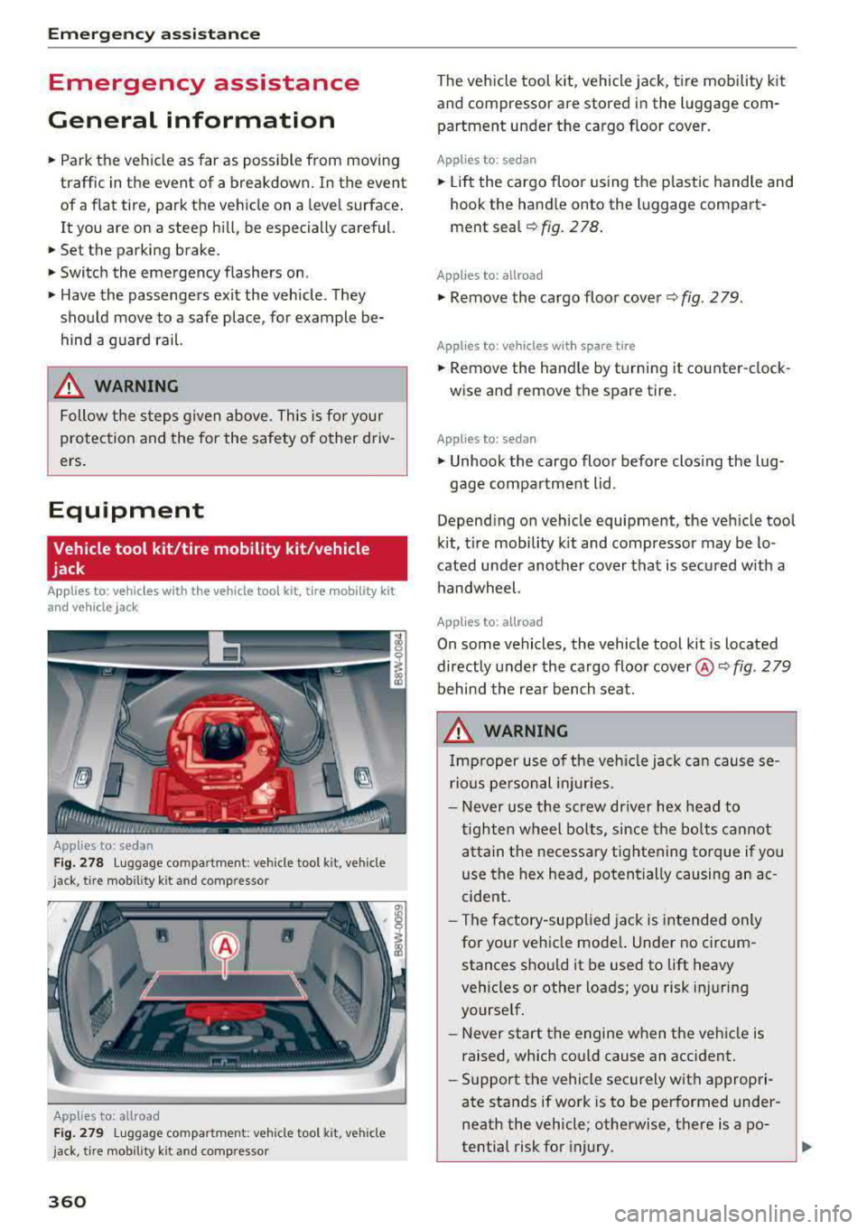
Fig. 278 L uggage compartmen t: vehicle too l kit , ve hicle
j ack, tire mob ility kit an d comp resso r
Applies to: allroad
Fig. 279 Lug gage compa rtmen t: ve hicl e tool kit, v ehicle
j ack, tir e mobil ity k it and comp resso r
360
The vehicle tool kit, vehicle jack, tire mobility kit
and compressor are stored in the luggage com
partment under the cargo floor cover.
Applies to: sedan
.,. Lift the cargo floor using the plastic handle and
hook the hand le onto the luggage compart
ment
seal ~ fig. 2 78.
Applies to: allroad
... Remove the cargo floor cover ~ fig. 279 .
Applies to : vehicles with spare tire
... Remove the handle by turning it counter-clock
wise and remove the spare tire.
Appl ies to: sedan
.,. Unhook the cargo floor before closing the lug-
gage compartment lid .
Depend ing on vehicle equipment, the vehicle tool
kit, tire mobility kit and compressor may be lo
cated under another cover that is secured w ith a
handwheel.
Applies to : allroad
On some vehicles, the vehicle tool kit is located
directly under the cargo floor
cover@~ fig. 2 79
behind the rear bench seat.
_& WARNING
Impr oper use of the vehicle jack can cause se
rious personal injur ies.
- Never use the screw driver hex head to
tighten wheel bolts, since the bolts cannot
attain the necessary tightening torque if you
use the hex head, potentially causing an ac
cident.
- The factory-supp lied jack is intended only
for your vehicle mode l. Under no circum
stances should it be used to lift heavy
veh icles or other loads; you risk injuring
yourself.
- Never start the engine when the vehicle is
raised, which cou ld cause an accident.
- Support the vehicle securely with appropri
ate stands if work is to be performed under
neath the vehicle; otherwise, there is a po
tential risk for injury.
Page 363 of 403
Emergency assistance
Repairing tires
Applies to: vehicles w ith tire mob ility k it
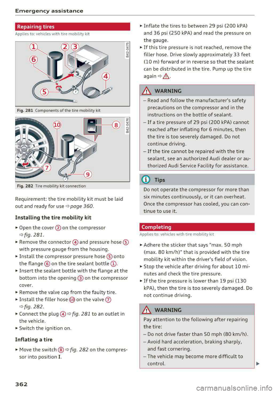
Fig. 281 Components of the tire mobility kit
F ig. 282 Tire mobility k it connec tion
Requirement: the tire mobility kit must be laid
out and ready for use
o page 360.
Installing the tire mobility kit
.. Open the cover @on the compressor
¢fig. 281 .
.. Remove the connector @) and pressure hose®
with pressure gauge from the housing.
• Install the compressor pressure hose ® onto
the f lange @ on the tire sea lant bottle
(D .
.. Insert the sealant bottle with the flange at the
bottom into the opening @ on the compresso r
cover.
.. Remove the valve cap from the fau lty tire.
.. Install the filler hose @) on the valve (J)
ofig. 282 .
.. Connect the plug@¢ fig. 281 to an outlet in
the vehicle.
.. Switch the ignition on.
Inflating a tire
.. Move the switch @ o fig. 282 on the compres
sor into position
I.
362
.. Inflate the tires to between 29 psi ( 200 kPA)
and 36 psi (250 kPA) and read the pressur e on
the gauge .
.. If this tire pressure is not reached, remove the
filler hose. Drive slowly approximately 33 feet
(10 m) forward or in reverse so that the sea lant
can be distributed in the tire. Pump up th e tire
aga in¢ ,&.
.
.&_ WARNING
-Read and follow the manufacturer's safety
precaut ions on the compressor and in the
instructions on the bottle of sea lant .
- If a tire pressure of 29 psi (200 kPA) cannot
reached after inflating for 6 minutes, then
the tire is too severely damaged. Do not
continue driving.
- If the tire cannot be repa ired with the tire
sealant, see an authorized Audi dealer or au
thorized Audi Service Facility for assistance.
(D Tips
Do not operate the compressor for more than
six minutes continuously, or it can overheat.
Once the compressor has cooled, you can con
tinue to use it.
Completing
App lies to : vehicles wit h tire mob ility kit
.. Adhere the sticker that says "max. SO mph
(max . 80 km/h)" that is provided with the tire
mob ility kit with in the driver's field of vision.
.. Stop the vehicle after driv ing for about 10 mi
nutes and check the tir e pressure.
.. If the tire press ure is lower than 19 psi (130
kPA), then the tire is too severely damaged. Do
not continue driving .
.&_ WARNING
Pay attention to the following after repairing
the tire:
- Do not drive faster than SO mph (80 km/h).
- Avoid hard acceleration, braking sharply,
and fast cornering .
- The vehicle may become more difficult to
con trol.
Page 364 of 403
-If the t ire is too severely damaged , see an
authorized Aud i dealer or authorized Aud i
Service Facility for assistance .
@ For the sake of the environment
You can give the used tire sealant bottle to an
author ized Audi dealer or authorized A udi
Serv ice Facility for disposal.
@ Tips
Remember to obtain a new bottle of sea lant
from an authorized Audi dea ler or authorized
Audi Service Facility after repair ing a tire.
Replacing a wheel
Preparation
You must complete the preparation before
changing a tire .
.,. Read and follow the important safety precau
tions ~ page 360 .
.,. Set the parking brake .
Applies to: ve hicles with man ua l transmiss ion
.,. Shift in to 1st gear.
Applies to: ve hicles with automat ic t ra n smi ssio ns
.,. Select the P selector leve r pos ition .
.,. When towing a trailer: disconnect the tra iler
from your veh icle .
.,. Lay out the veh icle tool kit 9 page 360 and the
spare
tire ~ page 367 .
.,. Switch the ignition off .
A WARNING
When using the vehicle jack* on a road with a
steep hill or offroad, you must take extra pre
cautions to prevent the vehicle from rolling .
Use suitab le objects to b lock the front and
back of the wheel that is diagonal from the
wheel with the flat tire.
A WARNING
You or your passengers could be in ju red wh ile
chang ing a wheel if you do not follow these
safety precautions :
Emergen cy a ssis tanc e
-If you have a flat tire, move a safe distance
off the road. Turn off the eng ine, turn the
emergency flashers on and use other warn
ing dev ices to alert other motorists .
- Make sure that passengers wait in a safe
place away from the vehicle and well away
from the road and traff ic .
- To help prevent the veh icle from moving
suddenly a nd possib ly slipping off the jack*,
always fully set the park ing brake and block
the front and back of the wheel diagonally opposite the wheel being changed. When
one front wheel is lif ted off the gro und,
p la cing the Automa tic Transmission in P
(Park) will
not prevent the vehicle from
moving.
- Before you change a wheel, be sure the
g ro und is leve l and firm. If necessary, use a
sturdy board under the jack *.
- Always store the vehicle tool kit, the jack *
a nd the replaced tire in the luggage com
partment
~ page 259 .
(D Tips
Obey all laws .
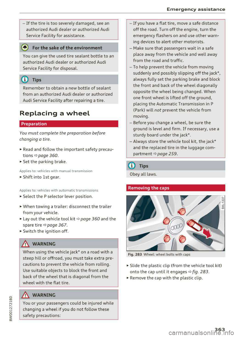
Removing the caps
Fig. 283 W hee l: whee l bolt s w ith ca ps
.,. Slide the p lastic clip (from the veh icle tool k it)
on to the cap unt il it
engages ~ fig. 283.
.,. Remove the cap with the p lastic clip.
363
Page 365 of 403
Emergency assistance
Loosening the wheel bolts
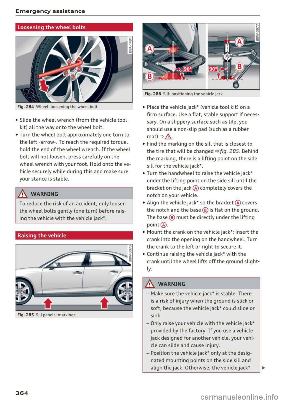
Fig. 284 Wheel: loosening the wheel bolt
• Slide the wheel wrench (from the vehicle tool
kit) all the way onto the wheel bolt.
• Turn the wheel bolt approximately one turn to
the left -arrow-. To reach the required torque,
hold the end of the wheel wrench. If the wheel
bolt will not loosen, press carefully on the
whee l wrench with your foot. Hold onto the ve
hicle securely while during this and make sure
your stance is stable .
A WARNING
To reduce the risk of an accident, only loosen
the wheel bolts gently (one turn) before rais
ing the vehicle with the veh icle jack*.
Raising the vehicle
Fig . 28S Sill panels: markings
364
Fig. 286 Sill: positio ning the vehicle jack
• Place the veh icle jack* (vehicle tool kit) on a
firm s urface. Use a flat, stable support if neces
sary. On a slippery surface such as tile, you
should use a non-slip pad (such as a rubber
mat)¢ &.
• Find the marking on the sill that is closest to
the tire that will be
changed¢ fig. 2 85 . Behind
the marking, there is a lifting point on the side
sill for the vehicle jack*.
• Turn the handwheel to raise the vehicle jack*
under the lifting point on the side sill until the
bracket on the jack @ completely covers the
notch on your vehicle.
• Align the vehicle jack* so the bracket @covers
the notch and the base ® is flat on the ground.
The base ® must be directly under the lifting
point @.
• Mount the crank on the vehicle jac k*: insert the
crank into the opening on the handwheel. Turn
the crank to the left or right to secure it.
• Continue ra is in g the veh icle jack* with the
crank until the wheel lifts off the ground slight
ly.
A WARNING
- Ma ke sure the vehicle jack* is stable. Th ere
is a risk of injury when the ground is slick or
soft, because the vehicle jack* could slide or
sink.
- Only raise your vehicle with the vehicle jack*
provided by the factory . If you use a vehicle
jack designed for another vehicle, your vehi
cle can slide and cause injury.
- Position the vehicle jack* only at the desig
nated mounting points on the side sill and
align the jack. Otherwise, the vehicle jack*
Page 367 of 403
Emergency assistance
CJ) Note
When removing or installing the whee l, the
r im could hit the brake rotor and damage the
rotor. Work ca ref ull y and have a second pe r
son help you.
@ Tips
- When mounting tires w ith unidirectional
tread design
ma ke s ure the t read pattern is
po inted the r ight
way ¢ page 366.
-The wheel bolts should be clean and easy to
turn. Check for d irt and cor ros ion on the
mating s urfaces of both the wheel and the
h ub. Remove all dirt from t hese surfaces be
fo re re mo unt ing th e wheel.
Unidirectional tires
A unid irec tional tire p rofile is ident ified by a rrows
th at poin t in the run nin g dir e cti on o n the tire
sidewall. You mus t always a dhere to the speci
fied running d irec tion. This is necessary ens ure
the t ire's optim um perfo rmance in regar d to a d
hes ion, r unning noise, fr iction and hydrop la ning.
T o be nefi t fu lly fro m the adv ant ages of the uni
d irect ional tire des ign, you sho uld replace faulty
tires as soon as possi ble an d restore the correct
r u nning di rect io n on all of the tires.
Finishing
.,. Reinstall the caps on the whee l bolts if neces
sary .
.,. Store the vehicle tool kit in its designated
place .
.,. If the re m oved whee l does not fi t in the spa re
whee l we ll, store it se cur ely in t he luggage
com partmen t¢ page 2 59.
.,. Check the tire press ure on the ins talled whee l
as soon as possible.
.,. Co rrect the tire p ressure and store it in the I n
fota inment system
¢ page 353 .
.,. The wheel bo lt tightening specification must be
90 ft lbs (120 Nm) . Check it as soon as poss ible
with a torq ue wrenc h. Dr ive ca refully unt il t hen .
.,. Have th e faulty wheel rep laced as quic kly as
poss ible.
366
(D Tips
-If you not ice that t he w heel bo lts a re cor
rode d and difficult to tur n while changing a
t ir e, t hey s hou ld be replaced befo re yo u
check the t ightening torque.
- Drive at red uce d speed unti l yo u have the
t ightening to rques checked.
· Notes on wheel changing
Please read t he informat ion¢ page 341 if yo u
are going to use a replacemen t tire which is d if
ferent from the tires on yo ur vehicle .
After you change a tire:
- Check the tire pressure on the replacement
tire immediately after installation.
- Have the wheel bolt tightening torque
checked with a torque wrench as soon as pos
sible by your authorized Audi dealer or quali
fied workshop.
- With steel and alloy wheel rims, the wheel
bolts are cor rectly tightened at a torque of
90
ft lbs (120 Nm) .
- If you notice that the wheel bolts are corroded
and difficult to turn while changing a tire,
they should be replaced before you check the
tightening torque .
- Replace the flat tire with a new one and have
it installed on your vehicle as soon as possi
ble. Remount the wheel cover .
Until then, dr ive with e xtra care and at reduced
speeds.
A WARNING
- If you are going to equip yo ur vehicle wi th
t ires or r ims which diffe r from those which
we re fac to ry insta lled , th en be su re to read
t he
informa tion ¢ page 341.
- Always make sure the damage d w heel or
ev en a fla t tire and the jack* an d tool kit are
p ro p erl y se cured in t he lug gage com part
me nt an d ar e no t lo o se in the pas senge r
c o mp artme nt.
- I n an ac cident or su dde n man euver they
co uld fl y forw ard , injur ing an yone i n t he ve
hicle.