radio AUDI S4 CABRIOLET 2009 Owners Manual
[x] Cancel search | Manufacturer: AUDI, Model Year: 2009, Model line: S4 CABRIOLET, Model: AUDI S4 CABRIOLET 2009Pages: 340, PDF Size: 77.32 MB
Page 27 of 340
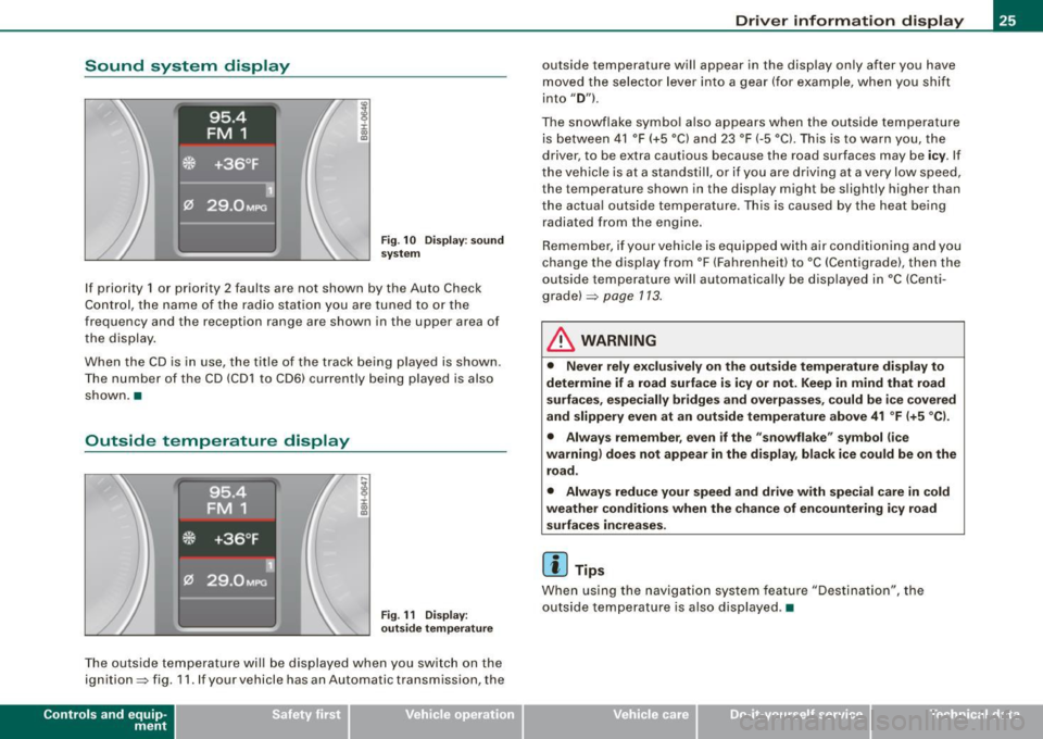
Sound system display
Fig . 1 0 Displ ay : soun d
syste m
If priority 1 or priority 2 faults are not shown by the Auto Check
Control, the name of the radio station you are tuned to or the
frequency and the reception range are shown in the upper area of
the display .
When the CD is in use , the title of the track being p layed is shown .
The number of the CD (CD1 to CD6) currently being played is also
shown. •
Outside temperature display
Fig . 11 Dis pla y :
o utsi de tem perature
The outside temperature will be displayed when you switch on the
ignition=> fig. 11 . If your vehicle has an Automa tic transmission , the
Contro ls and eq uip
ment
Dri ver informa tio n di spl ay
outside temperature will appear in the disp lay only after you have
moved the selector lever into a gear (for example, when you shift
into
" D ") .
The snowflake symbo l a lso appears when the outside temperature
is between 41 °F (+5 °C) and 23 °F (-5 °Cl. Th is is to warn you, the
driver, to be extra cautious because the road surfaces may be
i c y . If
the vehicle is at a standstill, or if you are driving at a very low speed, the temperature shown in the display might be slightly higher than
the actua l outs ide temperature. This is caused by the heat be ing
radiated from the engine.
Remember , if your vehicle is equipped with a ir conditioning and you
change the display from °F (Fahrenhei t) to °C (Centigrade), then the
outside temperature will automatically be displayed in
•c (Centi
g rade) =>
page 113.
& WARNING
• Never r ely exc lusiv el y o n th e out side t emp erat ure di spl ay to
determine if a ro ad sur face is icy or not. Keep in mind that road
s urf aces , esp eci ally br idge s and overpa sses, co uld b e ic e co ve red
and slipp ery even at an out side temperature above 41 °F (+ 5 °C l.
• Alway s re memb er, eve n if the "snowflake" sy mbol (ic e
warning ) does not ap pea r in the display , b lack ice cou ld be on the
r o ad .
• Alway s reduc e your speed and driv e with sp ec ial care in cold
we ather condition s when th e chance of en countering i cy ro ad
s urf ace s incr eases.
[ i ] Tips
When using the navigation system feature "Destination", the
outside temperature is also displayed. •
~ehicle care irechnical data
Page 44 of 340
Driver information display
symbols appear in the instrument cluster display to alert the driver.
The warning light in the instrument cluster comes on when the
tire is significantly underinflated .
The warning light _, also lights up during a system failure.
When the wheel is turning, the system receives radio signals from
sensors located inside each tire .
A factory spare wheel is delivered with sensor. However, the spare
wheel is not checked by the tire pressure monitoring system. Such monitoring can only occur after the spare wheel has been installed
and initialized ~
page 45.
Be aware that tire pressure is also dependent on the temperature of
the tire. For every 18 °F (10 °C) increase in tire temperature, tire pres
sure increases by about 1.5 psi (0.1 bar). The tire warms up while the
vehicle is moving and tire pressure rises. So you should adjust tire
pressure only when they are
cold, when tire temperature is roughly
the same as ambient air temperature.
In order to keep the tire pressure monitoring system properly cali
brated, tire pressure on all four tires should be checked at regular
intervals, adjusted if necessary and saved in the proper setting
(recommended pressure)~
page 43.
The tire pressure is shown on the tire pressure label. On USA vehi
cles, the tire pressure label is located on the driver's side B-pillar. On
Canada vehicles, the tire pressure label is located either on the
driver's side B-pillar or inside the fuel filler flap. The tire pressure
label lists the recommended cold tire inflation pressures for the
vehicle at its maximum capacity weight and the tires that were on
your vehicle at the time it was manufactured . For recommended tire
pressures for normal load conditions, please see chapter
~ page 277.
& WARNING
• When the tire pressure monitoring system warning light is lit,
one or more of your tires is significantly under -inflated. You should
stop and check your tires as soon as possible, and inflate them to
& WARNING (continued)
the proper pressure as indicated on the vehicle's tire pressure
label
~ page 271. Driving on a significantly under-inflated tire
causes the tire to overheat and can lead to tire failure. Under-infla
tion also is likely to impair the vehicle's handling and stopping ability .
• Do not adjust tire pressure when tire temperature is excessive.
This could lead to serious tire damage and even cause the tire to
burst, with the additional danger of an accident.
For the sake of the environment
Driving with under-inflated tires reduces fuel efficiency and tire
tread life.
[ i] Tips
• Each tire should be checked monthly when cold and set to the
recommended inflation pressure as specified on the tire pressure
table~
page 277 .
• The tire pressure monitoring system helps the driver to keep
track of the tire pressures . But the driver still has the responsibility
for maintaining the correct tire pressure.
• Tire pressure must only be adjusted when the temperature of the
tires is about the same as ambient air temperature.
• When tires are replaced, the sensors and valves must not be
detached or exchanged. Only the valve core needs to be replaced
and, if necessary, the valve and the wheel electronics replaced.
• If you should put different wheels and tires on your vehicle (e.g.
winter wheels and tires), you must be certain that the wheels and
tires are compatible with the tire pressure monitoring system.
Otherwise the system will register a malfunction and a fault
message will be displayed. For more information, contact your Audi
dealer. .,
Page 48 of 340
Driver inf orma tion d ispl ay
Your tire change is incomplete if you do not access the Driver Infor
mation System menu, and select and confirm
Wh eel ch ange. You
must do this each time to change a tire . The procedure can take up
to 20 minutes driving time. During this time, the sensors are read
justing to the new wheel/tire combination, and the new pressures are stored.
During the learning phase, the tire pressure monitoring system is
not available. •
Applies to vehic les: with tire pressure monitor ing system
Malfunctions
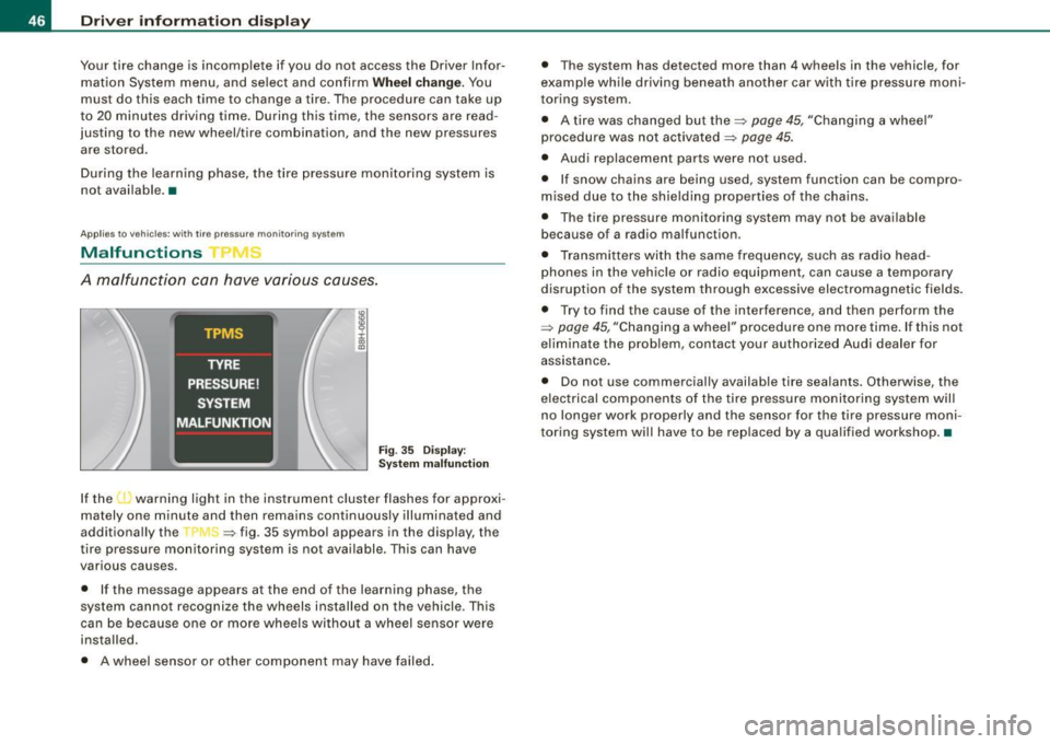
A malfunction can have various causes.
Fig . 35 Dis pl ay:
Syst em m alfu nct ion
If the 'warning light in the instrument cluster flashes for approxi
mately one minute and then remains continuously illuminated and
additional ly the --, -=> fig. 35 symbol appears in the display, the
tire pressure monitoring system is not available. This can have
various causes.
• If the message appears a t the end of the learning phase, the
system cannot recognize the wheels installed on the vehicle . This
can be because one or more wheels without a wheel sensor were
installed.
• A wheel sensor or other component may have failed. •
The system has detected more than 4 wheels in the vehicle, for
example while driving beneath another car with tire pressure moni
toring system.
• A tire was changed but the=>
page 45, "Changing a wheel"
procedure was not activated =>
page 45.
• Audi replacement parts were not used.
• If snow chains are being used, system function can be compro
m ised due to the shielding properties of the chains.
• The tire pressure monitoring system may not be ava ilable
because of a radio malfunction.
• Transmi tters with the same frequency, such as radio head
phones in the vehicle or radio equipment, can cause a temporary
disruption of the system through excessive electromagnetic fields.
• Try to find the cause of the interference, and then perform the
=>
page 45 , "Changing a wheel" procedure one more time . If this not
e liminate the prob lem, contact your authorized Audi dealer for
assistance .
• Do not use commercial ly availab le tire sealants . Otherwise, the
e lec trical components of the tire pressure monitoring system will
no longer work properly and the sensor for the tire pressure moni
toring system wi ll have to be rep laced by a qua lified workshop .•
Page 59 of 340
To unlock r ear lid
- Pu ll the switch c:::::5 ~ page 56, fig. 48 in the driver's door.
To open re ar lid
- Raise the rear lid.
The remote rear lid re lease is deactivated automatically if you lock
the rear lid using the key . This enables the driver to lock the luggage
compartment permanently with the key and prevent unwanted
access to the trunk .•
Anti-theft alarm system
Description
The anti-theft alarm triggers an alarm if anyone attempts
to break into the vehicle.
The anti -theft a larm system triggers an audible alarm and turns on
the emergency flasher if an unauthorized interference with the
veh ic le is sensed by the system.
How i s the anti -theft alarm syste m switched on ?
The anti-theft alarm system is switched on when you lock the
driver's door manually using your key, o r when you use the remote
control. The system is activated approx imately 30 seconds after the
vehic le is locked. The indicator light on top of the door trim start
fl ashing rapid ly for 30 seconds and then b link slowly.
How i s the anti -theft al arm syst em switch ed off ?
The anti-theft alarm system is switched off only when you use the
remote contro l to unlock your vehicle . If you do not open a door
with in 60 seconds after you have unlocked with the remote control,
the vehic le will lock itself again automatica lly.
Controls and equip
ment
Op ening and clo sing
If you lock just the driver's door using your key, the front
passenger's door, the rear and the fuel f iller flap remain locked.
If you use the vehicle key to unlock the driver's door, the other
doors, the rear lid and the fuel tank flap will remain locked . The
a larm system will not be deactivated unless you insert the key in the
ignition switch within 15 seconds and turn on the ignition. If you fai l
to do this, the a lar m wi ll sound.
When will the anti theft alarm system be triggered?
When the vehic le is locked, the a larm system monitors and protects
the following parts of the vehic le:
• engine compar tment
• luggage compartment
• doors
• vehic le incline
• ignition
• factory installed radio.
When the system is activated, the alarm will be triggered if one of
the doors, the engine hood or the rear lid are opened, or if the igni
tion is turned on or the radio removed or if the vehicle incline has
been changed.
The ant i-theft alarm system will also go off when you unlock the rear
lid with your key and open it. The alarm is switched off again when
you close the rear lid.
The anti-theft alarm system will also go off when the battery is d isconnected.
You can also trigge r the alarm by pressing the PANIC button on your
remote control. This will alert other people in case of emergency.
Press the
PANI C button again to turn off the a larm. .,_
Page 143 of 340
______________________________________________________ H_o_ m __ e_L _i_n _k _@_R _ __,_
9. The emergency flashers will flash three times (after
about 15-60 seconds) when the programming is
successful. Release the button on the remote control.
- To program more devices, repeat steps 4 to 9 .
10. Press and hold the trained Homelink® button and observe the ind icator light@=> page 140, fig. 151.
- If the indicator light is solid/continuous, programming is complete and your device should activate when you press and release the trained Homelink® button.
- If the indicator light blinks rapidly for 2 seconds and is
then a solid/continuous light , proceed with phase 3 to
program a rolling code device.
Phase 3: rolling code programming
- A second person on a ladder who can safely reach the
garage door opener motor is recommended.
11. Locate the "learn" button on the garage door opener
motor (refer to the operating instructions for the opener,
as the location of this button may vary by manufacturer).
12. Press and release the learn button on the garage door
opener motor.
- Note: once the button is pressed, there are 30 seconds in
which to initiate the next step.
13. On the Homelink® keypad inside the vehicle, firmly
press and hold the Homelink® button previously
programmed in phases 1 and 2 for two seconds and
release. Repeat this sequence
twice.
Contro ls and eq uip
ment
- Some vehicles may require the press/hold/release
sequence up to three times to complete the training
process.
- HomeLink ® should now activate your rolling code
equipped device.
If the 5 minute time limit is exceeded , the emergency flashers will
flash one time to indicate that the proc ess has been terminated . In
this case, repeat steps 4 through 9 .
If the em erg ency flashers do not flash
three tim es (after about 15-
60 seconds), programming was not successful. In this case, repeat
s teps 4 through 9.
Remote control units for garage door openers in Canada are set to
stop transmitting radio frequency signals after two seconds. This
t ime may no t be sufficient for the HomeLink® system to l earn th e
radio frequency signal. Perform all other steps as described
above. •
Applies to vehicles: with H omel ink® un iversal re m ote cont ro l
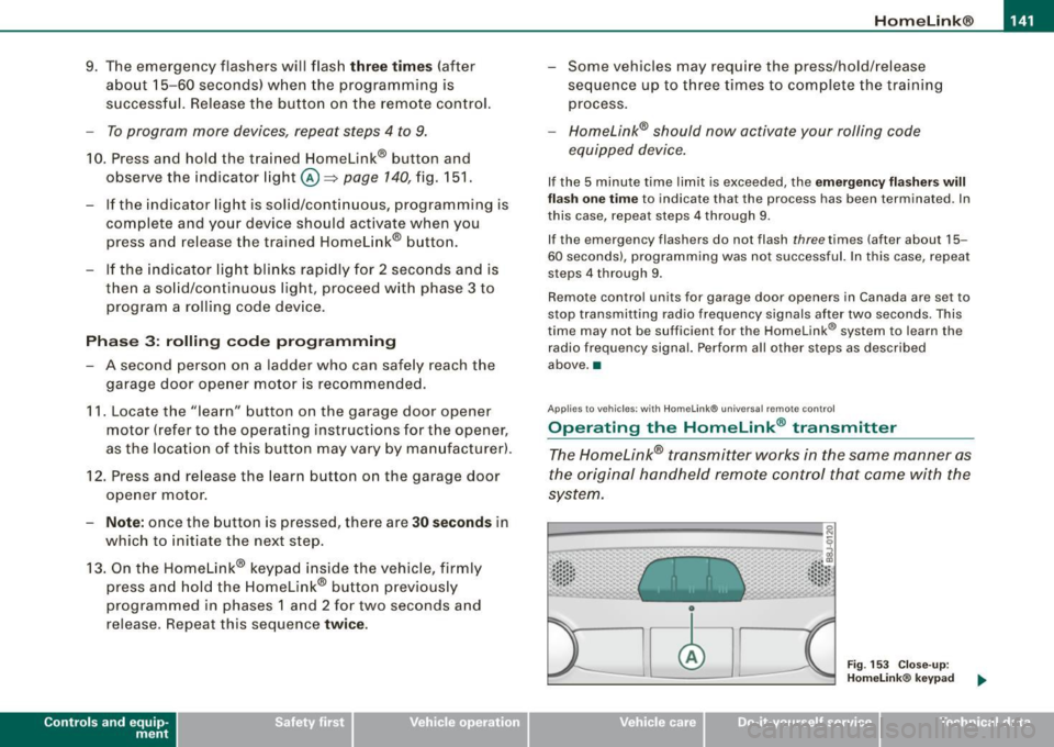
Operating the HomeLink ® transmitter
The Homelink® transmitter works in the same manner as
the original hand held remote control that came with the
system.
· ·· ·· ····· · ~::: ::; .• ... .. , '~· ·" ..
Fig . 153 Close-up:
Homelink® keypad
~ehicle care irechnical data
Page 233 of 340
Cleaning and protection -
----------------
•
High temperatures, as from exposure to intense sunlight, intensify
the corrosive effect particularly when humidity is high as well.
Under certain circumstances,
weekly washing may be necessary.
Under other conditions, a monthly washing and waxing may be
adequate.
After the winter, the
underside of the vehicle should be thoroughly
washed preferably in a professional car wash.
& WARNING
Always read and heed all WARNINGS and the information
~ page 230. •
Automatic car wash
The vehicle can be washed in almost any modern auto
matic car wash.
The vehicle paint is so durable that the vehicle can normally be
washed without problems in an automatic car wash. However, the
effect on the paint depends to a large extent on the design of the
facility, the filtering of the wash water, the type of wash and care
material , etc. If the paint has a dull appearance after going through
the car wash or is scratched, bring this to the attention of the oper
ator immediately . If necessary, use a different car wash .
The power top does not require specia l precautions before passing
through a car wash.
However, the car must not be treated with hot
wax after the wash cycle!
The wax could adversely affect the power
top and even damage the fabric over a period of time.
The power top does not have to be washed every time you use a car
wash . The power top can be spared if the car wash facility is
equipped with manually adjustable roof brushes or rollers.
Before going through a car wash, be sure to take the usual precau
tions such as closing the windows and power top. The factory-fitted antennas for the radio, car phone and navigation system* are all
located inside the vehicle interior.
If you have installed additional accessories on the vehicle
-such as
spoilers, etc. -it is best to ask the car wash operator if these should
be removed.
& WARNING
Always read and heed all WARNINGS and the information
~ page 230. •
Washing the vehicle by hand
A lot of water is needed when washing a vehicle by hand.
- Before you start washing, make sure you have read and
understood the WARNINGS=>
& in "General informa
tion" on page 230.
- First soak all dried dirt until it is soft, then rinse it off.
- As you clean your vehicle, start with the roof and work
your way down to the bottom, using a sponge, a sponge
glove or a clean brush.
- Rinse the sponge or the sponge glove often, flushing it
clean each time.
- Use special car shampoo only for very persistent dirt.
- Rinse the car thoroughly with water.
- Use a chamois leather to gently wipe the exterior dry.
Use a separate sponge for cleaning the wheels, door sills and other
regions exposed to road dirt. In this way, you wil l not scratch the
paint with coarse particles imbedded in the sponge the next time
you wash the car. ..,.
Vehic le care
Page 304 of 340
111!11.--___;;F...; u::. s.::..:: e~s :.....:: a..:..n .:..; d::....; b.:..:. u..:..lb ;:..:: s _______________________________________________ _
No.
38
39
41
42
43
Equipment
Central electric, anti -theft alarm system, rear
lid/trunk release
Radio
Horn
Vacant
Electronic Stabilization Program (ESP)
Engine timing
Seat heating
Automatic circuit breakers: Amps
15
20
25
25
15
35
The electric power windows and the electric seat adjusters are
protected with circuit breakers which reset automatically after the
circuit overload has been corrected .
[ i] Tips
• Whenever replacing a fuse, always consult the sticker on the
inside of the fuse panel cover. It contains the most up-to-date infor
mation regarding the fuse arrangement . If in doubt, ask your autho
rized Audi Service advisor.
• Some of the equipment items listed are optional or only avail
able on certain model configurations. •
Bulbs
Replacing light bulbs
For your safety, we recommend that you have your autho
rized Audi dealer replace burned out bulbs for you.
It is becoming increasingly more and more difficult to replace
vehicle light bulbs since in many cases, other parts of the car must first be removed before
you are able to get to the bulb. This applies
especially to the light bulbs in the front of your car which you can
only reach through the engine compartment.
Sheet metal and bulb holders can have sharp edges that can cause
serious cuts, and parts must be correctly taken apart and then prop
erly put back together to help prevent breakage of parts and long
term damage from water that can enter housings that have not
been properly resealed.
For your safety, we recommend that you have your authorized Audi
dealer replace any bulbs for you, since your dealer has the proper
tools, the correct bulbs and the expertise.
Gas discharge lamps (xenon lights)*:
Due to the high electrical voltage, have the bulbs replaced by a qual
ified technician. Headlights with xenon light can be identified by the
high voltage sticker.
& WARNING
Contact with high-voltage components of the electrical system
and improper replacement of gas discharge (Xenon) headlight
bulbs can cause serious personal injury and death.
• Xenon bulbs are pressurized and can explode when being
changed.
• Changing Xenon lamps requires the special training, instruc
tions and equipment.
• Only an authorized Audi dealer or other qualified workshop
should change the bulbs in gas discharge lamps.
& WARNING
There are parts with sharp edges on the openings and on the bulb holders that can cause serious cuts .
~
Page 307 of 340
______________________________________________ E_ m_ e_r -=g :...e _ n_ c __a. y_ s_it _u_ a_ ti_o _ n_ s _ __,11111
& WARNING (continued)
• Before you check anything in the engine compartment, always
read and heed all WARNINGS~ page 242, "Engine compartment".
0 Note
• Applying a higher voltage booster battery will cause expensive
damage to sensitive electronic components, such as control units,
relays, radio, etc .
• There must be no electrical contact between the vehicles as
otherwise current could already start to flow as soon as the positive
(+) terminals are connected.
[ i] Tips
The discharged battery must be properly connected to the vehicle's
electrical system. •
Use of jumper cables
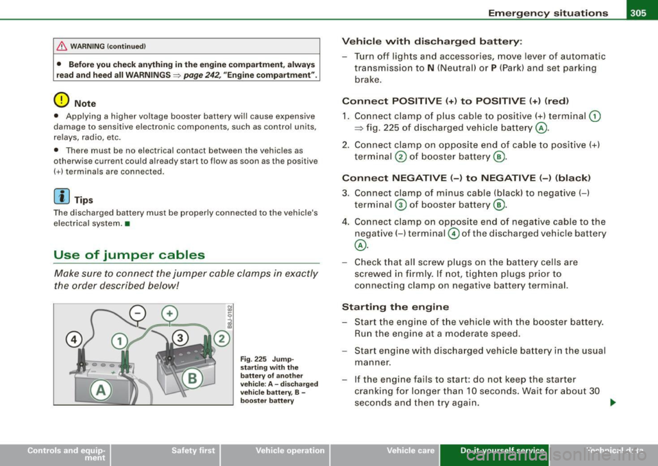
Make sure to connect the jumper cable clamps in exactly
the order described below!
Fig. 225 Jump·
starting with the
battery of another
vehicle : A -discharged
vehicle battery, B -
booster battery
Vehicle with discharged battery:
- Turn off lights and accessories, move lever of automatic
transmission to
N (Neutral) or P (Park) and set parking
brake.
Connect POSITIVE (+) to POSITIVE (+) (red)
1. Connect clamp of plus cable to positive(+) terminal G)
~ fig. 225 of discharged vehicle battery@.
2. Connect clamp on opposite end of cable to positive(+)
terminal
® of booster battery@.
Connect NEGATIVE (-) to NEGATIVE (-) (black)
3. Connect clamp of minus cable (black) to negative( -)
terminal
0 of booster battery@.
4. Connect clamp on opposite end of negative cable to the
negative( -) terminal © of the discharged vehicle battery
@.
- Check that all screw plugs on the battery cells are
screwed in firmly. If not, tighten plugs prior to
connecting clamp on negative battery terminal.
Starting the engine
- Start the engine of the vehicle with the booster battery.
Run the engine at a moderate speed.
- Start engine with discharged vehicle battery in the usual
manner.
- If the engine fails to start: do not keep the starter
cranking for longer than 10 seconds. Wait for about 30
seconds and then try again. .,,.
~ehicle care Do-it-yourse lf service Technical data
Page 321 of 340
_______________________________________________ C _o_ n _ s_u _ m_ e_ r_l_n _f_o _ r_ m_ a_ t _i _o _ n __ llll
& WA RNIN G (cont in u ed)
me nt zone s. Do ing so will in cre ase the r isk of injury if airb ags are
trig gered in an accident!
• Before you che ck anyt hing in the eng ine comp artment , al ways
re ad and heed all WARN IN GS =>
page 242.
0 Note
• If items other than genuine Audi spare parts, add-on equipment
and accessory items are used or if repair work is not performed
according to specified methods, this can resu lt in severe damage to
your vehicle 's engine and body (such as corrosion) and adverse ly
affect your vehicle's wa rra nty .
• If emergency repairs must be performed elsewhere, have the
vehic le examined by an authorized Audi dea lership as soon as
possible .
• The manufacturer cannot be held liable for damage which occurs
due to failure to comply with these stipulations. •
Installing/replacing a sound system
If you wish to install a radio or replace the factory installed radio,
p lease note the following:
The factory insta lled radio connectors are designed for genuine
Audi radios. When installing a different radio, difficu lties co uld arise
such as:
- the radio may not fit into the space provided
- the electrical connections may not be compatible
- different connector terminals may be needed .
Therefore, we recommend that you have your authorized Audi dea ler instal l or rep lace the radio.
Controls . and equip
ment . Safety first Vehicle operation They are the most fami
liar with the technical features of your
vehicle . They also offer Genuine Audi Radios wi th the necessary
insta llation components and instructions .
& WARNING
Improperly in sta ll ing a r adio co u ld cau se a short circu it and an
el ect rical fire. •
Technical Modifications
Our guidelines must be complied with when technical
modifications are made.
A lways consult an authorized Audi dealer before starting work on
any modifications .
This w ill help ensure that vehic le function, performance and safety
are not impaired=> &-
Attempting to work on electronic components and the software used with them can cause malfunctions. Because of the way elec
tronic components are interconnected with each other, such
malfunctions can also have an adverse affect on other systems that
are not directly involved . This means that you risk both a substantial
reduct ion in the operat ional safety of your vehicle and an increased
wear of vehicle parts=>&.
Authorized Audi deale rs wi ll perform this work in a professional and
competent manner or, in special cases, refer you to a professional
company that specializes in such modifications .
& WARNING
Improper repair s and modifica tion s ca n change the way vehi cle
sy stems work and cause serio us per sonal injur y.
IIJi,
Vehicle care Do-it-yourself service Tec hn ica l da ta
Page 322 of 340
___ C_ o_n_ s_ u_m _ e_ r_ ln_ f_ o _r _m _ a_ t_ i_o _n ______________________________________________ _
0 Note
If emergency repairs must be performed elsewhere, have the
vehic le examined by an authorized Audi dealership as soon as
possible .•
Declaration of Compliance,
Telecommunications and Electronic Systems
Rad io Frequency Devices an d Rad ioc ommunic ation
Equipment User Man ual N otic e.
T he manufacturer is not responsib le for any radio or TV interference
cause d by unauthorized mod ifications to this equipment .
Devic es
The fol lowing dev ices eac h comply with FCC Part 1 5.19, FCC Part
15.21 and RSS -Gen Issue 1:
• Cell phone package
• Electronic immobi lizer
• Homelink® unive rsal remote contr ol
• Remote control key
• T ire pressure monitoring system
FCC Part 15 .1 9
This device complies with part 15 of the FCC Rules. Operation is
subject to the fo llowing two cond itions:
(1) This device may not cause harmful interference, and
(2) this device must accept any interference received, inc luding
interference that may cause undesired ope ra tion .
FCC Part 15 .21
CAUT IO N: Changes or modifications not expressly approved by the party
responsible for complia
nce cou ld void the user's au thority to
operate the equipment.
RSS -Gen Is sue 1
Operation is subject to the following two conditions :
(1) th is device may not cause interference, and
(2) this device must accept any interference, including interference
that may cause undesired operation of the device. •