AUDI S4 SEDAN 2013 Owners Manual
Manufacturer: AUDI, Model Year: 2013, Model line: S4 SEDAN, Model: AUDI S4 SEDAN 2013Pages: 294, PDF Size: 73.71 MB
Page 251 of 294
When the malfunction indicator is illuminat
ed, the system may not be able to detect or
signal low tire pressure as intended. TPMS
malfunctions may occur for a variety of rea
sons, including the installation of replace
ment or alternate tires or whee ls on the veh i
cle that prevent the TPMS from funct io ni ng
p roperly . Always check the T PMS malfunct ion
tellta le afte r replacing one or more t ires or
wheels on your veh icle to ensure that the re
p lacement or a lternate tires and wheels allow
the TPMS to continue to function properly .
Tire pressure indicator appears
Applies to vehicles: with tire pressure monitoring system
The tire pressure indicator in the instrument
cluster informs you if the tire pressure is too
low or if there is a system malfunction.
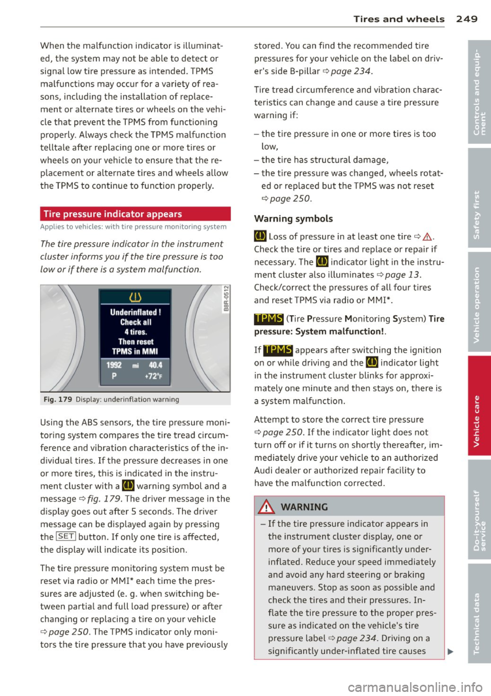
Fig. 179 Display : underinflatio n warning
Using the ABS sensors, the tire pressure moni
toring system compares the t ire tread circum
ference and vibration characteristics of the in
d iv idual tires . If the pressure decreases in one
or mo re tires, th is is indicated in the instru
ment clus ter with a
IE warning symbol and a
message ¢
fig. 179. The driver message in the
display goes out after 5 seconds. The driver message can be displayed again by pressing
the
! SET ! button. If only one tire is affected,
the display will indicate its pos ition.
The tire pressure monitoring system must be reset via radio or MMI* each time the pres
sures are adjusted (e.g . when switching be
tween partia l and full load pressure) or after
changing or replacing a t ire on your vehicle
¢
page 250. The TPMS indicator only moni
tors the tire pressure that you have prev iously
Tire s an d wheel s 249
stored . You can find the recommended t ire
pressures for yo ur vehicle on the label on driv
er's side B-pillar ¢
page 234.
Tire tread circum ference and vibration charac
teristics can change and cause a tire pressure
warning if:
- the t ire p ress ure in one or more tires is too
low,
- t he t ire has structural damage,
- the t ire pressure was changed, wheels rotat-
ed or replaced but the TPMS was not reset
¢ page 250.
Warning symbo ls
IE Loss of pressure in at least one tire¢.&,.
Check the tire or tires and replace or repa ir if
necessary. The
IE indicato r light in the inst ru
ment cluster a lso illuminates
c::!;> page 13.
Check/correct the press ures of all fou r tires
and reset TPMS via radio o r MMI*.
119;~, (T ir e Pressure Mon itoring System) Tire
pre ssure: Syst em malfun ction!.
If 11Nlf:1 appears afte r switching the ignition
on or while driving and the
IE indicator light
i n the instrument cluster blinks fo r approx i
mately one minute and then stays on, there is
a system malf unct ion.
Attempt to store the correct tire pressure
¢ page 250 . If the ind icator light does not
tu rn off o r if it turns on sho rtly the reafter, im
med iate ly dr ive your vehicle to a n author ized
Audi dealer or au thorized repair faci lity to
have the malfunc tion corrected .
A WARNING
-=
-If the tire pressure indicator appears in
the instrument cluster display, one or
more of your t ires is significant ly under
inflated. Reduce your speed immediately
and avoid any hard steer ing or braking
maneuvers. Stop as soon as possible and
check the tires and their pressures. In
flate the tire p ressure to the prope r pres
sure as indica ted on the vehicle's tire
pressu re labe l
¢page 234. Driving on a
significantly under-i nflated tire causes
•
•
Page 252 of 294
250 Tires and wheels
the tire to overheat and can lead to tire
failure. Under-inflation also is likely to
impair the vehicle's handling and stop
ping ability .
- The driver is responsible for maintaining
the correct tire pressures. You must
check the tire pressures regularly .
- Under certain conditions (such as a spor
ty driving style, winter conditions or un paved roads), the pressure monitor indi
cator may be delayed .
-Ask your authorized Audi dealer if run flat tires may be used on your vehicle.
Your vehicle registration becomes invalid
if you use these tires when not permit
ted. Damage to your vehicle or accidents
could also result.
@ Tips
- The tire pressure monitoring system
stops working when there is an ESC/ABS
malfunction.
- Using snow chains may result in a system
malfunction.
- The tire pressure monitoring system on
your Audi was developed using tires with the "AO" or "RO" identification on the
tire sidewall ¢
page 241. We recom
mend using these tires.
Reset tire pressure monitoring system
Applies to vehicles: with tire pressure monitoring system
If the tire pressure is adjusted, wheels are ro
tated or changed, the TPMS must be reset via
radio or MMI*.
11> Before resetting the TPMS, the current pres
sures of all four tires must correspond to
the specified values. Adjust the tire pressure and reset the pressure in the tire pressure
monitoring system according to the load
you are carrying
¢ page 234.
11> Turn on the ignition.
11> Select : the ICARI function button > Tire
pressure monitoring > Store now .
Or
i,. Select: the ICARI function button > Car sys·
terns
control button > Servicing & checks> Tire pressure monitoring
> Store tire pres
sures.
@ Tips
Do not store the tire pressure if there are
snow chains on the tire.
Page 253 of 294
What do I do now?
Vehicle tool kit
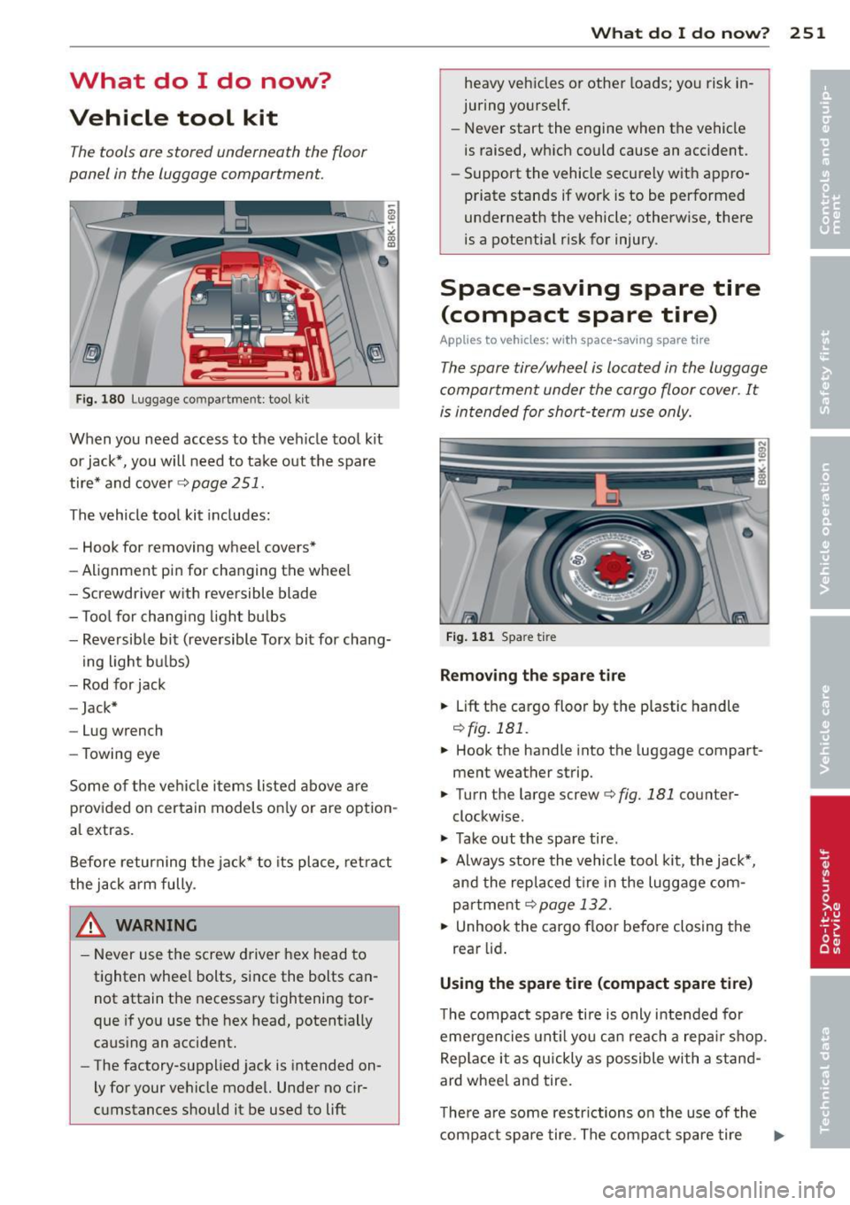
The tools ore stored underneath the floor
panel in the luggage comportment.
F ig . 180 Luggage compartment: tool kit
When you need access to the veh icle tool kit
or jack*, you will need to take o ut the spare
tire* and cover¢
page 251.
The vehicle tool kit includes:
- Hook for removing wheel covers*
- Alignment pin for changing the whee l
- Screwdriver w ith reversible blade
- T ool for chang ing light bulbs
- Reversible bit (reve rsible Torx bit for chang-
ing light b ulbs)
- Rod for jack
- Jack*
- Lug wrench
- Towing eye
Some o f the ve hicle items listed above are
p rov ided o n certain models on ly or are opt ion
a l extras.
Before returning the ja ck* to its place, ret ra ct
the jack a rm fully.
& WARNING
- Never use t he screw driver hex head to
tighten whee l bolts, since the bolts can
not attain the necessary tightening tor
que if yo u use the hex head, potentially
caus ing an accident.
- The factory-supplied jack is intended on
ly for your ve hicle model. Unde r no cir
c u mstances should it be used to
lift
What do I d o now ? 251
heavy ve hicles o r other loads; yo u risk in
juring yo urself.
- Never start the engi ne when the vehicle
is raised, which could cause an acc ident.
- Support the vehicle secu re ly wit h app ro
priate stands if wor k is to be performed
underneath the vehicle; otherwise, there
is a pote ntia l risk for injury.
Space-saving spare tire
(compact spare tire)
App lies to vehicles: wi th space -saving spare tir e
The spore tire/wheel is located in the luggage
comportment under the cargo floor cover. It
is in tended for shor t-term use only.
Fig. 181 Spare tire
Removing the spare ti re
.. Lift
th e ca rgo floo r by the p lastic handle
r:!) fig. 1 Bl.
.. Hook the handle into the luggage compart
ment weather strip.
.. Turn t he large screw ¢
fig. 181 counter
clockw ise.
.. Take out the spa re tire .
.. Always store the vehicle tool kit, the jack*,
an d the replaced tir e in the luggage com
par tme nt
¢page 132.
.. Unhook the cargo floor befo re closing the
rear lid .
Using the spare tire (compact spare tire)
The compact spa re ti re is only intended for
eme rgencies unt il yo u ca n reac h a repa ir sh op.
Rep lace i t as quickly as possible with a stan d
ard whee l and tire.
T he re a re some restr ictions o n the use of the
compact sp are tire. The compa ct spare tire
IJ>
Page 254 of 294
252 What do I do now?
has been designed specifically fo r you r type of
vehicle . It must not be swapped with a com
pact spare t ire from another type of veh icle.
Snow cha ins
F or technical rea son s, the use of snow chains
on the compact spare tire is
not p ermitt ed .
If you do have to dr ive with snow cha ins and a
front tire fails, mount the spare whee l w ith
tire instead of a rear t ire. Install the snow
cha ins on the rear tire and use it to rep lace
the defective front tire .
A WARNING
-Never use the spare tire if it is damaged
or if it is worn down to the tread wear in
dicators.
- If the spare tire is more than 6 years o ld,
use it only in an emergency and w ith ex
treme caution and careful driving.
- The spare tire is intended only for tem
porary and short-term use. It should be
replaced as soon as possib le w ith the
normal wheel and tire.
- After mounting the compact spare tire,
the tire pressure must be checked as
soon as poss ible. The tire pressure of the
compact spa re tire must be 4.2 bar; oth
erw ise, you risk hav ing an accident.
- Do not drive faster than SO mph (80 km/
h). You risk having an acc id ent.
-Avoid full-throttle acce le rat ion, heavy
braking, and fast corner ing . You risk hav
ing an acc ident.
- Never drive us ing more than one spare
wheel and tire. You risk having an acci
dent .
- Normal summer or winte r tires must not
be mounted on the compact spare whee l
rim.
- For technical reasons, the use of ti re
c hains on the spare tire is not permitted.
If it is necessa ry to dr ive wi th tire ch ains,
the spare whee l must be mounted on the
front axle in the event o f a f lat in a rear
t ir e. The newly ava ilable front wheel
must then be installed in place of the rear whee
l with the flat tire. Installing
the t ire cha in before mounting the whee l
and tire is recommended.
- Loose items in the passenger compart
ment can cause serious personal injury
during hard brak ing or in an accident.
Never store the inflatable spare tire or
jack and tools in the passenge r compart
ment.
Changing a wheel
Before changing a wheel
Observe the following precautions for your
own and your passenger's safety when chang
ing a wheel .
.,. After you experience a t ire failure, p ull the
car we ll away from moving traffic and try to
reach
level ground before you stop ¢ A .
.,. All passengers should lea ve the car and
move to a safe location (for instance, behind
the guardrail)¢
A.
.,. Engage the park ing brake to prevent your
ve hicle from rolling unintentionally ¢
A.
.,. Shift into 1st ge ar on veh icles with manual
transmiss ion, or move th e
selector lever to
the P positi on
on vehicles w it h automatic
transmiss io n.
.,. If you are towing a trai ler : u nhitch the trail
er from your vehicle .
.,. Take the
jack ¢ page 251 and the spare tire
¢ page 251 out of the luggage compart
ment.
A WARNING
You or your passengers could be injured
while changi ng a wheel if you do not fo l-
l ow these safety precaut ions:
- If you have a flat tire, move a safe d is
tance off the road. Turn off the engine,
tur n the eme rgency flashers on and use
o ther warni ng device s to a le rt othe r mo
torists.
- Make sure that passengers wait in a safe
place aw ay from the vehicle a nd well
-
away from the road and traffic . ~
Page 255 of 294
-To he lp prevent the vehicle from moving
sudden ly and possibly slipping off the
jack, always fully set the parking brake and block the whee l diagona lly opposite
the wheel being cha nged with the fold
ing chocks o r othe r objects. When one
front whee l is lifted off the g ro und, plac
ing the A utomat ic Transm iss ion in "P"
(Park) wi ll
not prevent the vehi cle from
moving .
- Before you change a wheel, be su re the
ground is level and f irm . If necessa ry,
use a sturdy board under the jack.
- After installing the spare tire, make s ure
that you replace the flat ti re/wheel in its
storage area proper ly and tighten the
knur led retain ing screw securely .
Q;) Note
If you are changing the wheel on a steep
incline, use a rock or similar object to
block the opposite wheel to prevent the
veh icle from mov ing.
Obey all laws .
Changing a wheel
When you change a wheel, follow the se
quence described below step -by-step and in
exactly that order.
1. Remove the d ec orative wheel c ove r* or
the
wheel bolt cap s*. Fo r more de tails see
a lso
¢ page 2 54, Decorative wheel cov
ers
or ¢ page 2 54, Wheels with wheel
bolt caps.
2 . Loosen the wheel bolts ¢ page 254.
3. Locate the proper mount ing po int for the
jack and align the jack below that point
¢ page 255.
4. Lift the car with the jack ¢ page 2 55.
S. Remove the wh eel with th e flat tire and
then install the
s pare tire¢ page 256.
6. Tighten all wheel bo lts light ly .
7.
Lower the vehicle with the jac k.
What do I do now? 253
8. U se the wheel bolt w rench and firmly
tighten a ll wheel bolts in a crisscross pat
te rn ¢
page 254.
9. Replace the decorati ve wheel co ver* or
the
wheel bolt caps* .
A WARNING
Always read and fo llow all WARNINGS and
info rmat ion¢
A in Raising the vehicle on
page 255
and ¢ page 257.
After changing a wheel
A wheel change is not complete without the
doing the following.
.,. Always store the vehicle tool kit, the jack*,
and the replaced tire in the luggage com
partme nt
¢ page 132.
.,. Check the tire pr essure of the spare ti re as
soon as possible.
.,. As soon as possib le, have the
ti ght ening
torque s
on all wheel bolts chec ked w ith a
torque wrench . The correct tightening tor
que
i s 90 ft l bs. (120 Nm) .
.,. Have the flat tire replaced as soon as possi
ble .
(D Tips
-If you notice that the wheel bo lts a re
corroded and difficult to turn while
chang ing a tire, they should be replaced
before you check the tightening torque.
- Dr ive at reduced speed until you have the
tightening torques checked. •
•
Page 256 of 294
2 54 What do I do now ?
Decorative wheel covers
Applies to vehicles: with decorative wheel covers
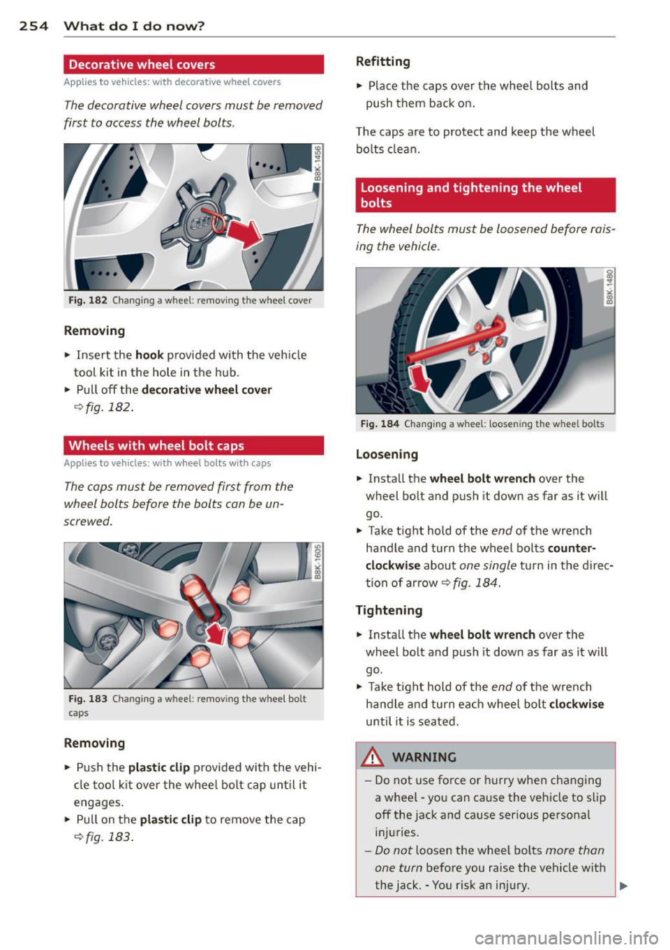
The decorative wheel covers must be removed
first to access the wheel bolts .
Fig. 182 Changing a w hee l: remov ing the w heel cover
Removing
.. Insert the hook provided with the vehicle
tool kit in the hole in the hub .
.. Pull off the
decorative wheel cover
~fig. 182 .
Wheels with wheel bolt caps
Applies to vehicles: with wheel bolts w ith caps
The caps must be removed first from the
wheel bolts before the bolts con be un
screwed .
Fig. 183 Chan gin g a w hee l: rem ov ing the w heel bo lt
c ap s
Removing
.. Push the plastic clip provided with the vehi
cl e too l kit over the wheel bolt cap until it
engages.
.. Pull on the
plastic clip to remove the cap
9fig. 183 .
Refitting
.. Place the caps over the whee l bolts and
push them back on .
T he caps are to protect and keep the wheel
bolts clean.
Loosening and tightening the wheel
bolts
The wheel bolts must be loosened before rais
ing the vehicle.
Fig. 184 Changing a wheel: loosening the whee l bo lts
Loosening
.. Install the wheel bolt wrench over the
wheel bolt and push it down as far as it w ill
go.
.. Take tight hold of the
end of the wrench
handle and turn the wheel bolts
counter
clockwise
about one single turn in the direc
tion of arrow
9 fig. 184.
Tightening
.. Install the wheel bolt wrench over the
wheel bolt and push it dow n as far as it will
go .
.. Take tight hold of the
end of the wrench
handle and turn ea ch wheel bolt
clockwise
until it is seated.
,&_ WARNING
-= -
- Do not use force or hurry when changing
a wheel -you can cause the vehicle to slip
off the jack and cause serious personal injuries.
- Do not loosen the wheel bolts more than
one turn
before you raise the vehicle with
the jack. -You risk an injury. ..,.
Page 257 of 294
@ Tips
-Never use the hexagonal socket in the
handle of the screwdriver to loosen or
tighten the wheel bolts.
- If a whee l bolt is very tight, you may find
it easier to loosen by carefully pushing
down on the end of the wheel bolt
wrench w ith
one foot only. As you do so,
hold on to the car to keep your ba lance
and take ca re not to slip.
Raising the vehicle
The vehicle must be li~ed with the jack first
before the wheel can be removed .
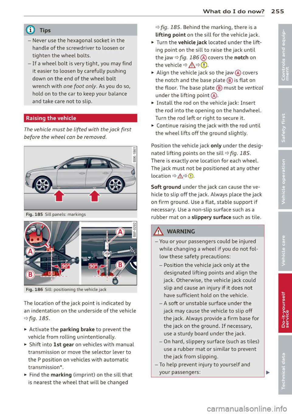
Fig. 1 85 Sill pane ls: ma rki ngs
Fi g. 186 Sill: posit ion ing the ve hicle jack
The location of the jack point is indica ted by
a n in den ta ti on on the underside of the vehicle
Q fig . 185.
"' Activate the parking brake to prevent the
vehicle from ro lling u ninten tionally.
"' Sh ift into
1 st gear on vehicles with m anua l
transmission or move the se lector lever to
the P position on vehicles with automatic
transmission* .
"' Find the
mark ing (imprint) on the sill that
is nearest the wheel that will be changed
What do I d o now ? 255
¢ fig. 185. Behind the marking, there is a
lifting point on the sill for the vehicle jack.
"' Turn the
vehicle jack located under the lift
ing point on the sill to ra ise the jack until
the jaw ¢
fig. 186 @ covers the notch on
the vehicle
¢ & ¢ (D .
"' Align the vehicle jack so the jaw@ covers
th e notch and the base plate @ is flat on
the floor. The base plate @ must be
vertical
unde r th e lift ing po in t @ .
"' Insta ll the rod on the vehi cle jack: Insert
the rod into the opening on the handwheel.
Turn the rod left or right to secure it.
"' Cont inue raising the jack w ith the rod unt il
the wheel lifts off the ground slightly.
Position the veh icle jack
only under the desig
nated lifting points on the sill ¢
fig. 185 .
There is exactly one location for each wheel.
The jack must not be positioned at any other location
¢ ,&. ¢(I) .
Soft ground under the jack can cause the ve
hicle to slip off the jack. Always place the jack
on f irm ground. Use a f lat, stab le support if
necessary . Use a non-slip surface such as a
rubber mat on a
s lipp ery surface such as tile .
A WARNING
-You or your passengers co uld be in ju red
while c hanging a whee l if you do no t fo l
low these safety p re ca utions:
- Position t he veh icle jack on ly at the
designated lifting poi nts and align the
jack. Otherw ise, the vehicle jack could
slip a nd cause an injury if it does not
have sufficie nt hold o n the vehicle.
- A soft or unstable surface under the
jac k may cause the ve hicle to slip off
the jack . A lways prov ide a fi rm base for
the jack o n the ground. If necessa ry,
u se a st ur dy boa rd under the jack .
- On hard, sl ippery su rface (such as t iles)
u se a rubber mat or simi lar to prevent
the j ack from slipping.
- T o help preve nt injury to yo urself and
your pas sengers:
Page 258 of 294
256 What do I do now?
-Do not raise the vehicle unti l yo u are
sure the jack is securely engaged.
- Passengers must not remain in the ve
h icle when it is jacked up.
- Make sure that passengers wait in a
safe p lace away from the vehicle and
well away from the road and traffic.
- Make sure jack position is correct, ad
just as necessary and then continue to ra ise the jack.
CD Note
Do not lift the vehicle by the sill. Position
the vehicle jack only at the designated lift
ing points on the sill. Otherwise, your vehi
cle will be damaged.
Taking the wheel off/installing the spare
tire
Follow these instructions step-by-step for
changing the wheel .
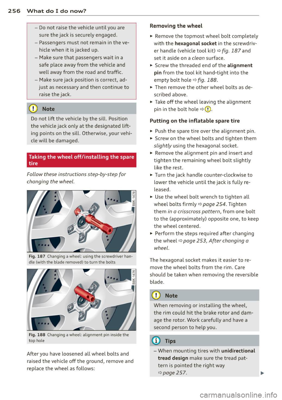
Fig. 187 Changing a w hee l: usi ng the screwdriver han ·
dle (with the blade r~mo ved) to turn th e bo lts
Fig. 188 C hangin g a w hee l: alig nmen t pin inside the
to p hole
After you have loosened a ll wheel bolts and
ra ised the veh icle off the ground, remove and
replace the wheel as follows:
Removing the wheel
.,. Remove the topmost whee l bolt completely
with the
hexagonal socket in the screwdriv
er handle (vehicle tool kit)¢
fig. 187 and
set it aside on a
clean surface .
.,. Screw the threaded end of the
alignment
pin
from the tool kit hand-t ight into the
empty bolt hole ¢
fig. 188.
.,. Then remove the other wheel bolts as de
scribed above.
.,. Ta ke off the wheel leaving the alignment
pin in the bolt hole
c::>(D .
Putting on the inflatable spare tire
.,. Push the spare tire over the alignment p in.
.,. Screw on the wheel bolts and tighten them
slightly using the hexagonal socket .
.,. Remove the alignment pin and insert and
tighten the remain ing wheel bolt slightly
like the rest.
.,. Turn the jack hand le counter -clockwise to
lower the veh icle until the jack is fully re
leased .
.,. Use the wheel bolt wrench to tighten all
wheel bolts firmly
c::> page 254 . Tighten
them
in a crisscross pattern, from one bolt
to the (approximately) opposite one, to keep
the wheel centered .
.,. Perform the steps required after changing
the wheel
c::> page 253, After changing a
wheel.
T he hexagonal socket ma kes it easier to re
move the wheel bolts from the rim. Care
should be tak en when removing the reversible
blade .
CD Note
When removing or installing the wheel,
the rim could hit the brake rotor and dam
age the rotor. Work carefu lly and have a
second person to help you.
(D Tips
-When mounting tires with unidirectional
tread design
make sure the tread pat
tern is pointed the right way
c::>page257. ..,.
Page 259 of 294
-The wheel bol ts should be clean and easy
to tu rn. Check for d irt and corrosion on
t h e mat ing s urfaces of both the whee l
and t he hu b. Remove a ll dirt from these
su rfaces before remo unt ing t he wheel.
- Do n ot use the hexagonal socket in the
screwdriver ha ndle to loosen or tig hten
t h e wheel bo lts .
Tires with unidirectional tread design
Tires with unidirectional tread design must be
mounted with their tread pattern pointed in the right direction.
Using a spare tire with a tread pattern
intended for use in a specific direction
When using a spare tire w ith a t read patte rn
i ntended for use in a specific direction, please
n ot e th e follow ing:
- The direction of rotation is ma rked by an
ar
row on the s ide of the t ire .
-If the spare t i re has to be installed in the in
correct di rection, use the spare tire only
temporar ily since the t ire will not be able to
achieve its optimum perfo rma nce character
ist ics with r ega rd to aquaplani ng, noise and
wea r.
- We recommend that you pay particular at
tent io n t o this fact du ring wet weathe r and
t h at you adjus t your spee d to matc h road
cond itio ns.
- Replace th e flat tire w ith a n ew one and
have it ins talled o n your ve hicle as soon as
poss ible to re st ore the hand ling advant ages
of a uni direct io na l t ire .
Notes on wheel changing
Please rea d the information ¢ page 241, New
tires and replacing tires and wheels
if you are
going to use a spare t ire which is different
from the tires on your ve hicle.
Afte r you change a tire :
-Check the tire pressure on the spare imme
diately after installation . What do I do now? 257
- Have the wheel bolt tightening torque
checked with a torque wrench as soon a s
possible by your authorized Audi dealer or
a qualified workshop .
- With steel and alloy wheel rims , the wheel
bolts are cor rectly tightened at a torque of
90 ft lbs. (120 Nm ).
- If you notice that the wheel bolts are cor·
roded and difficult to turn while changing
a tire, they should be replaced before you
check the tightening torque .
- Replace the flat tire with a new one and
have it installed on your veh icle as soon as
possible. Remount the wheel cover.
Until then , drive with extra care and at re·
duced speeds.
A WARNING
-
- If you are going to equ ip your ve hicle
w it h tires o r rims which differ from those
which w ere fac to ry installed, t hen be
s ure to re ad the information ¢
page 241 ,
N ew tire s and re pla cing tires and
whee ls.
- Always make s ure th e da maged wheel o r
eve n a flat t ire and t he j ack and to ol ki t
a re p roperly secu red in the lugg age com
pa rtment an d are no t loose in the pas
sen ger compartment.
- In an accident or sud den maneuver they
co uld f ly forwa rd, in ju ring a nyo ne in the
ve hicle .
-A lways s to re damage d wheel, jack and
too ls sec urely in the luggage compa rt
ment . Othe rwise, in a n accident o r su d
den maneuver they co uld f ly forwa rd,
causing inju ry to passengers in the ve hi·
cle.
~ Note
Do not use comme rcially ava ilab le tire
sea lants. Ot herwise, t he e lectr ica l comp o
n ents of t he tire pressu re monitoring sys
t em * w ill no longe r work pr operly and the
senso r fo r th e tire pressure moni tor ing
syst em* will have to be replac ed by a
qu alified wor kshop . •
•
Page 260 of 294
258 Fuses a nd bulb s
Fuses and bulbs
Fuses
Replacing a fuse
Fuses that have blown will have metal strips
that have burned through.
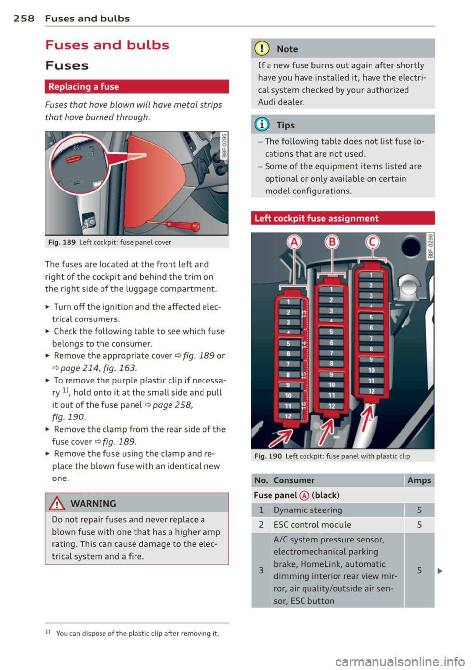
Fig. 189 Left cockpit: fuse panel cover
The fuses are located at the front left and
right of the cockpit and behi nd the trim on
the right side of the luggage compartment.
• Turn off the ignit ion and the affected elec
trical consumers.
• Check the following table to see which fuse
belongs to the consumer.
• Remove the appropriate cover ¢
fig. 189 or
¢page 214, fig.163.
• To remove the purple plastic cl ip if necessa
ry
1l, hold onto it at the small side and pull
it out of the fuse panel
c:> page 258,
fig. 190 .
• Remove the clamp from the rear side of the
fuse cover ¢
fig. 189.
• Remove the fuse using the clamp and re
pla ce the blown fuse w ith an ident ical new
one.
A WARNING
Do not repair fuses and never replace a
blown fuse with one that has a higher amp
rating. This can cause damage to the elec
trical system and a fire.
ll You can dis pose of the plastic clip after removing it.
(D Note
If a new fuse burns out again after shortly
have you have installed it, have the electri
cal system checked by your authorized
Audi dealer.
(D Tips
- The following table does not list fuse lo
cations that are not used.
- Some of the equipment items listed are
optional or only available on certain
model configurations.
Left cockpit fuse assignment
Fig. 190 Left cockpit: fuse panel with plastic clip
No. Consum er
Fu se pan el@ (bl ack)
1 Dynamic steering
2 ESC control module
3
A/C system pressure sensor,
electromechanical parking brake, Homelink, automatic
dimming interior rear view mir ror, air quality/outside air sen
sor, ESC button
Amp s
5
5
5